EP0138561A2 - Dachraumbelüftung - Google Patents
Dachraumbelüftung Download PDFInfo
- Publication number
- EP0138561A2 EP0138561A2 EP84306884A EP84306884A EP0138561A2 EP 0138561 A2 EP0138561 A2 EP 0138561A2 EP 84306884 A EP84306884 A EP 84306884A EP 84306884 A EP84306884 A EP 84306884A EP 0138561 A2 EP0138561 A2 EP 0138561A2
- Authority
- EP
- European Patent Office
- Prior art keywords
- tiling
- wall portion
- ventilation
- tiling member
- baffle
- Prior art date
- Legal status (The legal status is an assumption and is not a legal conclusion. Google has not performed a legal analysis and makes no representation as to the accuracy of the status listed.)
- Granted
Links
Images




Classifications
-
- E—FIXED CONSTRUCTIONS
- E04—BUILDING
- E04D—ROOF COVERINGS; SKY-LIGHTS; GUTTERS; ROOF-WORKING TOOLS
- E04D13/00—Special arrangements or devices in connection with roof coverings; Protection against birds; Roof drainage ; Sky-lights
- E04D13/17—Ventilation of roof coverings not otherwise provided for
- E04D13/174—Ventilation of roof coverings not otherwise provided for on the ridge of the roof
Definitions
- This invention relates to the ventilation of pitched roof spaces and more particularly to high-level roof ventilation.
- Roof ventilation is essential in pitched roof spaces in order to control condensation which, if permitted to occur, can result in mould growth, rot and distortion of roof timbers, metal corrosion, ceiling damage and reduced thermal insulation.
- eaves to ridge ventilation which involves a flow of air into the roof space from the low level of the eaves to the high level of the ridge.
- the object of eaves to ridge ventilation is to achieve adequate ventilation whatever the wind direction, convectional ventilation in windless conditions, satisfactory mixing of air throughout the roof space and uniform outflow of air from the roof space.
- the present invention consists in a tiling member for use in the ventilation of a pitched roof space at high level, said member being adapted to rest on and extend transversely of the upper surface of a roofing tile, and having an upper portion for supporting at least a portion of a longitudinal side edge of a ridge tile, an elongate ventilation area comprising a plurality of ventilation apertures extending transversely of the roofing tile when the tiling member is rested thereon, a baffle depending from the upper portion behind the ventilation apertures and a ventilation opening behind the baffle, whereby, when the tiling member forms part of a tiled pitched roof structure, roof a flow of air from a/space can pass into the tiling member through the ventilation opening, around the baffle and out through the ventilation apertures.
- a substantially continuous area of ventilation along the length of a roof ridge is achieved, ensuring sufficient volume of air flow through and out of the roof space whatever the wind direction and in windless conditions, the apertures of the elongate ventilation area can be made of such a size as to prevent the entry of large insects into the roof space yet ensure adequate air flow and the baffle reduces any wind pressure.
- the tiling member constructed according to the present invention can be made in one-piece e.g. a one-piece plastics moulding, and is simple to fit in that it can accommodate variations in the laying of the tiles.
- the ventilation area preferably has the configuration of a grille, with the apertures being elongate in form and extending transversely of the direction of the grille.
- the ventilation area forms part of a front wall portion which depends from a front region of the upper portion and is spaced from the baffle, the front portion having a lower edge which has the general shape of the nib of the particular roofing tile with which the tiling member is to be used in the case of contoured roofing tiles or is flat or straight in the case of plain tiles.
- a rear wall portion depending from the upper portion behind the baffle and preferably extending downwardly for a greater distance than the front wall portion so as to engage against the top edge of a roofing tile of the uppermost tile course to hold the tiling member thereon.
- the rear wall portion could be extended still further to permit the tiling member to be nailed to the top tiling batten through the further extension to prevent it being blown inwards by strong winds and/or stop a flow of air into the tiling member from between the roof felt and roofing tiles.
- the lower edge of the rear wall portion has a shape which is generally the same as the lower edge of the front wall portion.
- the upper, front and rear wall portions define an open-bottomed chamber in the tiling member whose open-bottom is closed by the upper surface of a roofing tile when the tiling member is positioned thereon.
- the chamber is divided into front and rear portions by the baffle which extends downwardly for a lesser distance than the front portion to permit a flow of air around the baffle and out of the ventilation apertures.
- the ventilation opening opens into the chamber rear portion from the upper portion and has a hood or cowl to prevent the membrane closing the ventilation opening.
- the ventilation opening could be in the rear wall portion behind the baffle.
- the upper portion may have a plurality of spaced apart stops or projections extending along its front edge to guard against the possibility of the tiling member being blown inwards by strong winds.
- the tiling member has support elements extending transversely thereof and in the direction of a roofing tile when laid thereon and which engage with, and further support, the tiling member on the upper surface of a roofing tile and ensure that the tiling members adequately support the ridge tiles, particularly in the case of contoured roofing tiles having shallow pans and with plain tiles.
- the apertured ventilation area preferably lies substantially in the pan when the tiling member is laid thereon but, in the case of shallow panned contoured roofing tiles and plain roofing tiles the ventilation area preferably lies above the pan and the top surface of the roofing tile.
- the present invention consists in a pitched roof structure comprising a plurality of roofing tiles laid in courses on roof battens, and a plurality of any of the tiling members as defined hereinabove resting on roofing tiles of the or each uppermost course with the apertured ventilation area facing outwards.
- the roof structure includes a plurality of ridge tiles arranged in end to end relationship along the roof ridge with the longitudinal side edges of the ridge tiles resting on the upper portions of the tiling members on opposite sides of the roof apex with dual pitch roofs, and with mono-pitch roofs the ridge tiles are half- ridge tiles and one of their longitudinal side edges rests on the upper portions of the tiling members.
- ridge tiles are not used and the tiling members will be at the top of the roof and can easily be held in position by a clip and/or flashing and/or by nailing the further extension of the rear wall portion, if provided.
- a tiling member which is generally indicated at 1 may be made of any suitable material such as plastics, metal or a cementitious material but is preferably a one-piece plastics moulding, conveniently of polyethylene or polyvinyl chloride, and comprises an upper wall portion 2 forming a platform. Depending generally perpendicularly from the platform 2 are parallely extending front and rear wall portions 3 and 4 which, with the platform define an open-bottomed chamber 5.
- the front portion is formed with an elongate apertured ventilation area 6 which can extend up to the entire length of the front wall portion 3 and comprising a plurality of vertically arranged transversely extending ventilation apertures 7 to form a ventilation grill.
- the chamber 5 is divided into front and rear portions 5a and 5b respectively by a baffle 8 depending from the platform 2 and extending parallel to the wall portions 3 and 4 behind the apertured ventilation area 6.
- This embodiment is for use with contoured roofing tiles of double channelled configuration with shallow pans.
- the bottom edge 9 of the front wall portion 3 is contoured to match generally the shape of the tile nib (not shown) to that the tiling member can fit loosely into the tile pan areas and thus accommodate variations in the laying of the roofing tiles.
- the bottom edge of the rear wall portion 4 is also contoured to be of similar shape and projects downwardly for a greater distance than the front wall portion 3 to provide a holding portion 10 which engages with the upper edge of the roofing tile when laid thereon and prevents the tiling member from slipping down the roof.
- the front and rear wall portions 3 and 4 are joined by transversely extending support members in the form of strips 11 having straight bottom edges which engage with the top surface of the contoured roofing tile to ensure that the tiling member takes the weight of the ridge tiles.
- the transversely extending support members could be in the form of rows of projections or pegs.
- the support members 11 are of particular importance with plan or flat tiles for preventing collapse of the tiling member.
- the opening 12 is provided with a cowl or hood 13 for a purpose to be described.
- a row of ridge tile stops 14 constituted by projections or pegs project upwardly from the platform 2 along its front edge for guarding against the possibility of the tiling member being blown inwards for a sufficient distance to prevent it being weatherproof.
- the ridge portion of a tiled dual pitch roof structure comprises spaced apart pairs of wooden rafters 15 to which are secured roof battens 16 with roofing felt 16a laid therebetween.
- Figures 4 and 5 show the upper courses of concrete roof tiles 17 laid on the battens 16 with the nibs at their upper edges fitted over the battens.
- At the apex of the rafters 15 are secured, at spaced apart intervals, supporting brackets such as 18 for a ridge batten 19 to which the ridge tiles such as 20 are nailed by nails (not shown).
- the opposed ends of the ridge tiles 20 may be joined by concrete, or, preferably, (not shown) opposed ends of the ridge tiles are secured together by fixing or jointing members such as are described in the specification of our co-pending British Patent Application No. 8414440 to form a "dry" ridge system.
- the roofing tiles 17 are of double-channelled configuration with shallow pans and interlock along their side edges.
- the tiling members 1 are laid in position on the upper surfaces of the upper portions of the roofing tiles 17, one for each roofing tile, with the contoured lower edges of the front portions 3 engaging with the pan and top surfaces of the roofing tiles with their holding portions 10 engaging with the upper edges of the top courses of the roofing tiles to hold the tiling members in position.
- the ridge tiles 20 are then laid over the ridge so that their longitudinal side edges engage with the platform portions 2 of the tiling members 1 on opposite sides respectively of the ridge between the hoods 13 and the ridge tile stops 14.
- the support members 11 rest on the flat top surface of the roofing tiles 17.
- the fixing members can be fitted onto the adjacent ridge tile ends and the ridge tiles 20 are nailed onto the ridge batten 19.
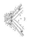
- the tiling members 1 provide for high-level ventilation of the roof space 21 such that there is a flow of air as indicated by the dashed line 22 in the direction of the indicated arrows out through the gaps between apex of the rafters 15 and upper edges of the roofing tiles 17, through the entry openings 12 of the chamber 5 around the baffle 8 and out through the apertured ventilation area 6.
- the wind pressure on the right hand side of the tiled structure as illustrated in Figure 5 will produce a low pressure area on the left hand side of the roof which induces a flow of air out through the tiling members 1 on the left hand side of the roof structure as indicated by the dashed line 22.
- Wind tests have been carried out by the Applicants with simulated wind speeds of up to 60 mph (96.54 kmh) and it has been found that when air flows through the ventilation apertures 7 in the direction indicated by the arrowed dashed line 23 (see Fig. 2), the baffle 8 acts to reduce the pressure due to wind in the rear chamber portion 5b as evidenced by pressure readings taken therein. Moreover, when water was entrained in the air flow in such tests, the baffle 8 prevented the entry of such wind driven water, not only into the chamber portion 5b but also into the roof space 21.
- the hood 13 serves to prevent closing of the opening 12 in the event of using a secondary water check, as indicated by the dashed lines 23a in Figure 5.
- This water check 23a consists of a waterproof membrane and passes over the ridge batten 19 and underneath the longitudinal side edges of the ridge tiles 20 where they rest between the tile stops 14 and the hood 13.
- the hood 13 also serves to deflect the air flow from the roof space into the tiling member.
- Figs. 6 to 8 differs from that of Figs. 1 to 3 in that the tiling member la is specially adapted for a deep pan bold roll contoured roofing tile and has front and rear wall portions 3 and 4 of greater depth (compare Figs. 2 and 7) to accommodate the deeper pan with the apertured ventilation area 6 being disposed in the pan between the roofing tile rolls when positioned thereon, whereas in Figs. 1 to 3 the ventilation area 6 is disposed above the pans and top surface of the roofing tiles as will be apparent from Fig. 4.
- the requisite volume of air flow from the roof space is provided by increasing the length of ventilation apertures 7.
- two support members 11 only are provided which rest against the tile pan and which are cut away as indicated at lla to provide a facility for accommodating a transverse raised barrier on the upper end portion of a roofing tile.
- the support members 11 in this embodiment could, however, be dispensed with.
- a substantial part of the upper wall portion 2a is of arcuate, outwardly curved, configuration as viewed in cross-section and extends upwardly and rearwardly at an angle of greater than 90° from the front wall portion 3(unlike the upper wall portion 2 which is at an angle of about 90° to the front wall portion 3) and stops short of the rear wall portion 4 so that the ventilation opening is defined between the rear edge of the upper wall portion 2a and front edge of the remaining flat portion 2b of the upper wall portion which extends at an angle of about 90° to the rear wall portion 4.
- the upper portion 2a is flat.
- Such modifications are particularly suitable for tapered ridge tiles.
- the upper wall portion 2a also serves the function of the cowl or hood 13.
- an additional baffle 8a depends from the upper wall portion 2a for facilitating the flow of air into the tiling member and for preventing blow through from the exterior.
- tiling members constructed in accordance with the invention also provide for a flow of ventilating air from between the roofing felt 16a and the roofing tiles 17 and into the tiling members 1, (la) as shown in arrowed dashed lines 30.
- the rear wall portion may be extended still further so that its bottom edge engages with the roofing felt 16a to stop this flow of air.
- the further extension of the rear wall portion also or instead permits nailing of the tiling member to the top tiling batten 16.
- the tiling members such as previously described instead of being in one piece may be made in two or more elongate elements which are positioned in correct relationship to one another in situ on the roof or are fitted together either in situ or before laying e.g. by means of interengaging members such as projections and apertures or recesses, to form the complete tiling member.
- the elongate elements may extend over one or preferably several roofing tiles, and be as long, for example, as 3 metres.
- these elements could comprise the upper portion, the rear wall portion and the front wall portion.
- the elongate apertured ventilation area could be continuous.
- tiling member is used herein in a generic sense to cover a ventilation member which can be used with all types of pitched roof coverings which need not necessarily be ridge and roofing tiles.
- the ridge covering could be say a plastics elongate ridge covering extending over several normal tile widths and the roof covering instead of being of roofing tiles could be of shingles, slates or of panels e.g. of a suitable metal such as aluminium which may be coated, or of asbestos,and which may be flat, corrugated, or contoured to give an appearance of contoured roofing tiles.
- Such panels may be 3 x 6 metres, for example.
- "ridge tiles” and “roofing tiles” are used herein in a generic sense to cover all kinds of ridge and roof coverings used for pitched roofs.
- the elongate ventilation apertured area can extend for any suitable distance up to the full width of a roofing tile.
- the ventilation apertures may be in the form of elongated narrow slots or slits arranged one above the other and extending lengthwise of the ventilation area 6.
- the tiling members may extend over at least two roofing tile widths.
Landscapes
- Engineering & Computer Science (AREA)
- Architecture (AREA)
- Civil Engineering (AREA)
- Structural Engineering (AREA)
- Building Environments (AREA)
Applications Claiming Priority (2)
| Application Number | Priority Date | Filing Date | Title |
|---|---|---|---|
| GB8327067 | 1983-10-10 | ||
| GB838327067A GB8327067D0 (en) | 1983-10-10 | 1983-10-10 | Roof space ventilation |
Publications (3)
| Publication Number | Publication Date |
|---|---|
| EP0138561A2 true EP0138561A2 (de) | 1985-04-24 |
| EP0138561A3 EP0138561A3 (en) | 1987-10-14 |
| EP0138561B1 EP0138561B1 (de) | 1990-04-04 |
Family
ID=10549943
Family Applications (1)
| Application Number | Title | Priority Date | Filing Date |
|---|---|---|---|
| EP19840306884 Expired EP0138561B1 (de) | 1983-10-10 | 1984-10-09 | Dachraumbelüftung |
Country Status (4)
| Country | Link |
|---|---|
| EP (1) | EP0138561B1 (de) |
| DE (1) | DE3481853D1 (de) |
| GB (2) | GB8327067D0 (de) |
| IE (1) | IE55710B1 (de) |
Cited By (1)
| Publication number | Priority date | Publication date | Assignee | Title |
|---|---|---|---|---|
| EP0172310A1 (de) * | 1984-08-25 | 1986-02-26 | Firma Hans Klöber | Dachbelüftungselement |
Families Citing this family (5)
| Publication number | Priority date | Publication date | Assignee | Title |
|---|---|---|---|---|
| GB8414626D0 (en) * | 1984-06-08 | 1984-07-11 | Redland Roof Tiles Ltd | Ridge covering for tiled roof |
| GB2169324B (en) * | 1985-01-04 | 1988-08-17 | Anchor Building Products Ltd | Roof space ventilation |
| DK68586D0 (da) * | 1985-06-03 | 1986-02-12 | System Feed Inc | Fremgangsmaade og anlaeg til luftfornyelse eller luftventilation |
| IE940956L (en) * | 1986-02-13 | 1987-08-13 | Scott Toomebridge Ltd | Ridge system |
| GB2270705B (en) * | 1992-09-17 | 1996-03-13 | Redland Eng Ltd | Ventilated roof assembly |
Family Cites Families (8)
| Publication number | Priority date | Publication date | Assignee | Title |
|---|---|---|---|---|
| GB1393977A (en) * | 1972-12-14 | 1975-05-14 | Wun Te Chang | Ventilation blocks |
| CA1065670A (en) * | 1976-10-13 | 1979-11-06 | J. Louis L. Vallee | Ventilator |
| GB2020724B (en) * | 1977-12-21 | 1982-08-25 | Turner M J | Corrugated foof ventilation |
| GB1603095A (en) * | 1978-05-24 | 1981-11-18 | Marley Tile Co Ltd | Roof-ridge capping |
| FR2469514A1 (fr) * | 1979-11-13 | 1981-05-22 | Verdun Pierre | Dispositif de faitage permettant la ventilation de toitures |
| US4280399A (en) * | 1980-05-29 | 1981-07-28 | Bird & Son, Inc. | Roof ridge ventilator |
| CA1188866A (en) * | 1983-03-11 | 1985-06-18 | Buckley Products Inc. | Roof ridge ventilator |
| GB2141463B (en) * | 1983-06-17 | 1986-09-24 | Anchor Building Products Ltd | Jointing member for ridge tiles |
-
1983
- 1983-10-10 GB GB838327067A patent/GB8327067D0/en active Pending
-
1984
- 1984-10-09 EP EP19840306884 patent/EP0138561B1/de not_active Expired
- 1984-10-09 DE DE8484306884T patent/DE3481853D1/de not_active Expired - Fee Related
- 1984-10-09 GB GB08425493A patent/GB2147992B/en not_active Expired
- 1984-10-09 IE IE257684A patent/IE55710B1/en unknown
Cited By (1)
| Publication number | Priority date | Publication date | Assignee | Title |
|---|---|---|---|---|
| EP0172310A1 (de) * | 1984-08-25 | 1986-02-26 | Firma Hans Klöber | Dachbelüftungselement |
Also Published As
| Publication number | Publication date |
|---|---|
| EP0138561A3 (en) | 1987-10-14 |
| GB2147992B (en) | 1986-04-09 |
| DE3481853D1 (de) | 1990-05-10 |
| IE842576L (en) | 1985-04-10 |
| GB8327067D0 (en) | 1983-11-09 |
| IE55710B1 (en) | 1990-12-19 |
| GB2147992A (en) | 1985-05-22 |
| GB8425493D0 (en) | 1984-11-14 |
| EP0138561B1 (de) | 1990-04-04 |
Similar Documents
| Publication | Publication Date | Title |
|---|---|---|
| US6537147B2 (en) | Tile roof ridge vent | |
| US5326318A (en) | Roof ridge ventilator | |
| CA1188866A (en) | Roof ridge ventilator | |
| US5473847A (en) | Ventilated insulated roofing system | |
| US6647675B1 (en) | Hip and ridge attachment device | |
| CA2407885C (en) | Tile vent | |
| US5549513A (en) | Roof ventilation device | |
| US6015343A (en) | Tile roof vent | |
| US5971848A (en) | Plastic ridge vent | |
| US20100313491A1 (en) | Vented eaves closure | |
| US20120096782A1 (en) | Hidden Ridge Vent for Slate Roofs | |
| GB2199860A (en) | Roof ventilation tile | |
| CA2499557A1 (en) | Ridge vent apparatus | |
| DE2315793A1 (de) | Unterkonstruktion fuer geneigte daecher | |
| US20050202779A1 (en) | Tile roof ridge vent with filtration media | |
| GB2169324A (en) | Roof space ventilation | |
| EP0138561B1 (de) | Dachraumbelüftung | |
| EP0329654A1 (de) | Verfahren zum Verkleiden eines Bauwerks | |
| EP0395290B1 (de) | Dachbauweise | |
| US20130059524A1 (en) | Tapered Roof Vent End Cap Apparatus and Method | |
| GB2159851A (en) | Ridge covering for a tiled pitched roof | |
| US9157237B2 (en) | Roof tile crown support | |
| GB2142947A (en) | Ventilated roof abutment curb | |
| EP1170435A2 (de) | Lüftungsvorrichtung für Dachtraufe | |
| CA2265384A1 (en) | Roof vent |
Legal Events
| Date | Code | Title | Description |
|---|---|---|---|
| PUAI | Public reference made under article 153(3) epc to a published international application that has entered the european phase |
Free format text: ORIGINAL CODE: 0009012 |
|
| AK | Designated contracting states |
Designated state(s): BE CH DE FR LI NL |
|
| PUAL | Search report despatched |
Free format text: ORIGINAL CODE: 0009013 |
|
| AK | Designated contracting states |
Kind code of ref document: A3 Designated state(s): BE CH DE FR LI NL |
|
| 17P | Request for examination filed |
Effective date: 19880331 |
|
| 17Q | First examination report despatched |
Effective date: 19890118 |
|
| GRAA | (expected) grant |
Free format text: ORIGINAL CODE: 0009210 |
|
| AK | Designated contracting states |
Kind code of ref document: B1 Designated state(s): BE CH DE FR LI NL |
|
| PG25 | Lapsed in a contracting state [announced via postgrant information from national office to epo] |
Ref country code: LI Effective date: 19900404 Ref country code: CH Effective date: 19900404 |
|
| REF | Corresponds to: |
Ref document number: 3481853 Country of ref document: DE Date of ref document: 19900510 |
|
| REG | Reference to a national code |
Ref country code: CH Ref legal event code: PL |
|
| ET | Fr: translation filed | ||
| PGFP | Annual fee paid to national office [announced via postgrant information from national office to epo] |
Ref country code: DE Payment date: 19900927 Year of fee payment: 7 |
|
| PGFP | Annual fee paid to national office [announced via postgrant information from national office to epo] |
Ref country code: BE Payment date: 19901010 Year of fee payment: 7 |
|
| PGFP | Annual fee paid to national office [announced via postgrant information from national office to epo] |
Ref country code: FR Payment date: 19901030 Year of fee payment: 7 |
|
| PGFP | Annual fee paid to national office [announced via postgrant information from national office to epo] |
Ref country code: NL Payment date: 19901031 Year of fee payment: 7 |
|
| PLBE | No opposition filed within time limit |
Free format text: ORIGINAL CODE: 0009261 |
|
| STAA | Information on the status of an ep patent application or granted ep patent |
Free format text: STATUS: NO OPPOSITION FILED WITHIN TIME LIMIT |
|
| 26N | No opposition filed | ||
| PG25 | Lapsed in a contracting state [announced via postgrant information from national office to epo] |
Ref country code: BE Effective date: 19911031 |
|
| BERE | Be: lapsed |
Owner name: ANCHOR BUILDING PRODUCTS LTD Effective date: 19911031 |
|
| PG25 | Lapsed in a contracting state [announced via postgrant information from national office to epo] |
Ref country code: NL Effective date: 19920501 |
|
| NLV4 | Nl: lapsed or anulled due to non-payment of the annual fee | ||
| PG25 | Lapsed in a contracting state [announced via postgrant information from national office to epo] |
Ref country code: FR Effective date: 19920630 |
|
| PG25 | Lapsed in a contracting state [announced via postgrant information from national office to epo] |
Ref country code: DE Effective date: 19920701 |
|
| REG | Reference to a national code |
Ref country code: FR Ref legal event code: ST |