EP0138568A2 - Système de pompe à chaleur - Google Patents
Système de pompe à chaleur Download PDFInfo
- Publication number
- EP0138568A2 EP0138568A2 EP84306902A EP84306902A EP0138568A2 EP 0138568 A2 EP0138568 A2 EP 0138568A2 EP 84306902 A EP84306902 A EP 84306902A EP 84306902 A EP84306902 A EP 84306902A EP 0138568 A2 EP0138568 A2 EP 0138568A2
- Authority
- EP
- European Patent Office
- Prior art keywords
- hot water
- heat exchanger
- heat
- building
- heating
- Prior art date
- Legal status (The legal status is an assumption and is not a legal conclusion. Google has not performed a legal analysis and makes no representation as to the accuracy of the status listed.)
- Withdrawn
Links
Images
Classifications
-
- F—MECHANICAL ENGINEERING; LIGHTING; HEATING; WEAPONS; BLASTING
- F25—REFRIGERATION OR COOLING; COMBINED HEATING AND REFRIGERATION SYSTEMS; HEAT PUMP SYSTEMS; MANUFACTURE OR STORAGE OF ICE; LIQUEFACTION SOLIDIFICATION OF GASES
- F25B—REFRIGERATION MACHINES, PLANTS OR SYSTEMS; COMBINED HEATING AND REFRIGERATION SYSTEMS; HEAT PUMP SYSTEMS
- F25B13/00—Compression machines, plants or systems, with reversible cycle
-
- F—MECHANICAL ENGINEERING; LIGHTING; HEATING; WEAPONS; BLASTING
- F24—HEATING; RANGES; VENTILATING
- F24D—DOMESTIC- OR SPACE-HEATING SYSTEMS, e.g. CENTRAL HEATING SYSTEMS; DOMESTIC HOT-WATER SUPPLY SYSTEMS; ELEMENTS OR COMPONENTS THEREFOR
- F24D3/00—Hot-water central heating systems
- F24D3/18—Hot-water central heating systems using heat pumps
-
- F—MECHANICAL ENGINEERING; LIGHTING; HEATING; WEAPONS; BLASTING
- F24—HEATING; RANGES; VENTILATING
- F24D—DOMESTIC- OR SPACE-HEATING SYSTEMS, e.g. CENTRAL HEATING SYSTEMS; DOMESTIC HOT-WATER SUPPLY SYSTEMS; ELEMENTS OR COMPONENTS THEREFOR
- F24D5/00—Hot-air central heating systems; Exhaust gas central heating systems
- F24D5/12—Hot-air central heating systems; Exhaust gas central heating systems using heat pumps
-
- F—MECHANICAL ENGINEERING; LIGHTING; HEATING; WEAPONS; BLASTING
- F25—REFRIGERATION OR COOLING; COMBINED HEATING AND REFRIGERATION SYSTEMS; HEAT PUMP SYSTEMS; MANUFACTURE OR STORAGE OF ICE; LIQUEFACTION SOLIDIFICATION OF GASES
- F25B—REFRIGERATION MACHINES, PLANTS OR SYSTEMS; COMBINED HEATING AND REFRIGERATION SYSTEMS; HEAT PUMP SYSTEMS
- F25B41/00—Fluid-circulation arrangements
- F25B41/30—Expansion means; Dispositions thereof
- F25B41/39—Dispositions with two or more expansion means arranged in series, i.e. multi-stage expansion, on a refrigerant line leading to the same evaporator
-
- F—MECHANICAL ENGINEERING; LIGHTING; HEATING; WEAPONS; BLASTING
- F25—REFRIGERATION OR COOLING; COMBINED HEATING AND REFRIGERATION SYSTEMS; HEAT PUMP SYSTEMS; MANUFACTURE OR STORAGE OF ICE; LIQUEFACTION SOLIDIFICATION OF GASES
- F25B—REFRIGERATION MACHINES, PLANTS OR SYSTEMS; COMBINED HEATING AND REFRIGERATION SYSTEMS; HEAT PUMP SYSTEMS
- F25B2400/00—Component parts or details not otherwise provided for in this subclass
- F25B2400/16—Receivers
-
- F—MECHANICAL ENGINEERING; LIGHTING; HEATING; WEAPONS; BLASTING
- F25—REFRIGERATION OR COOLING; COMBINED HEATING AND REFRIGERATION SYSTEMS; HEAT PUMP SYSTEMS; MANUFACTURE OR STORAGE OF ICE; LIQUEFACTION SOLIDIFICATION OF GASES
- F25B—REFRIGERATION MACHINES, PLANTS OR SYSTEMS; COMBINED HEATING AND REFRIGERATION SYSTEMS; HEAT PUMP SYSTEMS
- F25B25/00—Machines, plants or systems, using a combination of modes of operation covered by two or more of the groups F25B1/00 - F25B23/00
- F25B25/005—Machines, plants or systems, using a combination of modes of operation covered by two or more of the groups F25B1/00 - F25B23/00 using primary and secondary systems
-
- F—MECHANICAL ENGINEERING; LIGHTING; HEATING; WEAPONS; BLASTING
- F25—REFRIGERATION OR COOLING; COMBINED HEATING AND REFRIGERATION SYSTEMS; HEAT PUMP SYSTEMS; MANUFACTURE OR STORAGE OF ICE; LIQUEFACTION SOLIDIFICATION OF GASES
- F25B—REFRIGERATION MACHINES, PLANTS OR SYSTEMS; COMBINED HEATING AND REFRIGERATION SYSTEMS; HEAT PUMP SYSTEMS
- F25B40/00—Subcoolers, desuperheaters or superheaters
- F25B40/04—Desuperheaters
-
- F—MECHANICAL ENGINEERING; LIGHTING; HEATING; WEAPONS; BLASTING
- F25—REFRIGERATION OR COOLING; COMBINED HEATING AND REFRIGERATION SYSTEMS; HEAT PUMP SYSTEMS; MANUFACTURE OR STORAGE OF ICE; LIQUEFACTION SOLIDIFICATION OF GASES
- F25B—REFRIGERATION MACHINES, PLANTS OR SYSTEMS; COMBINED HEATING AND REFRIGERATION SYSTEMS; HEAT PUMP SYSTEMS
- F25B41/00—Fluid-circulation arrangements
- F25B41/30—Expansion means; Dispositions thereof
- F25B41/385—Dispositions with two or more expansion means arranged in parallel on a refrigerant line leading to the same evaporator
-
- Y—GENERAL TAGGING OF NEW TECHNOLOGICAL DEVELOPMENTS; GENERAL TAGGING OF CROSS-SECTIONAL TECHNOLOGIES SPANNING OVER SEVERAL SECTIONS OF THE IPC; TECHNICAL SUBJECTS COVERED BY FORMER USPC CROSS-REFERENCE ART COLLECTIONS [XRACs] AND DIGESTS
- Y02—TECHNOLOGIES OR APPLICATIONS FOR MITIGATION OR ADAPTATION AGAINST CLIMATE CHANGE
- Y02B—CLIMATE CHANGE MITIGATION TECHNOLOGIES RELATED TO BUILDINGS, e.g. HOUSING, HOUSE APPLIANCES OR RELATED END-USER APPLICATIONS
- Y02B30/00—Energy efficient heating, ventilation or air conditioning [HVAC]
- Y02B30/12—Hot water central heating systems using heat pumps
-
- Y—GENERAL TAGGING OF NEW TECHNOLOGICAL DEVELOPMENTS; GENERAL TAGGING OF CROSS-SECTIONAL TECHNOLOGIES SPANNING OVER SEVERAL SECTIONS OF THE IPC; TECHNICAL SUBJECTS COVERED BY FORMER USPC CROSS-REFERENCE ART COLLECTIONS [XRACs] AND DIGESTS
- Y02—TECHNOLOGIES OR APPLICATIONS FOR MITIGATION OR ADAPTATION AGAINST CLIMATE CHANGE
- Y02B—CLIMATE CHANGE MITIGATION TECHNOLOGIES RELATED TO BUILDINGS, e.g. HOUSING, HOUSE APPLIANCES OR RELATED END-USER APPLICATIONS
- Y02B30/00—Energy efficient heating, ventilation or air conditioning [HVAC]
- Y02B30/13—Hot air central heating systems using heat pumps
-
- Y—GENERAL TAGGING OF NEW TECHNOLOGICAL DEVELOPMENTS; GENERAL TAGGING OF CROSS-SECTIONAL TECHNOLOGIES SPANNING OVER SEVERAL SECTIONS OF THE IPC; TECHNICAL SUBJECTS COVERED BY FORMER USPC CROSS-REFERENCE ART COLLECTIONS [XRACs] AND DIGESTS
- Y02—TECHNOLOGIES OR APPLICATIONS FOR MITIGATION OR ADAPTATION AGAINST CLIMATE CHANGE
- Y02B—CLIMATE CHANGE MITIGATION TECHNOLOGIES RELATED TO BUILDINGS, e.g. HOUSING, HOUSE APPLIANCES OR RELATED END-USER APPLICATIONS
- Y02B30/00—Energy efficient heating, ventilation or air conditioning [HVAC]
- Y02B30/52—Heat recovery pumps, i.e. heat pump based systems or units able to transfer the thermal energy from one area of the premises or part of the facilities to a different one, improving the overall efficiency
Definitions
- This invention relates to a heat pump system for use in the heating and/or cooling of homes, apartments and other buildings, such as industrial plants and complexes (whether public or private) in which people live or work. More specifically, the invention is concerned with buildings that require both heating or cooling of the air space within the building, as well as the further heating of a body of water, principally the provision of a hot water supply for normal bathroom, kitchen and utility room use. In addition some systems may provide for the heating of additional water, such as that of a swimming pool, hot tub etc.
- a heat pump system is well known. Firstly, it is necessary to select a heat source external to the building. This may be the air, although a ground source is preferred, since it remains warmer during severe winter conditions.
- a "ground” source may take the form of pipes buried in the ground (a closed loop) or may in fact be water, e.g. water in a well or an adjacent lake or river. In the majority of cases, the buried pipe system is the one preferred from the thermodynamic point of view, although its initial capital cost may be higher than some other systems, e.g. a system using an air source.
- a first heat exchanger provides a thermal linkage between the heat source, e.g. anti-freeze circulated in the buried pipes, and a refrigerant circuit.
- the refrigerant is compressed and circulated to a second heat exchanger which provides thermal linkage with the air in the building.
- this second heat exchanger acts as a condensor, while the first heat exchanger becomes the evaporator.
- these functions are interchanged, the direction of travel of the refrigerant being reversed.
- the present invention provides a system that, while adopting the foregoing basic manner of operation, provides significant improvements therein. In particular, it provides improvements in the flexibility of the system and its practical adaptability.
- the main objective of the present invention is to provide a heat pump system that has increased versatility in terms of its applicability either to new construction or to the retrofitting of existing structures.
- the majority of heating systems already installed in domestic dwellings and larger structures, such as office buildings, both in Canada and the northern parts of the United States as well as in many other countries, are hydronic systems, i.e. the final transfer of heat to the space within the building takes places from hot water flowing in convectors i.e. pipes fitted with external fins, commonly referred to as radiators.
- convectors i.e. pipes fitted with external fins
- radiators external fins
- forced air systems are more common. In this latter type of system, the air in the building is circulated by a blower, the heat being transferred directly to the air, either from a furnace, or, in the case of a heat pump installation, by the second heat exchanger referred to above.
- the present invention is designed to provide a system of improved versatility. More specifically, it provides a system that is usable without basic modification to provide a building with both a hydronic and a force air heating system, the forced air part of the system being adaptable for cooling in summer, and the whole system being suitable for either retrofit or new construction.
- the invention provides a system that can also furnish the building with a hot water supply and/or the ability to heat a swimming pool, hot tub or other installation that requires heat.
- the invention provides a system that can maintain a full supply of hot water even when the forced air system is shut down and the building space is subjected neither to heating nor to cooling, an important consideration in spring and autumn.
- the invention consists of a heat pump system for a building space comprising a refrigerant-charged circuit having a compressor, a reversing mechanism, two expansion devices, a first heat exchanger thermally linked to a heat source, a second heat exchanger thermally linked to a forced air system having a blower, and a third heat exchanger thermally linked to a hot water system, the reversing mechanism having two positions, in a first "space heating" one of which positions refrigerant flows from the compressor serially through the third heat exchanger, the second heat exchanger, the first expansion device and the first heat exchanger back to the compressor, and in a second "space cooling" one of which positions refrigerant flows from the compressor serially through the third heat exchanger, the first heat exchanger, the second expansion device and the second heat exchanger back to the compressor, characterised in that the third heat exchanger is a condenser capable of extracting substantially all the energy that it receives in the refrigerant from the compressor and transferring such extracted energy to
- the hot water system includes both a hot water tank and radiators in the building.
- a two-way valve selectively directs the flow either to the hot water tank or to the radiators.
- This valve is under the control of a control panel which receives a signal from a thermostat in the tank. Normally, the control panel reacts to this signal to give the tank priority whenever there is a demand for hot water, while ensuring that the flow goes to the radiators when there is no such demand. However, this signal can be ignored by the control panel to ensure that the two-way valve always directs the flow to the hot water tank and never to the radiators. This effect is necessary when the building is not to be heated, or is to be cooled (air conditioned), but hot water is still required. Under these circumstances a pressurestat on the high pressure side of the compressor will sense if no further heat can safely be absorbed by the .hot water tank and will then shut down the compressor and the pumps.
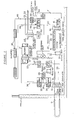
- Figure 1 shows a closed loop 10 of tubing (which can extend either vertical or horizontal), which is filled with anti-freeze and buried in the ground.
- ground heat source
- an alternative form of "ground” heat source can be a well or body of water.
- the present invention can be used with an air heat source, although the latter is less preferred in those locations subject to very low winter temperatures, because some form of auxiliary heating, e.g. a furnace, then becomes necessary.
- the anti-freeze in the loop 10 is circulated by a first pump 11 through a first heat exchanger 12 which is conventional in its construction and serves as an evaporator (in the heating mode) to transfer heat to a refrigerant circuit.
- the refrigerant circuit is charged with a suitable refrigerant, e.g. that known as R-22, R-502, R-12 or R114, and consists principally of a reversing valve 13, a compressor 14, a second heat exchanger 15 and a third heat exchanger 16 which acts either as a desuperheater or as a condenser.
- a suitable refrigerant e.g. that known as R-22, R-502, R-12 or R114
- a suitable refrigerant e.g. that known as R-22, R-502, R-12 or R114
- a suitable refrigerant e.g. that known as R-22, R-502, R-12 or R114
- the second heat exchanger 15 provides thermal linkage between the refrigerant circuit and air forced over the exchanger by a blower 17.
- the third heat exchanger 16 provides thermal linkage between the refrigerant circuit and water circulated by a second pump 18.
- refrigerant flows as shown by solid arrows from the high pressure side of the compressor 14 through a pipe 20 and a muffler 21 to the third heat exchanger 16 which acts as a condenser and extracts heat.
- the refrigerant in liquid phase
- the second heat exchanger 15 which also acts as a condenser to extract further heat (at a lower temperature) and to transfer such heat to the air forced by the blower 17 to heat the building.
- the refrigerant Downstream of the heat exchanger 15, the refrigerant (still in liquid phase) passes in pipes 23, 24 and 25 through a check valve 27, i.e.
- a non-return valve a receiver 28 and a filter dryer 29 (both conventional components in such a system) to a thermostatically controlled first expansion valve 30 and then to the first heat exchanger 12 which forms the evaporator.
- the refrigerant in vapour phase
- a pressurestat 54 is connected to the high pressure side of the compressor 14.
- the reversing valve 13 is reversed, so that the pipe 22 is now connected to the pipe 31 and the refrigerant flows as shown by the broken arrows, i.e. after the valve 13 to the first heat exchanger 12 and then in pipe 33 through a check valve 34, the receiver 28 and the filter dryer 29 to a second thermostatically controlled expansion valve 35 and then in pipe 36 to the second heat exchanger 15 which now acts as the evaporator to extract heat from the forced air.
- the refrigerant returns to the compressor 14 through the reversing valve 13.
- the third heat exchanger 16 extracts heat from the refrigerant, and this action takes place in both the heating and cooling modes.
- This heat is transferred to water circulated by the pump 18.
- This water flows in pipe 40 to the outer jacket of a hot water tank 41 through an automatic, two-way valve 42 and a pipe 43.
- the type of valve used for this purpose is sometimes referred to as a "three-way valve” because it has three ports, but the term "two-way” has been adopted herein to signify that it serves to divert the water flow in one or other of two ways.
- the inner compartment of the tank 41 is connected by pipes 44 and 45 to the cold water main and the outflow to the domestic hot water system, respectively.
- the tank 41 is, in effect, another heat exchanger providing thermal linkage between the hydronic system and the domestic water supply.
- a conventional hot water tank interfacing with the hydronic system through a separate heat exchanger can be used.
- the hot water in pipe 40 is connectable by the valve 42 to a further pipe 46 leading to the hydronic space heating system, namely the radiators 47 in the building.
- Return flow is in pipe 48 through a check valve 49.
- the two-way valve 42 has positions A and B. Position A connects the pumped water to the tank 41, position B to the radiators 47.
- the heated water in pipe 40 can be connected through a manually controllable valve 50 to a fourth heat exchanger 51 for transferring the heat to water circulated in pipes 52, 53 by means of pumps (not shown) to one or more further installations (not shown), such as a swimming pool or hot tub.
- the overall performance of the system is determined by a control panel (not shown) reacting to the usual thermostats. Such performance is as follows:
- the valve 42 When the control panel is set for situation (b), the valve 42 is held in position B and the blower 17 is on. The reversing valve remains deenergised. Heat is then pumped from the first heat exchanger 12 to the third heat exchanger 16, where it is removed at relatively high temperature to feed the hydronic heating system, i.e. radiators 47. Heat also flows to the second heat exchanger 15 where it is removed at a lower temperature to supply the forced air system.
- some distribution systems may have only a forced air or only a hydronic system.
- the system functions the same as in situation (b), except that the position of the valve 42 is no longer set by the control panel, but is determined by the demand from the hot water tank 41.
- the valve 42 When there is demand for heat from the tank 41, it will be given priority and the valve 42 will occupy position A.
- a demand will be comparatively short lived, e.g. 10-30 minutes, and the building will have sufficient thermal inertia to enable it to accept reduced heating for such a period without serious disadvantage while the tank 41 is being reheated.
- valve 50 can be opened by manual control to utilise the fourth heat exchanger 51.
- control device turns on the pumps 11 and 18 and places the valve 42 in the A position, the conditions and function being the same as in situation (a).
- the system can pump heat in basically four different ways:
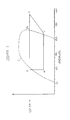
- FIG. 2 shows the phase change curve C and the energy cycle of the refrigerant, i.e. compression (path 1-2), condensing at constant pressure (path 2-3), flashing past the expansion valve (path 3-4) and passing through the evaporator (path 4-1).
- the heat exchanger 16 acts as a desuperheated, it extracts only the heat in the vapour phase, i.e. between points 2 and 2a.
- the heat exchanger 16 extracts all the heat in this part of the cycle, i.e. between points 2 and 3. This latter amount of heat will be typically at least five times more than that between points 2 and 2a.
- the scale along the abscissa is expanded on the right hand side of the drawing compared to the left.
- valve 42 is always in the A position and the heat exchanger 16 acts as a desuperheater. This means that a small amount of heat at high temperture is injected into the hot water tank by convection, as explained in relation to situation (e) above, and the pump 18 is not required to run. This is an important point, because it both saves energy for running the pump 18 and takes advantage of the very high temperature of the superheated gas at the discharge side of the compressor.
- This facility depends, however, on using for the heat exchanger 16 one that is vertically oriented and has a low pressure drop from input to output, i. e. a large surface area.
- Such a heat exchanger has been disclosed in Swedish Patent Application No. 8 101 767 5 of Eric Graryd et. al. filed March 20, 1981 and published September 20, 1982.
- the disclosed heat pump system can be adapted either to a new construction having a forced air system, in which case the hydronic circuit is used only for the hot water supply and any auxiliary equipment, such as a swimming pool; or to the retrofitting of an existing construction already fitted with hot water radiators, in which case it may be necessary to cut some holes in floors and/or walls and install some ducting to accommodate the forced air system.
- the system will, of course, incorporate the usual practical and safety features, such as high and low limit pressurestats on the high and low pressure sides of the compressor, other thermstatic controls and the necessary valves for filling and bleeding the various parts of the system.
Landscapes
- Engineering & Computer Science (AREA)
- Physics & Mathematics (AREA)
- Thermal Sciences (AREA)
- Mechanical Engineering (AREA)
- General Engineering & Computer Science (AREA)
- Chemical & Material Sciences (AREA)
- Combustion & Propulsion (AREA)
- Steam Or Hot-Water Central Heating Systems (AREA)
- Other Air-Conditioning Systems (AREA)
Applications Claiming Priority (2)
| Application Number | Priority Date | Filing Date | Title |
|---|---|---|---|
| CA000438366A CA1214336A (fr) | 1983-10-11 | 1983-10-11 | Thermopompe |
| CA438366 | 1983-10-11 |
Publications (2)
| Publication Number | Publication Date |
|---|---|
| EP0138568A2 true EP0138568A2 (fr) | 1985-04-24 |
| EP0138568A3 EP0138568A3 (fr) | 1986-08-13 |
Family
ID=4126227
Family Applications (1)
| Application Number | Title | Priority Date | Filing Date |
|---|---|---|---|
| EP84306902A Withdrawn EP0138568A3 (fr) | 1983-10-11 | 1984-10-10 | Système de pompe à chaleur |
Country Status (3)
| Country | Link |
|---|---|
| US (1) | US4575001A (fr) |
| EP (1) | EP0138568A3 (fr) |
| CA (1) | CA1214336A (fr) |
Cited By (15)
| Publication number | Priority date | Publication date | Assignee | Title |
|---|---|---|---|---|
| GB2344418A (en) * | 1998-09-01 | 2000-06-07 | David Huw Stephens | A system for heating and ventilating a dwelling using a heat pump |
| AT409667B (de) * | 1994-12-06 | 2002-10-25 | Heinz Groesswang | Einrichtung zur übertragung von kondensationswärme |
| WO2005047781A1 (fr) * | 2003-11-17 | 2005-05-26 | Quantum Energy Technologies Pty Limited | Systeme de pompe thermique destine au chauffage et/ou au refroidissement de l'air et/ou de l'eau |
| GB2414289A (en) * | 2004-05-19 | 2005-11-23 | Asker Barum Kuldeteknikk A S | A heat pump installation |
| US7155922B2 (en) | 2001-12-12 | 2007-01-02 | Quantum Energy Technologies Pty Limited | Energy efficient heat pump systems for water heating and air conditioning |
| EP2103880B1 (fr) * | 2008-03-20 | 2011-09-07 | Daikin Industries, Ltd. | Dispositif de chauffage et procédé de contrôle du chauffage |
| US20120280052A1 (en) * | 2010-03-05 | 2012-11-08 | Mitsubishi Heavy Industries, Ltd. | Hot-water heat pump and method of controlling the same |
| EP2339245A3 (fr) * | 2009-12-23 | 2013-11-13 | Waterkotte GmbH | Dispositifs de chauffage et de refroidissement dotés d'une pompe à chaleur |
| ITBZ20120025A1 (it) * | 2012-06-04 | 2013-12-05 | Johann Beltrami | Impianto trasportante, convertente e erogante energia termica. |
| EP2972008A4 (fr) * | 2013-03-13 | 2016-11-09 | Rheem Mfg Co | APPAREIL ET PROCÉDÉS POUR LE PRÉCHAUFFAGE D'EAU AVEC UNE UNITÉ DE CLIMATISATION OU UNE POMPE À EAU& xA; |
| US9945587B2 (en) | 2014-09-02 | 2018-04-17 | Rheem Manufacturing Company | Apparatus and method for hybrid water heating and air cooling and control thereof |
| CN112594761A (zh) * | 2020-11-11 | 2021-04-02 | 华电电力科学研究院有限公司 | 一种集中式区域供能方法 |
| CN112944429A (zh) * | 2021-02-02 | 2021-06-11 | 珠海格力电器股份有限公司 | 一种热泵机组及其控制方法 |
| US12173909B2 (en) | 2020-07-13 | 2024-12-24 | Rheem Manufacturing Company | Integrated space conditioning and water heating/cooling systems and methods thereto |
| US12449139B2 (en) | 2020-11-02 | 2025-10-21 | Rheem Manufacturing Company | Combined space and water heating systems |
Families Citing this family (24)
| Publication number | Priority date | Publication date | Assignee | Title |
|---|---|---|---|---|
| JPS63118546A (ja) * | 1986-11-05 | 1988-05-23 | Takenaka Komuten Co Ltd | ビル空調システム |
| SE464667B (sv) * | 1988-08-22 | 1991-05-27 | Thermia Ab | Vaermepumpanlaeggning foer uppvaermning eller kylning av utrymmen samt uppvaermning av tappvarmvatten |
| EP0431491A1 (fr) * | 1989-12-06 | 1991-06-12 | Kabushiki Kaisha Toshiba | Appareil de chauffage du type pompe à chaleur et méthode pour contrôler cet appareil |
| US5351502A (en) * | 1991-10-30 | 1994-10-04 | Lennox Industries, Inc. | Combination ancillary heat pump for producing domestic hot h20 with multimodal dehumidification apparatus |
| CA2121794A1 (fr) * | 1991-10-30 | 1993-05-13 | Theodore C. Gilles | Thermopompe auxiliaire destinee a produire de l'eau chaude pour usage domestique |
| US5558273A (en) * | 1994-11-10 | 1996-09-24 | Advanced Mechanical Technology, Inc. | Two-pipe system for refrigerant isolation |
| US5806331A (en) * | 1995-08-07 | 1998-09-15 | Waterfurnace International, Inc. | Water-based hot water heat pump |
| GB0104636D0 (en) * | 2001-02-26 | 2001-04-11 | Stephens David H | Reduction of carbon dioxide emissions caused by buildings |
| US20080264075A1 (en) * | 2004-05-12 | 2008-10-30 | Electro Industries, Inc. | Heat pump system with extended run time boost compressor |
| US20080098760A1 (en) * | 2006-10-30 | 2008-05-01 | Electro Industries, Inc. | Heat pump system and controls |
| US20070079436A1 (en) * | 2005-10-10 | 2007-04-12 | Byeongchul Na | Spa Heating and Cooling System |
| US20070205292A1 (en) * | 2006-03-01 | 2007-09-06 | Kyung Dong Boiler Co. Ltd. | Heated fluid distribution apparatus for combined domestic hot water supply and space heating system |
| EP2103879B1 (fr) * | 2008-03-20 | 2015-07-29 | Daikin Industries, Ltd. | Dispositif de chauffage |
| US8385729B2 (en) | 2009-09-08 | 2013-02-26 | Rheem Manufacturing Company | Heat pump water heater and associated control system |
| FR2956194A1 (fr) * | 2010-02-09 | 2011-08-12 | Didier Cheron | Chauffage pour spa par aerothermie et geothermie |
| US9052125B1 (en) | 2011-09-08 | 2015-06-09 | Dennis S. Dostal | Dual circuit heat pump |
| US10119738B2 (en) | 2014-09-26 | 2018-11-06 | Waterfurnace International Inc. | Air conditioning system with vapor injection compressor |
| SE541234C2 (en) * | 2015-11-20 | 2019-05-07 | Sens Geoenergy Storage Ab | Methods and systems for heat pumping |
| US10871314B2 (en) | 2016-07-08 | 2020-12-22 | Climate Master, Inc. | Heat pump and water heater |
| US10866002B2 (en) | 2016-11-09 | 2020-12-15 | Climate Master, Inc. | Hybrid heat pump with improved dehumidification |
| US10935260B2 (en) | 2017-12-12 | 2021-03-02 | Climate Master, Inc. | Heat pump with dehumidification |
| US11592215B2 (en) | 2018-08-29 | 2023-02-28 | Waterfurnace International, Inc. | Integrated demand water heating using a capacity modulated heat pump with desuperheater |
| CA3081986A1 (fr) | 2019-07-15 | 2021-01-15 | Climate Master, Inc. | Systeme de conditionnement d`air a regulation de puissance et production d`eau chaude controlee |
| US12181189B2 (en) | 2021-11-10 | 2024-12-31 | Climate Master, Inc. | Ceiling-mountable heat pump system |
Family Cites Families (10)
| Publication number | Priority date | Publication date | Assignee | Title |
|---|---|---|---|---|
| DE2637209A1 (de) * | 1976-08-18 | 1978-02-23 | Bosch Gmbh Robert | Heizungsanlage mit einer waermepumpe |
| US4098092A (en) * | 1976-12-09 | 1978-07-04 | Singh Kanwal N | Heating system with water heater recovery |
| US4270359A (en) * | 1978-12-07 | 1981-06-02 | Hummel Steven L | Solar heating system |
| US4308723A (en) * | 1979-06-21 | 1982-01-05 | Atlantic Richfield Company | Heat pump employing optimal refrigerant compressor for low pressure ratio applications |
| GB2067275B (en) * | 1979-11-22 | 1984-06-06 | Trendpam Eng Ltd | Combined refrigeration and heating system |
| US4327561A (en) * | 1980-06-20 | 1982-05-04 | Mcneal G Russell | High coefficient of performance heat pump |
| US4375831A (en) * | 1980-06-30 | 1983-03-08 | Downing Jr James E | Geothermal storage heating and cooling system |
| US4299098A (en) * | 1980-07-10 | 1981-11-10 | The Trane Company | Refrigeration circuit for heat pump water heater and control therefor |
| SE441303B (sv) * | 1981-03-20 | 1985-09-23 | Thermia Verken Ab | Vermevexlare med parallella ror med rektangulert tversnitt med hoppressningar pa bestemda avstand, vilka tjena som distanselement |
| US4399664A (en) * | 1981-12-07 | 1983-08-23 | The Trane Company | Heat pump water heater circuit |
-
1983
- 1983-10-11 CA CA000438366A patent/CA1214336A/fr not_active Expired
-
1984
- 1984-10-10 EP EP84306902A patent/EP0138568A3/fr not_active Withdrawn
-
1985
- 1985-05-29 US US06/738,903 patent/US4575001A/en not_active Expired - Fee Related
Cited By (28)
| Publication number | Priority date | Publication date | Assignee | Title |
|---|---|---|---|---|
| AT409667B (de) * | 1994-12-06 | 2002-10-25 | Heinz Groesswang | Einrichtung zur übertragung von kondensationswärme |
| GB2344418B (en) * | 1998-09-01 | 2003-04-02 | David Huw Stephens | Heating and ventilation of dwellings |
| GB2344418A (en) * | 1998-09-01 | 2000-06-07 | David Huw Stephens | A system for heating and ventilating a dwelling using a heat pump |
| US7155922B2 (en) | 2001-12-12 | 2007-01-02 | Quantum Energy Technologies Pty Limited | Energy efficient heat pump systems for water heating and air conditioning |
| WO2005047781A1 (fr) * | 2003-11-17 | 2005-05-26 | Quantum Energy Technologies Pty Limited | Systeme de pompe thermique destine au chauffage et/ou au refroidissement de l'air et/ou de l'eau |
| GB2414289A (en) * | 2004-05-19 | 2005-11-23 | Asker Barum Kuldeteknikk A S | A heat pump installation |
| EP2103880B1 (fr) * | 2008-03-20 | 2011-09-07 | Daikin Industries, Ltd. | Dispositif de chauffage et procédé de contrôle du chauffage |
| AU2009227388B2 (en) * | 2008-03-20 | 2012-03-01 | Daikin Europe N.V. | Heating and method for controlling the heating |
| AU2009227388B8 (en) * | 2008-03-20 | 2012-03-22 | Daikin Europe N.V. | Heating and method for controlling the heating |
| KR101252786B1 (ko) * | 2008-03-20 | 2013-04-09 | 다이킨 유럽 엔.브이. | 난방 장치 및 난방 장치를 제어하기 위한 방법 |
| EP2339245A3 (fr) * | 2009-12-23 | 2013-11-13 | Waterkotte GmbH | Dispositifs de chauffage et de refroidissement dotés d'une pompe à chaleur |
| US9664415B2 (en) * | 2010-03-05 | 2017-05-30 | Mitsubishi Heavy Industries, Ltd. | Hot-water heat pump and method of controlling the same |
| US20120280052A1 (en) * | 2010-03-05 | 2012-11-08 | Mitsubishi Heavy Industries, Ltd. | Hot-water heat pump and method of controlling the same |
| ITBZ20120025A1 (it) * | 2012-06-04 | 2013-12-05 | Johann Beltrami | Impianto trasportante, convertente e erogante energia termica. |
| CN108088114B (zh) * | 2013-03-13 | 2020-08-21 | 瑞美制造公司 | 采用来自空气调节系统的制冷剂加热水的装置和方法 |
| US10871307B2 (en) | 2013-03-13 | 2020-12-22 | Rheem Manufacturing Company | Apparatus and methods for heating water with refrigerant from air conditioning system |
| US9945582B2 (en) | 2013-03-13 | 2018-04-17 | Rheem Manufacturing Company | Apparatus and methods for pre-heating water with air conditioning unit or heat pump |
| US12203683B2 (en) | 2013-03-13 | 2025-01-21 | Rheem Manufacturing Company | Apparatus and methods for heating water with refrigerant from air conditioning system |
| CN108088114A (zh) * | 2013-03-13 | 2018-05-29 | 瑞美制造公司 | 采用来自空气调节系统的制冷剂加热水的装置和方法 |
| US9879881B2 (en) | 2013-03-13 | 2018-01-30 | Rheem Manufacturing Company | Apparatus and methods for heating water with refrigerant from air conditioning system |
| EP2972008A4 (fr) * | 2013-03-13 | 2016-11-09 | Rheem Mfg Co | APPAREIL ET PROCÉDÉS POUR LE PRÉCHAUFFAGE D'EAU AVEC UNE UNITÉ DE CLIMATISATION OU UNE POMPE À EAU& xA; |
| US10041702B2 (en) | 2014-09-02 | 2018-08-07 | Rheem Manufacturing Company | Apparatus and method for hybrid water heating and air cooling and control thereof |
| US9945587B2 (en) | 2014-09-02 | 2018-04-17 | Rheem Manufacturing Company | Apparatus and method for hybrid water heating and air cooling and control thereof |
| US12173909B2 (en) | 2020-07-13 | 2024-12-24 | Rheem Manufacturing Company | Integrated space conditioning and water heating/cooling systems and methods thereto |
| US12449139B2 (en) | 2020-11-02 | 2025-10-21 | Rheem Manufacturing Company | Combined space and water heating systems |
| CN112594761A (zh) * | 2020-11-11 | 2021-04-02 | 华电电力科学研究院有限公司 | 一种集中式区域供能方法 |
| CN112944429A (zh) * | 2021-02-02 | 2021-06-11 | 珠海格力电器股份有限公司 | 一种热泵机组及其控制方法 |
| CN112944429B (zh) * | 2021-02-02 | 2022-03-15 | 珠海格力电器股份有限公司 | 一种热泵机组及其控制方法 |
Also Published As
| Publication number | Publication date |
|---|---|
| EP0138568A3 (fr) | 1986-08-13 |
| CA1214336A (fr) | 1986-11-25 |
| US4575001A (en) | 1986-03-11 |
Similar Documents
| Publication | Publication Date | Title |
|---|---|---|
| US4575001A (en) | Heat pump system | |
| KR102161125B1 (ko) | 지능형 이중 열교환 방식의 히트펌프 시스템 | |
| US5239838A (en) | Heating and cooling system having auxiliary heating loop | |
| US9822996B2 (en) | Additive heat unit for HVAC heat pump system | |
| US4314456A (en) | Refrigerant condensing system | |
| GB2247072A (en) | Heating or cooling system | |
| GB1564740A (en) | Air-conditioning apparatus | |
| GB2026672A (en) | Heat pump system selectively operable in a cascade mode | |
| AU2016253585B2 (en) | Solar hot water and recovery system | |
| JPH033868B2 (fr) | ||
| US4754614A (en) | Prime-motor-driven room warming/cooling and hot water supplying apparatus | |
| US10941965B2 (en) | System and method for providing supplemental heat to a refrigerant in an air-conditioner | |
| JPS6155018B2 (fr) | ||
| RU2319078C2 (ru) | Система кондиционирования воздуха для помещений | |
| GB2102929A (en) | Heat pump unit | |
| JP4809055B2 (ja) | エアコン他機能付加装置 | |
| RU2808026C1 (ru) | Теплонасосная установка | |
| DK159738B (da) | Kombineret koele- og varmeanlaeg | |
| EP1420218B1 (fr) | Refroidisseur épargnant de la chaleur | |
| CN202501663U (zh) | 一种双系统无氟节能空气源热泵多用机 | |
| JP2009109061A (ja) | 暖房パネルを備えたヒートポンプ式空調装置 | |
| JP3690155B2 (ja) | 冷温水供給装置 | |
| JPH0252789B2 (fr) | ||
| JPH0125982B2 (fr) | ||
| JPH0123089Y2 (fr) |
Legal Events
| Date | Code | Title | Description |
|---|---|---|---|
| PUAI | Public reference made under article 153(3) epc to a published international application that has entered the european phase |
Free format text: ORIGINAL CODE: 0009012 |
|
| AK | Designated contracting states |
Designated state(s): BE DE FR GB IT NL SE |
|
| PUAL | Search report despatched |
Free format text: ORIGINAL CODE: 0009013 |
|
| AK | Designated contracting states |
Kind code of ref document: A3 Designated state(s): BE DE FR GB IT NL SE |
|
| STAA | Information on the status of an ep patent application or granted ep patent |
Free format text: STATUS: THE APPLICATION IS DEEMED TO BE WITHDRAWN |
|
| 18D | Application deemed to be withdrawn |
Effective date: 19870414 |
|
| RIN1 | Information on inventor provided before grant (corrected) |
Inventor name: SANTANGELO, SALVATORE Inventor name: OSKARSSON, SVEN GUNNAR |