EP0138571A2 - Mit Rädern ausgerüstete Vorrichtung - Google Patents
Mit Rädern ausgerüstete Vorrichtung Download PDFInfo
- Publication number
- EP0138571A2 EP0138571A2 EP84306908A EP84306908A EP0138571A2 EP 0138571 A2 EP0138571 A2 EP 0138571A2 EP 84306908 A EP84306908 A EP 84306908A EP 84306908 A EP84306908 A EP 84306908A EP 0138571 A2 EP0138571 A2 EP 0138571A2
- Authority
- EP
- European Patent Office
- Prior art keywords
- frame
- ground
- leg
- leg frame
- mechanism according
- Prior art date
- Legal status (The legal status is an assumption and is not a legal conclusion. Google has not performed a legal analysis and makes no representation as to the accuracy of the status listed.)
- Granted
Links
- 230000008901 benefit Effects 0.000 description 7
- 239000007789 gas Substances 0.000 description 6
- 238000003466 welding Methods 0.000 description 4
- 238000005096 rolling process Methods 0.000 description 3
- 238000003860 storage Methods 0.000 description 3
- ATUOYWHBWRKTHZ-UHFFFAOYSA-N Propane Chemical compound CCC ATUOYWHBWRKTHZ-UHFFFAOYSA-N 0.000 description 2
- 230000000881 depressing effect Effects 0.000 description 2
- 238000006073 displacement reaction Methods 0.000 description 2
- 230000000694 effects Effects 0.000 description 2
- 230000005484 gravity Effects 0.000 description 2
- 239000000463 material Substances 0.000 description 2
- 230000000284 resting effect Effects 0.000 description 2
- HSFWRNGVRCDJHI-UHFFFAOYSA-N alpha-acetylene Natural products C#C HSFWRNGVRCDJHI-UHFFFAOYSA-N 0.000 description 1
- QVGXLLKOCUKJST-UHFFFAOYSA-N atomic oxygen Chemical compound [O] QVGXLLKOCUKJST-UHFFFAOYSA-N 0.000 description 1
- 238000006243 chemical reaction Methods 0.000 description 1
- 238000010276 construction Methods 0.000 description 1
- 230000003028 elevating effect Effects 0.000 description 1
- QFXZANXYUCUTQH-UHFFFAOYSA-N ethynol Chemical group OC#C QFXZANXYUCUTQH-UHFFFAOYSA-N 0.000 description 1
- 125000002534 ethynyl group Chemical group [H]C#C* 0.000 description 1
- 238000004519 manufacturing process Methods 0.000 description 1
- 239000001301 oxygen Substances 0.000 description 1
- 229910052760 oxygen Inorganic materials 0.000 description 1
- 239000004033 plastic Substances 0.000 description 1
- 229920003023 plastic Polymers 0.000 description 1
- 239000001294 propane Substances 0.000 description 1
- 230000000452 restraining effect Effects 0.000 description 1
- XLYOFNOQVPJJNP-UHFFFAOYSA-N water Substances O XLYOFNOQVPJJNP-UHFFFAOYSA-N 0.000 description 1
Images


Classifications
-
- B—PERFORMING OPERATIONS; TRANSPORTING
- B62—LAND VEHICLES FOR TRAVELLING OTHERWISE THAN ON RAILS
- B62B—HAND-PROPELLED VEHICLES, e.g. HAND CARTS OR PERAMBULATORS; SLEDGES
- B62B1/00—Hand carts having only one axis carrying one or more transport wheels; Equipment therefor
- B62B1/10—Hand carts having only one axis carrying one or more transport wheels; Equipment therefor in which the load is intended to be transferred totally to the wheels
- B62B1/14—Hand carts having only one axis carrying one or more transport wheels; Equipment therefor in which the load is intended to be transferred totally to the wheels involving means for grappling or securing in place objects to be carried; Loading or unloading equipment
Definitions
- the present invention relates to a wheeled mechanism which may be formed as a load-bearing trolley for general purpose use or for one of a range of special purposes, or may be adapted as a support frame for assistance with walking.
- sack-barrow comprises a rigid L-shape frame with a pair of wheels pivoted at the intersection of two approximately orthogonal arms of the frame.
- the horizontal arm is very much shorter than the vertical arm and this latter has a pair of handles at the upper end, or a loop by which the barrow can be manipulated.
- Such barrows have the disadvantage that loading and unloading involves tipping the load in order to introduce the platform constituted by the horizontal arm of the L-shape frame.
- the weight of the load is to a large extent carried by the operator through the handle, particularly if the frame is inclined at a substantial angle to the vertical in operation, and there is a risk that the load will tip and fall off if the load bearing platform is placed on the ground, for example, to allow the operator to rest.
- Other known trollies include a trolley having four wheels, two of which are steerable, and which provides a loud-bearing platform on a frame spanning the wheels. Such a trolley is complex, expensive and difficult to manoeuvre. Although a sack-barrow is of simple construction, it is difficult to operate and requires great strength of the user.
- the present invention seeks to provide a wheeled mechanism which can be used as a load bearing trolley or barrow and which will not suffer from the disadvantages of the known sack-barrow and at the same time will be simpler and more economical to manufacture than known four- wheeled trolleys.
- a wheeled mechanism for transporting a load or for other purposes characterised in that it comprises a frame having at least two ground wheels mounted thereon so as to be turnable about a common axis, and an operating handle, a substantially rigid leg frame or member being pivotally mounted at or adjacent one end thereof on the frame to turn about a second pivot axis substantially parallel to the said common axis, the length of the said leg frame or member being such that the end thereof remote from the said second pivot axis is engageable on the ground in a first relative orientation of the leg frame or member and the frame, and can be raised from the ground upon relative turning movement of the leg frame or member and the frame about the said second axis.
- the legs frame or member With the leg frame or member raised from the ground the wheels of the mechanism can be rolled in a conventional manner to allow the mechanism to be moved freely and easily from place to place.
- the leg frame or member may be provided with a support platform or container and it is a particular feature of the present invention that the leg frame or member is movable between a first and a second position with respect to the main support frame and in the second position the support surface of the platform or container is generally parallel with the ground so that any load requiring it can be maintained in a strictly upright orientation.
- Known trolleys of the sack-barrow type have inevitably tilted the load in order to make it possible for the load to be raised from the ground.
- the operating handle may be linked to the main support frame by a cranked portion thereof so that the operating handle is positioned spaced from a vertical plane including the axis thereof in a direction away from the support platform or container so that the leverage which can be applied by the handle is sufficiently great to be able to control even substantial loads on the platform or container without requiring the application of a very great force at the handle.
- relative movement between the main support frame and the leg frame or member is limited by abutment stop means to determine the said first relative position.
- abutment stop means In this first relative position the ground-engaging end of the leg frame or member is in contact with the ground and movement of the handle in the same direction as displacement between the second position and the first position is prevented by such abutment stop means, forces exerted on the handle being transferred to the ground through the ground-engaging means.
- the ground-engaging member instead of being formed as a platform or container, is formed as a foot having frictional properties in order to increase the frictional resistance between the foot and the ground.
- Such properties may be provided, for example, by suitably covering the ground-engaging surface of the foot with rubber or plastics material having an appropriate coefficient of friction.
- the operating handle may be provided as a U-shape partially encircling the body of the user. Then, by rocking the support handle towards the user the ground-engaging foot can be released from the ground allowing the wheels to roll so that the invalid can walk partly supported by the rolling wheels: in such circumstances it is envisaged that the ground-engaging foot will still be slightly in contact with the ground so that a degree of frictional resistance which can be controlled by the operator acting on the handle, can be maintained for control purposes. When required it is only necessary then to push the handle slightly away from the body of the operator in order to re-engage the ground-engaging foot on the ground so that the whole weight of the operator can be allowed to rest on the support frame which, conveniently, is located just below elbow height.
- an additional ground-engaging foot may be provided on the other side of the axis of the wheels of the main frame.
- the wheels may then only roll when a balance position between two terminal positions is achieved and tilting of the operating handle to either side of this balance position, beyond a certain angle, will result in one or other of the two ground-engaging feet coming into contact with the ground and preventing further rolling movement of the wheels whilst at the same time providing support on which an operator may lean.
- Embodiments of the present invention may also be made for special purposes, for example, a trolley may be formed for carrying and supporting gas bottles such as propane or oxygen and acetylene bottles such as are used for welding.
- the leg frame or member is formed as a frame with a support platform for the gas bottles and restraining means at the top and bottom to ensure that they are held to this frame.
- Such a releaseable pivotal connection may be made, for example, by suitable hook shape engagement members on the frame, which can be released upon displacement of the leg frame from the first to the second position in which the leg member engages the ground; in this position the wheels of the frame may be spaced from the ground thereby leaving available movement in a vertical direction.
- the present invention also comprehends a wheeled mechanism as defined above formed as a trolley with means for receiving an enlarged platform removably attachable to the leg frame or member.
- enlarged platform may be suitable, for example, for retaining a dustbin or like dimensioned article, and has the advantage that, with the platform flat on the ground it can be moved under the dustbin by sliding, and subsequently raised without tilting the dustbin simply by displacing the frame from the second to the first position. In the first position the platform is held by the frame spaced a short distance from the ground and in a horizontal plane.
- the platform can be tilted to move the centre of gravity of the article supported thereby more closely towards the axis of the ground wheels.
- the operating handle is spaced from the vertical plane including the axis of the ground wheels when the mechanism is in the said first position, additional leverage for manipulating such weight is readily available without requiring the operator to exert a large force.
- the load-bearing platform may be removeable or may be pivotally connected to the leg member or frame constituting the leg member to allow it to be folded flat against the frame.
- the operating handle may be formed such that it can be folded flat or telescoped within a part of the frame.
- embodiments of the present invention may also be made with a seat fixed to or attachable to the leg member or frame constituting the leg member for use as a baby carriage for supporting and transporting infants.
- a seat fixed to or attachable to the leg member or frame constituting the leg member for use as a baby carriage for supporting and transporting infants.
- the trolley illustrated is generally indicated with the reference numeral 11 and comprises a generally U-shape main frame 12 having arms 13, 14 joined at their free ends by an axle 15 carrying two wheels 16, 17, one at each end.
- the telescopic handle extension 19 has a plurality of holes 21 and the column 18 has a spring loaded plunger 22 engaged selectively in one of the holes 21 to determine the effective length of the handle extension 19 by selection of its projection distance from the column 18.
- the height of the transverse handle 20 above the ground can thus be easily adjusted. Alternative adjustment systems are also possible, however.
- a cross beam 23 pivoted about an axis X-X at each end to a respective arm 13,14 and having two downwardly divergent support legs 24,25 to the lower end of which is secured a platform generally indicated 26 in the form of a shallow tray having a flat bottom 27 and left and right sides 28,29 and an upright back 30.
- the interconnection between the legs 24,25 and the platform 26 is made by welding or bolting the lower ends of the elgs 24,25 to the side walls 28,29 respectively in such a way that a rigid interconnection at a predetermined fixed angle between the plane of the platform bottom 27 and the plane defined by the two legs 24,2 5 is obtained.
- the side walls 28,29 are each formed as a very small lip over most of the length of the side, with an enlarged rear panel for attachment to the associated leg 24 or 25. This allows a large object to be placed across the platform 26 resting on the upper edges of the side walls 28,29.
- the platform is pivotally mounted to the legs 24, 25, such as by pivot pins, in such a way that it can be folded flat for storage.
- the two arms 13,14 of the U-shape main frame 12 are spanned by a curved strap 31 which serves as an abutment to limit the pivotal movement of the legs 24,25 about the cross member 23. Movement of these legs 24,25 in the opposite direction is limited by abutment of the platform tray or the legs themselves against the axle 15.
- the effect of the limited articulation ofthe sub-frame constituted by the legs 24,25 and the cross member 23 with respect to the U-shape main frame 12 wal be described hereinbelow with reference to Figures 2,3 and 4.
- the legs 24,25 are replaced by a single leg extending from the cross members 23 to the platform 26.
- the trolley is shown in a first position with the platform 26 flat on the ground.
- the main frame 12 has been turned about the cross member 23, in a clockwise direction as viewed in Figure 2, to its maximum extent; the arms 13,14 of the main frame 12 have turned about the pivot constituted by the cross piece 23 until with the wheels 16,17 still on the ground, the pan 26 now rests flat on the ground.
- the strap 31 has been brought into contact with the legs 24,25 of the sub-frame, therefore preventing any further movement of the handle 20 and locking the mechanism with the upright column 18 and handle extension 19 at their highest position almost parallel with the legs 24,25 of - the sub-fr ame.
- the handle 20 is horizontally displaced, in this third position, by a distance D from the vertical centre line through the wheels 16, 17 which is greater than the distance d of the assumed centre of gravity at the centre of the platform 26 of any load carried thereby.
- This leverage D/d gives the operator a mechanical advantage in handling the trolley, even with a substantial load on the platform 26.
- the distance D is also shown in Figure 3 to illustrate the distance moved by the handle 20 in raising the front edge of the platform 26 to the horizontal position.
- the movement of the handle 20 to convert the mechanism from the position illustrated in Figure 4 to that illustrated in Figure 2 is relatively small and easily accomplished so that an operator can lower the load onto the ground and even allow his or her own weight to rest on the handle 20 if desired.
- the platform 26 rests flat on the ground in the position illustrated in Figure 2 it can easily be loaded by sliding the load onto the bottom wall 27 of the platform 26 or by pushing the trolley to introduce the bottom wall 27 under the load. Should it be necessary to maintain the load vertical, for example, if this were a bucket of water or the like, this can readily be achieved by holding the trolley in the position of Figure 4 as it is moved along.
- the handle can be moved further in an anti-clockwise direction in order to tilt the platform 26 so that a part of the load, for example if this were a sack or other heavier load, can be borne by the main frame 12 and balanced by the inclination of this with respect to the vertical.
- the platform 26 may be pivotally mounted to the support arms 24, 25 in order to allow it to be folded for storage. Suitable abutment means (not shown) would be provided to locate the platform 26 in the working position illustrated in Figure 1, and the pivotal connection would allow it to be turned until the platform 26 is approximately parallel with the legs 24, 25 so that the front to back dimension of the trolley is reduced substantially.
- the platform 26 would be replaced by a ground-engaging foot having a suitable ground-engaging area and of a material having a high coefficient of friction on the lower face, and the handle 20 could be replaced with a generally U-shape frame having horizontal arms which would pass to either side of the body of a person standing immediately behind the handle 20 so that support in three directions is available.
- the frame can be moved by depressing the handle 20 until the mechanism is in the position illustrated in Figure 4 where the user can then walk rolling the frame before him until such time as a further period of rest is needed when simply by moving the handle upwards and forwardly the locked ground-engaging position is achieved.
- the trolley could roll away from an elderly or infirm user whose reactions are not very fast.
- the embodiment formed as a walking frame may be further modified by the provision of secondary or subsidiary legs near the lower ends of the legs 24, 25 which legs project over the axle 15 and are attached to a second ground-engaging foot which contacts the ground on the other side of the line of contact between the wheels 16, 17 and the ground from the ground-engaging foot attached to the legs 24, 25.
- the wheels 16, 17 will roll only when the handle 20 is located in an intermediate position where the two ground-engaging feet are spaced from the ground and movement in either direction away from this central position will cause the mechanism to become grounded and rigid. Movement can then only take place when the operator is balanced and in control and should any unbalance or lack of control occur then the mechanism will automatically adopt a safety position where it will support the weight of a user resting on the handle.
- FIG. 5 the embodiment illustrated has features in common with the embodiments of Figures 1 - 4 and corresponding or identical parts will be identified with the same reference numerals raised by 100.
- This embodiment differs from the embodiment previously described in that the legs 124, 125 connected to the cross member 123 are not joined at their bottom end by a platform or tray, but by a lower cross member 140, on which are pivotally mounted two T-section supports 141, 142 having cranked end sections 143, 144 respectively at the pivoted end.
- a stop bar 145 also spans the legs 124, 125 just above the cross member 140 and limits the pivotal movement of the members 141, 142 by engagement of the cranked end sections 143, 144.
- the two support members 141, 142 can be used to carry any odd shaped article, or may themselves support a platform or one of a range of different platforms of different sizes specifically adapted for mounting thereon.
- the particular value of the two linear support members 141, 142 is for enabling the trolley to be used to carry a conventional pallett on which any range of goods may be stacked.
- the trolley 111 operates in the same way as described for the embodiment of Figures 1 - 4 with the linear support members 141,142 lowered on the ground and the handle 120 raised, these members can be introduced into the space beneath the load-bearing platform of a pallett.
- the sub-frame constituted by the legs 124, 125 and the cross member 123 is raised from the ground, elevating the platform supports 141, 142 and enabling a pallett supported thereby to be grans- ported in a substantially horizontal orientation to any convenient location.
- interchangeable special purpose platforms or supports may also be provided for the embodiments of Figures 1 - 4, for example, to adapt this embodiment for carrying a dustbin which may be too large to fit on the platform 26 illustrated in Figure 1.
- Such an adaptor may simply interengage on the legs 24,25 and rest on the platform 26.
- the platform 26 may be pivotally connected to the legs 24,25 instead of being fixedly connected as shown, so that the platform bottom 27 may be tipped to a position lying generally parallel to the plane defined by the legs 24,25.
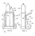
- a trolley adapted to carry gas bottles such as are used for oxy-acetylene welding equipment.
- gas bottles such as are used for oxy-acetylene welding equipment.
- a main frame 212 is shown carried on ground-engaging wheels 216,217 and pivotally connected to a sub-frame incorporating legs 224,225.
- the legs 224,225 are joined at the top by a cross member 246 and an encircling strap 241, and at the bottom by a shallow tray-like container 242 which together act to retain two gas bottles 243, 244 in position on the sub-frame.
- the main frame 212 has a handle 220 which is formed as a loop handle spanning the legs 213,214 which have upward extensions 213a, 214a pivotally connected to the legs 224,225 by pivots 260,261.
- This pivotal interconnection between the main frame 212 and the sub-frame comprising the legs 224,225 is a releasable connection, however, so that the main frame 212 can be released and removed leaving the gas bottles 243,244 standing on the tray 242 in an upright orientation.
- This embodiment has particular advantages since it allows the main frame with its wheels to be removed away from the working environment where the welding is to take place so that it does not constitute an encumbrance, and, indeed, this may be used for transporting other articles in combination with a suitably shaped sub-frame connectable thereto. Further, owing to the great weight of the gas bottles when fully charged, the trolley of the invention has particular advantages in providing additional leverage for control and in not requiring the bottles to be tilted to a steep angle before a balance position is reached.
Landscapes
- Engineering & Computer Science (AREA)
- Chemical & Material Sciences (AREA)
- Combustion & Propulsion (AREA)
- Transportation (AREA)
- Mechanical Engineering (AREA)
- Handcart (AREA)
- Motorcycle And Bicycle Frame (AREA)
- Chair Legs, Seat Parts, And Backrests (AREA)
- Catching Or Destruction (AREA)
- Yarns And Mechanical Finishing Of Yarns Or Ropes (AREA)
- Vehicle Body Suspensions (AREA)
Priority Applications (1)
| Application Number | Priority Date | Filing Date | Title |
|---|---|---|---|
| AT84306908T ATE50743T1 (de) | 1983-10-13 | 1984-10-10 | Mit raedern ausgeruestete vorrichtung. |
Applications Claiming Priority (2)
| Application Number | Priority Date | Filing Date | Title |
|---|---|---|---|
| GB838327363A GB8327363D0 (en) | 1983-10-13 | 1983-10-13 | Wheeled mechanism |
| GB8327363 | 1983-10-13 |
Publications (3)
| Publication Number | Publication Date |
|---|---|
| EP0138571A2 true EP0138571A2 (de) | 1985-04-24 |
| EP0138571A3 EP0138571A3 (en) | 1986-01-08 |
| EP0138571B1 EP0138571B1 (de) | 1990-03-07 |
Family
ID=10550100
Family Applications (1)
| Application Number | Title | Priority Date | Filing Date |
|---|---|---|---|
| EP84306908A Expired - Lifetime EP0138571B1 (de) | 1983-10-13 | 1984-10-10 | Mit Rädern ausgerüstete Vorrichtung |
Country Status (4)
| Country | Link |
|---|---|
| EP (1) | EP0138571B1 (de) |
| AT (1) | ATE50743T1 (de) |
| DE (1) | DE3481503D1 (de) |
| GB (1) | GB8327363D0 (de) |
Cited By (2)
| Publication number | Priority date | Publication date | Assignee | Title |
|---|---|---|---|---|
| FR2642388A1 (fr) * | 1989-02-02 | 1990-08-03 | Lyon Communaute Urbaine | Diable pour la manutention de recipients munis de roues |
| FR2797837A1 (fr) * | 1999-08-25 | 2001-03-02 | Grinand Sa | Chariot porte container |
Families Citing this family (2)
| Publication number | Priority date | Publication date | Assignee | Title |
|---|---|---|---|---|
| USD588318S1 (en) | 2008-01-28 | 2009-03-10 | American Safety Razor | Floor stripper |
| DE102013100449B4 (de) * | 2013-01-17 | 2025-07-03 | Hans-Dieter Früchtenicht | Flurförderzeug für Paletten |
Family Cites Families (7)
| Publication number | Priority date | Publication date | Assignee | Title |
|---|---|---|---|---|
| GB566932A (en) * | 1943-07-03 | 1945-01-19 | Francis & Barnett Ltd | Improvements in trucks or barrows |
| DE815448C (de) * | 1949-11-13 | 1951-10-01 | Hans Meier | Zweiraedrige Transportvorrichtung, insbesondere fuer Milchkannen |
| GB677567A (en) * | 1950-03-09 | 1952-08-20 | Strachan & Henshaw Ltd | Improvements in or relating to trolleys for handling and/or transporting packages |
| FR1339773A (fr) * | 1962-11-06 | 1963-10-11 | Chariot pour le transport de récipients ou cadres, et récipients ou cadres utilisables avec ledit chariot | |
| US3247989A (en) * | 1963-07-08 | 1966-04-26 | M Antonio Uribe | Barrel truck |
| FR2057544A5 (de) * | 1969-08-27 | 1971-05-21 | Manss Fa August | |
| FR2120459A5 (de) * | 1971-01-04 | 1972-08-18 | Mounier Gle Etirage Tube |
-
1983
- 1983-10-13 GB GB838327363A patent/GB8327363D0/en active Pending
-
1984
- 1984-10-10 AT AT84306908T patent/ATE50743T1/de not_active IP Right Cessation
- 1984-10-10 DE DE8484306908T patent/DE3481503D1/de not_active Expired - Lifetime
- 1984-10-10 EP EP84306908A patent/EP0138571B1/de not_active Expired - Lifetime
Cited By (2)
| Publication number | Priority date | Publication date | Assignee | Title |
|---|---|---|---|---|
| FR2642388A1 (fr) * | 1989-02-02 | 1990-08-03 | Lyon Communaute Urbaine | Diable pour la manutention de recipients munis de roues |
| FR2797837A1 (fr) * | 1999-08-25 | 2001-03-02 | Grinand Sa | Chariot porte container |
Also Published As
| Publication number | Publication date |
|---|---|
| EP0138571B1 (de) | 1990-03-07 |
| DE3481503D1 (de) | 1990-04-12 |
| ATE50743T1 (de) | 1990-03-15 |
| GB8327363D0 (en) | 1983-11-16 |
| EP0138571A3 (en) | 1986-01-08 |
Similar Documents
| Publication | Publication Date | Title |
|---|---|---|
| US4756540A (en) | Wheeled mechanism | |
| US6651994B2 (en) | Walker with movable carry basket | |
| US3655212A (en) | Self-supporting cart | |
| US4174021A (en) | Ladder truck | |
| US5538268A (en) | Foldable walking stabilizer device for physically disabled persons | |
| NL192370C (nl) | Hefinrichting voor een patiënt. | |
| US4934003A (en) | Device for transferring the disabled | |
| US20080284125A1 (en) | Steerable Kneeling Walker | |
| JP2006516498A (ja) | 簡易放出型手押し運搬車 | |
| US3930662A (en) | Chair and hand truck combination | |
| US20040160027A1 (en) | Seating/storage add-on section with holster for shopping cart | |
| US3277502A (en) | Invalid lift and transfer apparatus | |
| EP0067069A1 (de) | Krankenstühle | |
| US20050134012A1 (en) | Easy handling wheelbarrow | |
| US20250367056A1 (en) | Self Standing Rollator | |
| EP0138571B1 (de) | Mit Rädern ausgerüstete Vorrichtung | |
| US8479327B2 (en) | Lifting and support device | |
| EP0315404A1 (de) | Sitz | |
| EP0759735B1 (de) | Kombination von rollstuhl und gehhilfe | |
| JP2001114111A (ja) | 手動推進車両 | |
| EP0262592A2 (de) | Einkaufswagen | |
| US20220153332A1 (en) | Infant carrier transport | |
| CA1248989A (en) | Wheeled mechanism | |
| WO1992013745A1 (en) | Trolley | |
| US5357640A (en) | Dressing-aid-and-transfer device |
Legal Events
| Date | Code | Title | Description |
|---|---|---|---|
| PUAI | Public reference made under article 153(3) epc to a published international application that has entered the european phase |
Free format text: ORIGINAL CODE: 0009012 |
|
| AK | Designated contracting states |
Designated state(s): AT BE CH DE FR GB IT LI LU NL SE |
|
| PUAL | Search report despatched |
Free format text: ORIGINAL CODE: 0009013 |
|
| AK | Designated contracting states |
Designated state(s): AT BE CH DE FR GB IT LI LU NL SE |
|
| 111L | Licence recorded |
Free format text: 0100 GLYNWED TUBES & FITTINGS LIMITED |
|
| 17P | Request for examination filed |
Effective date: 19860704 |
|
| 17Q | First examination report despatched |
Effective date: 19871029 |
|
| GRAA | (expected) grant |
Free format text: ORIGINAL CODE: 0009210 |
|
| AK | Designated contracting states |
Kind code of ref document: B1 Designated state(s): AT BE CH DE FR GB IT LI LU NL SE |
|
| PG25 | Lapsed in a contracting state [announced via postgrant information from national office to epo] |
Ref country code: SE Effective date: 19900307 |
|
| REF | Corresponds to: |
Ref document number: 50743 Country of ref document: AT Date of ref document: 19900315 Kind code of ref document: T |
|
| REF | Corresponds to: |
Ref document number: 3481503 Country of ref document: DE Date of ref document: 19900412 |
|
| REG | Reference to a national code |
Ref country code: CH Ref legal event code: PLI Owner name: GLYNWED TUBES & FITTINGS LIMITED |
|
| ITF | It: translation for a ep patent filed | ||
| ET | Fr: translation filed | ||
| PLBE | No opposition filed within time limit |
Free format text: ORIGINAL CODE: 0009261 |
|
| STAA | Information on the status of an ep patent application or granted ep patent |
Free format text: STATUS: NO OPPOSITION FILED WITHIN TIME LIMIT |
|
| 26N | No opposition filed | ||
| REG | Reference to a national code |
Ref country code: CH Ref legal event code: PLIA Free format text: GLYNWED TUBES & FITTINGS LIMITED |
|
| ITTA | It: last paid annual fee | ||
| REG | Reference to a national code |
Ref country code: GB Ref legal event code: 732E |
|
| EPTA | Lu: last paid annual fee | ||
| PGFP | Annual fee paid to national office [announced via postgrant information from national office to epo] |
Ref country code: LU Payment date: 19961001 Year of fee payment: 13 |
|
| PGFP | Annual fee paid to national office [announced via postgrant information from national office to epo] |
Ref country code: AT Payment date: 19961008 Year of fee payment: 13 |
|
| PGFP | Annual fee paid to national office [announced via postgrant information from national office to epo] |
Ref country code: FR Payment date: 19961017 Year of fee payment: 13 |
|
| PGFP | Annual fee paid to national office [announced via postgrant information from national office to epo] |
Ref country code: CH Payment date: 19961021 Year of fee payment: 13 |
|
| PGFP | Annual fee paid to national office [announced via postgrant information from national office to epo] |
Ref country code: NL Payment date: 19961031 Year of fee payment: 13 |
|
| PGFP | Annual fee paid to national office [announced via postgrant information from national office to epo] |
Ref country code: BE Payment date: 19961104 Year of fee payment: 13 |
|
| PGFP | Annual fee paid to national office [announced via postgrant information from national office to epo] |
Ref country code: DE Payment date: 19961108 Year of fee payment: 13 |
|
| PG25 | Lapsed in a contracting state [announced via postgrant information from national office to epo] |
Ref country code: LU Free format text: LAPSE BECAUSE OF NON-PAYMENT OF DUE FEES Effective date: 19971010 Ref country code: AT Free format text: LAPSE BECAUSE OF NON-PAYMENT OF DUE FEES Effective date: 19971010 |
|
| PG25 | Lapsed in a contracting state [announced via postgrant information from national office to epo] |
Ref country code: LI Free format text: LAPSE BECAUSE OF NON-PAYMENT OF DUE FEES Effective date: 19971031 Ref country code: FR Free format text: THE PATENT HAS BEEN ANNULLED BY A DECISION OF A NATIONAL AUTHORITY Effective date: 19971031 Ref country code: CH Free format text: LAPSE BECAUSE OF NON-PAYMENT OF DUE FEES Effective date: 19971031 Ref country code: BE Free format text: LAPSE BECAUSE OF NON-PAYMENT OF DUE FEES Effective date: 19971031 |
|
| BERE | Be: lapsed |
Owner name: CRAWFORD HENRY BERRIF Effective date: 19971031 |
|
| PG25 | Lapsed in a contracting state [announced via postgrant information from national office to epo] |
Ref country code: NL Free format text: LAPSE BECAUSE OF NON-PAYMENT OF DUE FEES Effective date: 19980501 |
|
| REG | Reference to a national code |
Ref country code: CH Ref legal event code: PL |
|
| NLV4 | Nl: lapsed or anulled due to non-payment of the annual fee |
Effective date: 19980501 |
|
| PG25 | Lapsed in a contracting state [announced via postgrant information from national office to epo] |
Ref country code: DE Free format text: LAPSE BECAUSE OF NON-PAYMENT OF DUE FEES Effective date: 19980701 |
|
| REG | Reference to a national code |
Ref country code: FR Ref legal event code: ST |
|
| REG | Reference to a national code |
Ref country code: GB Ref legal event code: IF02 |
|
| PGFP | Annual fee paid to national office [announced via postgrant information from national office to epo] |
Ref country code: GB Payment date: 20030912 Year of fee payment: 20 |
|
| PG25 | Lapsed in a contracting state [announced via postgrant information from national office to epo] |
Ref country code: GB Free format text: LAPSE BECAUSE OF EXPIRATION OF PROTECTION Effective date: 20041009 |
|
| REG | Reference to a national code |
Ref country code: GB Ref legal event code: PE20 |