EP0138607A2 - Système de l'inspection visuelle fibre-optique des assemblages combustibles radioactifs - Google Patents
Système de l'inspection visuelle fibre-optique des assemblages combustibles radioactifs Download PDFInfo
- Publication number
- EP0138607A2 EP0138607A2 EP84307050A EP84307050A EP0138607A2 EP 0138607 A2 EP0138607 A2 EP 0138607A2 EP 84307050 A EP84307050 A EP 84307050A EP 84307050 A EP84307050 A EP 84307050A EP 0138607 A2 EP0138607 A2 EP 0138607A2
- Authority
- EP
- European Patent Office
- Prior art keywords
- fiberoptic
- guide
- image
- image guide
- light
- Prior art date
- Legal status (The legal status is an assumption and is not a legal conclusion. Google has not performed a legal analysis and makes no representation as to the accuracy of the status listed.)
- Withdrawn
Links
Images



Classifications
-
- G—PHYSICS
- G21—NUCLEAR PHYSICS; NUCLEAR ENGINEERING
- G21C—NUCLEAR REACTORS
- G21C17/00—Monitoring; Testing ; Maintaining
- G21C17/06—Devices or arrangements for monitoring or testing fuel or fuel elements outside the reactor core, e.g. for burn-up, for contamination
-
- G—PHYSICS
- G21—NUCLEAR PHYSICS; NUCLEAR ENGINEERING
- G21C—NUCLEAR REACTORS
- G21C17/00—Monitoring; Testing ; Maintaining
- G21C17/08—Structural combination of reactor core or moderator structure with viewing means, e.g. with television camera, periscope, window
-
- G—PHYSICS
- G02—OPTICS
- G02B—OPTICAL ELEMENTS, SYSTEMS OR APPARATUS
- G02B23/00—Telescopes, e.g. binoculars; Periscopes; Instruments for viewing the inside of hollow bodies; Viewfinders; Optical aiming or sighting devices
- G02B23/24—Instruments or systems for viewing the inside of hollow bodies, e.g. fibrescopes
- G02B23/2476—Non-optical details, e.g. housings, mountings, supports
- G02B23/2492—Arrangements for use in a hostile environment, e.g. a very hot, cold or radioactive environment
-
- Y—GENERAL TAGGING OF NEW TECHNOLOGICAL DEVELOPMENTS; GENERAL TAGGING OF CROSS-SECTIONAL TECHNOLOGIES SPANNING OVER SEVERAL SECTIONS OF THE IPC; TECHNICAL SUBJECTS COVERED BY FORMER USPC CROSS-REFERENCE ART COLLECTIONS [XRACs] AND DIGESTS
- Y02—TECHNOLOGIES OR APPLICATIONS FOR MITIGATION OR ADAPTATION AGAINST CLIMATE CHANGE
- Y02E—REDUCTION OF GREENHOUSE GAS [GHG] EMISSIONS, RELATED TO ENERGY GENERATION, TRANSMISSION OR DISTRIBUTION
- Y02E30/00—Energy generation of nuclear origin
- Y02E30/30—Nuclear fission reactors
Definitions
- the present invention relates in general to a visual inspection system suitable for gaining access within relatively small openings, and more particularly, to such a visual inspection system arranged in an underwater radioactive environment using fiberoptics for visually inspecting objects such as, for example, radioactive nuclear fuel assemblies.
- a plurality of elongated fuel elements and control element guide tubes are arranged, as a closely spaced array, in a unified structure known as a fuel assembly.
- the fuel elements are generally constructed from elongated cylindrical metal tubes containing nuclear fuel pellets and having both ends sealed by end plugs. These fuel assemblies are arranged in a vertically disposed lattice to form the reactor core.
- Typical reactor cores of this type are described and illustrated in U.S. Patent No. 4,381,284.
- Spent radioactive fuel assemblies are generally maintained underwater, for cooling and shielding purposes, during removal from a reactor and stored initially in a spent fuel pool.
- the fuel elements are designed to withstand the effects of the reactor operating environment, including those due to coolant hydraulics, reactor temperature and pressure, fission gas pressure, fuel expansion, and irradiation growth, defects in the fuel elements can occur which, if gone undetected, could permit the escape of radioactive fission products. It is, therefore, desirable and often necessary to inspect the fuel elements for such defects as cracks, reduction of thickness, deformation, impression and corrosion, so that corrective action, for example, replacement and/or repair of defective or failed fuel elements may be undertaken.
- This detection device utilizes a transducer for emitting ultrasound in the megahertz frequency range for detecting water within the fuel element, indicative of a defective condition, or the presence of gas within the fuel element, indicative of a fuel element being free from any defects.
- a transducer for emitting ultrasound in the megahertz frequency range for detecting water within the fuel element, indicative of a defective condition, or the presence of gas within the fuel element, indicative of a fuel element being free from any defects.
- Such prior art detection device is not suitable for locating certain specific defects, nor for allowing the visual inspection of such a defect for identification of its type and severity.
- a visual inspection system for radioactive fuel assemblies using fiberoptics constructed for prolonged use in a radiation environment without substantial loss of their light transmission characteristics.
- a further object of the present invention is to provide a visual inspection system for radioactive fuel assemblies permitting access within the relatively small openings on the order of 0.070 inches between the fuel elements along the x, y and z axes of the fuel assembly, and to provide a visual inspection system for radioactive fuel assemblies which is adapted for use in an underwater environment and which is subjected to nuclear radiation.
- the visual inspection system for radioactive fuel assemblies described herein does not require at least the partial disassembling of the fuel assemblies for detection and visual inspection of defects within the fuel elements; the system uses fiberoptics which permits monitoring and visual inspection of defects at a location remote from the fuel assembly; and permits direct illumination of those portions of the fuel elements being visually inspected.
- the invention in its broad form comprises apparatus for the remote visual inspection of a radioactive underwater object in an underwater environment, said apparatus comprising a fiberoptic image guide for transmitting an image of preselected portions of said object to be visually inspected, a light source for emitting light, light transmitting means for transmitting said light emitted from said light source to said preselected portions of said object, and receiving means arranged in said underwater environment for receiving said image transmitted by said fiberoptic image guide and for displaying said image at a remote location without said underwater environment and remote from said fiberoptic image guide.
- the system comprises a fiberoptic image guide for transmitting an image of preselected portions of the object to be visually inspected, a light source for emitting light, transmitting means for transmitting the light emitted from the light source to the preselected portions of the object, and receiving means arranged in the underwater environment for receiving the image transmitted by the fiberoptic image guide and for displaying the image at a location without the underwater environment and remote from the fiberoptic image guide.
- the light transmitting means comprises a fiberoptic light guide arranged adjacent the fiberoptic image guide for transmitting the light to the preselected portions of the object and including further positioning means arranged in the underwater environment for positioning one end of the fiberoptic image guide and the fiberoptic light guide at a plurality of the preselected portions along three mutually perpendicular axes of the radioactive object.
- focusing and enlarging means arranged between the fiberoptic image guide and the receiving means for focusing and enlarging the image within the receiving means, wherein the focusing and enlarging means comprises an adapter having a lens movably mounted along the longitudinal axis thereof for focusing and enlarging within the receiving means the image transmitted by the fiberoptic image guide.
- the apparatus described herein may include an adapter which comprises a body having one end mounted to the receiving means and its other end attached to the fiberoptic image guide, a plurality of slotted openings circumferentially arranged about the body, an internally threaded cylinder concentrically overlying the slotted openings, and a plurality of threaded guides engaging the threaded cylinder through the slotted openings and retaining the lens therebetween, whereby the rotation of the threaded cylinder about the body causes the lens to advance along the longitudinal axis of the adapter.
- the fiberoptic image guide and the fiberoptic light guide described herein may comprise silicon dioxide material, wherein the purity of the silicon dioxide material is sufficient to allow the guides to withstand a radiation flux of greater than about 10 4 rads per hour or an accumulated dosage of a minimum of about 10 4 rads such that the guides retain greater than about 50% light transmission.
- Fig. 1 a diagrammatical view of a visual inspection system in accordance with the present invention for radioactive fuel assemblies or other such objects using fiberoptics and generally designated by reference character 100.
- the system 100 is constructed to be removably positioned within a radioactive underwater environment such as in a spent fuel pool 102 ' adjacent a radioactive nuclear fuel assembly 104.
- the fuel assembly 104 is constructed to include a plurality of vertically disposed fuel elements 106 arranged in a closely spaced array.
- the system 100 provides the ability to perform detailed visual inspection of the individual fuel elements 106 of the fuel assembly 104 using fiberoptic technology in a radioactive underwater environment.
- the interior regions of the fuel assembly 104 which have heretofore been unaccessible, may be visually inspected for defects in the fuel elements 106 such as cracks, reduction of thickness, deformation, impression and corrosion, and the like.
- the system 100 is constructed of an underwater, radiation resistant fiberscope/closed circuit television camera system coupled to a three axis manipulator system. More specifically, the system 100 is constructed of a three axes positioning device 108 supporting a pair of closed circuit television cameras 110, 112. A fiberscope 114 having a fiberoptic image guide 116 is connected to the camera 110 by means of an eccentric adapter 118.
- a fiberoptic light guide 120 is arranged adjacent the image guide 116 and connected to a high intensity light source 122 such as a laser or mercury arc lamp by means of a connector 124 and fiberoptic guide 126.
- a remote television monitor 128 without the fuel pool 102 is connected to the camera 110 by means of transmission line 130.
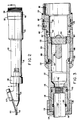
- the adapter 118 is constructed from a generally cylindrical hollow body 132 having a threaded end 134.
- a cylindrical hollow seal nut 136 is frictionally retained within the threaded end 134 of the body 132 by means of a threaded clamp nut 138.
- the clamp nut 138 is provided with a central opening 140 through which one end of the fiberscope 114 passes into the hollow interior of the seal nut 136.
- the fiberscope 114 is retained within the seal nut 136 by means of it having a threaded end 142 for engagement with a threaded portion of the seal nut.
- a watertight seal is formed between the fiberscope 114 and the seal nut 136 by means of O-ring 144. Likewise, a watertight seal is formed between the seal nut 136 and the body 132 of the fiberscope 118 by means of O-ring 146. As shown in Fig. 3, the image guide 116 extends through the fiberscope 114 and is arranged in alignment with the longitudinal axis of the adapter 118.
- elongated slotted openings 148 are circumferentially arranged and equally spaced about the body 132 of the adapter 118.
- An internally threaded hollow cylinder 150 is arranged concentrically overlying the slotted openings 148 and sealed to the body 132 by means of a pair of O-rings 152.
- a lens 154 having its transverse axis arranged in alignment with the longitudinal axis of the image guide 116 extending within the fiberscope 114 is movably arranged within the interior of the body 132.
- the lens 154 is movably retained by means of four circumferentially arranged threaded guides 156 having threaded ends 157 extending through the slotted openings 148 and into engagement with the threaded portion of the concentrically overlying cylinder 150.
- rotation of the cylinder 150 causes movement of the lens 154 along the longitudinal axis of the adapter 118 by means of the threaded guides 156.
- the image being transmitted by the image guide 116 may be focused and enlarged.
- the precise position of the lens 154 along the longitudinal axis of the adapter 118 may be retained by the set screws 158 extending through the cylinder 150 into engagement with the body 132 of the adapter.
- the right end of the adapter 118 is constructed to be eccentrically connected to the camera 110 such as Westinghouse ETV-1250 series cameras.
- the right end of the adapter 118 is provided with an opening 160 having its transverse axis arranged not in alignment with the transverse axis of the lens 154, as well as not in alignment with the longitudinal axis of the image guide 116 extending through the fiberscope 114.
- rotation of the adapter 118 about its longitudinal axis causes the image being transmitted by the image guide 116 to be rotated about a circular path.
- the image being transmitted by the image guide 116 may be centrally focused on the image receiving elements (not shown) contained within the camera 110 so as to overcome any misalignment between the lens 154 and the image receiving elements resulting from lack of precision in the construction of the mating parts of the adapter and camera.
- the adapter 118 is mounted to the camera 110 by means of a threaded cylindrical head connector 162.
- a watertight seal is provided at the connection of the head connector 162 and the camera 110 by means of an 0-ring 164.
- a watertight seal is provided between the head connector 162 and the body 132 of the adapter 118 by means of an O-ring 166.
- the head connector 162 is maintained on the right end of the adapter 118 by means of a head connector retaining ring 168 and set screws 170 extending through an opening therein and into engagement with the body 132 of the adapter.
- the adapter 118 provides an integral watertight connection between the fiberscope 114 and camera 110 for focusing and enlarging the image being transmitted by the image guide 116 to the image receiving elements within the camera.
- the system 100 being employed in a radiation environment, requires that the fiberoptic image guide 116, as well as the fiberoptic light guide 120 be constructed of materials to withstand radiation exposure while maintaining acceptable light transmission characteristics.
- the radiation resistant nature of the image guide 116 and light guide 120 permit their exposure to various dosages of radiation while retaining greater than about 50% light transmission.
- the core region of the image guide 116 and light guide 120 are manufactured from ultrapure silicon dioxide material i.e., having less than 5-10 parts per billion of impurities.
- the image guide 116 and light guide 120 made of such material can withstand a radiation flux of greater than about 10 4 rads per hour or an accumulated radiation dosage of greater than 10 4 rads.
- the lens 154 of the adapter 118 is also manufactured from ultrapure silicon dioxide material.
- the fiberoptic image guide 116 is constructed from a plurality of individual fibers arranged in a coherent bundle.
- coherent bundle is meant that the relative x-y position of one end of each fiber is at the same relative x-y position at its other end. In this manner, the relative x-y position of the image being transmitted by a fiber is maintained from one end to' the other.
- the coherent bundle of the image: guide 116 includes from 1,000 to 20,000 individual fibers each having a core diameter in the range of about 3 to 24 microns and an overall diameter in the range of from about 5 to 30 microns and having a numerical aperture of about 0.2, i.e., square root of the difference between the squares of the index of refraction of the core and cladding materials.
- the light guide 122 is not required to be manufactured of a coherent bundle of fibers.
- the image guide 120 can be manufactured from a single fiber having a core diameter of about 400 microns, however, multiple fibers can be used for transmission of a band of wavelengths of light, again made of ultrapure silicon dioxide material.
- FIG. 4a the image guide 116 and light guide 120 are each enclosed in a thin stainless steel tube 172, 174, respectively.
- the tube 174 of the light guide 120 is welded to the tube 172 of the image guide 116 to form an integral assembly having a transverse cross-section in a figure 8-shape.
- This cross-section allows the integral assembly of the image guide 116 and light guide 120 to be thin enough to pass -through very narrow channels formed between adjacent fuel elements 106, such as 0.070 inch channels, while providing optical capabilities that would normally require channel spacings that are at least twice as wide.
- a second light guide 120' having a thin stainless steel tube 174' is welded to the tube 172 of the image guide 116 to provide an integral assembly in which the light guides 120, 120' and image guide 116 are arranged lying in a common plane, i.e., wherein the guides in cross-section have their longitudinal axis arranged along a straight line.
- the integral assembly of the image guide 116 and light guide 120, 120' in accordance with the embodiment described can easily pass through the narrow channels formed between the fuel elements 106 within the radioactive nuclear fuel assembly 104. This embodiment is accordingly useful for illuminating both sides of the image guide 116.
- the free ends of the image guide 116 and light guide 120 are provided with a fixed focus lens 176 and a prism 178, for example, in a manner similar to that disclosed in U.S. Patent No. 3,856,000.
- the lens 176 and prism 178 combination with regard to the image guide 116, provides viewing at an angle to the longitudinal axis of the image guide. To this end, any viewing angle from 0 to 90 degrees may be employed, depending upon the specific prism used.
- the lens 176 and prism 178 combination permits focusing of light on the preselected portion of the tube 106 to be inspected within the radioactive nuclear fuel assembly 104.
- the free ends of the image guide 116 and light guide 120 may be provided with a forward oblique viewing angle as opposed to a lens 176 and prism 178 combination.
- the forward oblique viewing angle is provided as an elliptically polished face 180 at the free ends of the image guide 116 and light guide 120 and being arranged at an oblique angle to the longitudinal axis of the guides, e.g., 20-60 degrees.
- a preselected portion of a tube 106 may be effectively illuminated by the distal end of the light guide 120 and a focused image received by the distal end of the image guide 116 to be transmitted to the television camera 110 through the adapter 118.
- the selected portions of the tubes 106 of the fuel assembly 104 to be visually inspected are illuminated by the light guide 120 using the high intensity light source 122 such as helium/neon laser.
- the high intensity light source 122 such as helium/neon laser.
- any laser which emits any wave having a wavelength of from about 0.3 to 0.9 micrometers may be used.
- a suitable example is one such laser emitting a wavelength of 0.6238 micrometers.
- the system 100 can employ both visible and invisible light, i.e., infrared.
- the laser is connected to the light guide 120 by means of a connector 124 and fiberoptic guide 126.
- the laser can be arranged underwater in the spent fuel pool 102 or remote therefrom in the surrounding environment.
- a mercury arc lamp can be provided for direct illumination of the fuel elements 106 of the fuel assembly 104.
- the image of the preselected portion of the fuel element 106 is transmitted along the image guide 116 to the adapter 118.
- the lens 154 within the adapter 118 focuses and enlarges the image so as to impose the image over the entire surface of the image receiving elements within the camera 110, which camera is mounted to the three axis positioning device 108.
- the eccentrically mounted adapter 118 may be rotated about its longitudinal axis so as to align the center of the image being transmitted by the image guide 116 with the center of the image receiving elements within the camera 110.
- the camera 110 is constructed to be watertight and radiation resistant so as to enable the positioning of the camera as close as possible to the image being focused and enlarged by the lens 154 within the adapter 118 thereby minimizing transmission losses.
- a second camera 112 is similarly provided on the positioning device 108 so as to enable the visual monitoring of the location of the distal ends of the image guide 116 and light guide 120 with respect to the fuel elements 106. In this manner, the distal ends of the image guide 116 and light guide 120 may be monitored as the guides are inserted between the fuel elements 106 of the fuel assembly 104 while visually inspecting defects on preselected portions of the fuel elements by means of the camera 110 and remote monitor 128.
- the camera 112 is likewise constructed to be watertight and radiation resistant, for example, these cameras 110, 112 may be Westinghouse ETV-1250 series cameras.
- the positioning device 108 permits movement of the distal ends of the image guide 116 and light guide 120 along three mutually perpendicular axes, i.e., x, y and z axes of the fuel assembly 104.
- the camera 110 is mounted to a platform 182 and provided with a worm gear 184 for permitting controlled rotation of the camera about its longitudinal axis. Rotation of the camera 110 via the worm gear 184 causes like rotation of the distal ends of the image guide 116 and light guide 120 to facilitate viewing of predetermined portions of the fuel elements 106.
- the platform 182 is horizontally maintained by four rectangular spaced vertically extending rods 186 and slide blocks 187 mounted to the platform for sliding engagement with each of the rods.
- a vertically extending screw 188 is arranged between the rods 186 in threading engagement with a portion of the platform 182 and connected at one end to a motor 190. Rotation of the screw 188 by the motor 190 causes the platform 182 to be moved along the rods 186 in a vertical direction along the z axis of the positioning device 108 thereby causing similar movement of the camera 110 and distal ends of the image guide 116 and light guide 120.
- the second television camera 112 is mounted to a similar platform 192 overlying the first platform 182.
- the second camera 112 is pivotably mounted to the platform 192 via pin 193 at a location in alignment with the first camera 110.
- the camera 112 is pivotable along the z axis of the positioning device 108 such that the distal ends of the image guide 116 and light guide 120 may be monitored irrespective of their position with respect to the x, y and z axes of the fuel assembly 104.
- the lower ends of the rods 186 are secured to a platform 194 which is supported by an x-y positioning assembling 196.
- the positioning assembling 196 is in turn supported by a fixed platform 198 having suitable lifting rods 200 provided for raising and lowering the positioning device 108 into and out of the spent fuel pool 102.
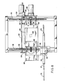
- the x-y positioning assembling 196 is shown in detail in Fig. 8. Referring specifically to Fig. 8, the platform 194 is supported by a pair of parallel spaced rods 202 by means of a slide block (not shown) similar to slide blocks 187 and attached to the underside of each corner of the platform.
- a screw 204 is positioned midway between the rods 202 and engaging a portion of the underside of the platform by means of threaded block 206.
- One end of the screw 204 is coupled to a motor 208 through a gear box assembly 210 and drive belt (not shown) engaging gears 212, 214 provided on the motor and gear box assembly.
- Rotation of the motor 208 causes rotation of the screw 204 and ultimately traverses the platform 194 along the rods 202 and along the y axis of the positioning device 108.
- a pair of parallel spaced apart gear tracks 216 are arranged underlying the platform 194 in a transverse direction to the rods 202.
- a pair of gears 218 are connected to a shaft 220, which shaft has one end connected to a motor 222. The gears 218 are arranged in engagement with the gear tracks 216.
- the rods 202 and shaft 220 are commonly supported at their opposite ends between a pair of side frames 224.
- rotation of the motor 222 causes the gears 218 to rotate in engagement along the gear tracks 216, thereby moving the platform 194 along the x axis of the positioning device 108.
- the positioning device 108 is suitably adapted for positioning the ends of the image guide 116 and light guide 120 at a predetermined location along the three mutually perpendicular axes of the fuel assembly 104.
- the three axes positioning device 108 is lowered into the spent fuel pool 102 adjacent the radioactive nuclear fuel assembly 104 by means of the lifting rods 200.
- the distal ends of the image guide 116 and light guide 120 can be positioned interiorly within the fuel assembly 104 for visual inspection of a predetermined portion of the fuel elements 106 by means of the positioning device 108.
- Rotation of the motor 190 effect displacement of the-ends--of the image guide 116 and light guide 120 along the z axis of the fuel assembly 104
- rotation of the motor 208 will cause displacement of the ends of the guides along the y axis of the fuel assembly
- rotation of the motor 222 will cause displacement of the distal ends of the guides along the .x axis of the fuel assembly.
- the respective position of the ends of the image guide 116 and light guide 120 may be continuously monitored by means of the closed circuit television camera 112.
- the image guide 116 and light guide 120 may be rotated about their axes by means of the worm gear 184 connected to the closed circuit television camera 110, which camera receives the images of those portions of the fuel elements 106 being inspected using the remote monitor 128.
- the fuel elements 106 are illuminated by the high intensity light source 122 such as a laser coupled to the light guide 120 or use of, for example, a mercury arc lamp.
- the system is constructed of a fiberoptic image guide having a core of silicon dioxide material for transmitting an image of preselected portions of the fuel elements of the fuel assembly, the image guide includes a plurality of individual fibers arranged in a coherent bundle, a light source for emitting light, transmitting means for transmitting the light emitted from the light source to illuminate the preselected portions of the fuel elements, first receiving means arranged in the underwater environment for receiving the image transmitted by the image guide and for displaying the image at a position without the underwater environment and remote from the fiberoptic image guide, second receiving means arranged in the underwater environment for visually locating one end of the image ugide with respect lected portions of the fuel elements, and positioning means arranged in the underwater environment and supporting the first and second receiving means thereon, the positioning means positioning the ends of the image guide at a plurality of pres
Landscapes
- Physics & Mathematics (AREA)
- Engineering & Computer Science (AREA)
- Plasma & Fusion (AREA)
- General Engineering & Computer Science (AREA)
- High Energy & Nuclear Physics (AREA)
- Astronomy & Astrophysics (AREA)
- General Physics & Mathematics (AREA)
- Optics & Photonics (AREA)
- Monitoring And Testing Of Nuclear Reactors (AREA)
- Instruments For Viewing The Inside Of Hollow Bodies (AREA)
- Measurement Of Radiation (AREA)
Applications Claiming Priority (2)
| Application Number | Priority Date | Filing Date | Title |
|---|---|---|---|
| US06/542,612 US4764334A (en) | 1983-10-17 | 1983-10-17 | Visual inspection system for radioactive fuel assemblies using fiberoptics |
| US542612 | 1990-06-25 |
Publications (2)
| Publication Number | Publication Date |
|---|---|
| EP0138607A2 true EP0138607A2 (fr) | 1985-04-24 |
| EP0138607A3 EP0138607A3 (fr) | 1987-09-09 |
Family
ID=24164571
Family Applications (1)
| Application Number | Title | Priority Date | Filing Date |
|---|---|---|---|
| EP84307050A Withdrawn EP0138607A3 (fr) | 1983-10-17 | 1984-10-15 | Système de l'inspection visuelle fibre-optique des assemblages combustibles radioactifs |
Country Status (5)
| Country | Link |
|---|---|
| US (1) | US4764334A (fr) |
| EP (1) | EP0138607A3 (fr) |
| JP (1) | JPS60102608A (fr) |
| KR (1) | KR850003279A (fr) |
| ES (1) | ES8605122A1 (fr) |
Cited By (3)
| Publication number | Priority date | Publication date | Assignee | Title |
|---|---|---|---|---|
| GB2205968A (en) * | 1987-06-15 | 1988-12-21 | Edward Loughran | Remote viewing optical fibre cable systems |
| US4854302A (en) * | 1987-11-12 | 1989-08-08 | Welch Allyn, Inc. | Video equipped endoscope with needle probe |
| EP0686860A3 (fr) * | 1994-06-07 | 1997-02-26 | Kawasaki Heavy Ind Ltd | Dispositif d'inspection d'un four |
Families Citing this family (18)
| Publication number | Priority date | Publication date | Assignee | Title |
|---|---|---|---|---|
| JPS60154225A (ja) * | 1984-01-24 | 1985-08-13 | Dainichi Nippon Cables Ltd | フアイバ−スコ−プ |
| JPS61292121A (ja) * | 1985-06-18 | 1986-12-22 | Mitsubishi Cable Ind Ltd | フアイバ−スコ−プ |
| US5016151A (en) * | 1989-05-17 | 1991-05-14 | Hydroimage | High-intensity underwater light source |
| JPH0324623U (fr) * | 1989-07-21 | 1991-03-14 | ||
| JPH03125110A (ja) * | 1989-10-09 | 1991-05-28 | Mitsubishi Cable Ind Ltd | ファイバスコープ及びその使用方法 |
| US5916210A (en) * | 1990-01-26 | 1999-06-29 | Intraluminal Therapeutics, Inc. | Catheter for laser treatment of atherosclerotic plaque and other tissue abnormalities |
| JP2656380B2 (ja) * | 1990-11-05 | 1997-09-24 | 株式会社東芝 | 異物回収装置 |
| DE69115307T2 (de) * | 1990-03-05 | 1996-06-13 | Toshiba Kawasaki Kk | Einrichtung für das Entfernen von Fremdkörpern für ein Kernkraftwerksbrennelement |
| US5235855A (en) * | 1991-03-25 | 1993-08-17 | Westinghouse Electric Corp. | Rod positioning apparatus |
| EP0625266B1 (fr) * | 1992-02-07 | 1999-05-06 | WINSTON, Thomas R. | Procede et dispositif d'inspection ultrasonore de zones inaccessibles |
| US5265129A (en) * | 1992-04-08 | 1993-11-23 | R. Brooks Associates, Inc. | Support plate inspection device |
| US5305356B1 (en) * | 1992-05-14 | 1998-09-01 | Brooks Support Systems Inc | Inspection device |
| WO1995022283A1 (fr) * | 1992-10-26 | 1995-08-24 | Ultrasonic Sensing & Monitoring Systems, Inc. | Catheter utilisant des fibres optiques pour transmettre l'energie laser et ultrasonore |
| US5347551A (en) * | 1993-07-09 | 1994-09-13 | General Electric Company | Method for examining irradiated fuel bundle spacer springs using fiber-optic visual inspection equipment |
| KR100268048B1 (ko) * | 1996-10-28 | 2000-11-01 | 고바야시 마사키 | 수중레이저영상장치 |
| DE19905970A1 (de) * | 1999-02-12 | 2000-08-31 | Siemens Ag | Miniaturendoskop und Verfahren zur Inspektion von Brennelementen |
| US7106359B2 (en) * | 2000-05-31 | 2006-09-12 | Fantone Stephen J | Subsurface video observation system |
| DE102009028793B3 (de) * | 2009-07-20 | 2011-01-27 | Areva Np Gmbh | Verfahren und Vorrichtung zum Ermitteln der Verformung eines Brennelementes eines Druckwasserreaktors |
Family Cites Families (20)
| Publication number | Priority date | Publication date | Assignee | Title |
|---|---|---|---|---|
| US3265584A (en) * | 1963-11-13 | 1966-08-09 | Richard C Cooper | Nuclear reactor viewing system |
| US3434775A (en) * | 1965-04-23 | 1969-03-25 | Iota Cam Corp | Flexible fiber optic borescope |
| US3724922A (en) * | 1970-12-17 | 1973-04-03 | I Jones | Scope for viewing the internal surface of a bore of similar cavity |
| US3710091A (en) * | 1971-01-27 | 1973-01-09 | J Holcomb | Fiber optic illuminator apparatus for scientific instruments |
| JPS4932484U (fr) * | 1972-06-19 | 1974-03-20 | ||
| FR2298859A1 (fr) * | 1975-01-22 | 1976-08-20 | Framatome Sa | Appareil et installation d'examen des barreaux combustibles d'un reacteur nucleaire |
| US4313791A (en) * | 1977-05-06 | 1982-02-02 | The Babcock & Wilcox Company | Method for locating defective nuclear fuel elements |
| US4174255A (en) * | 1977-05-06 | 1979-11-13 | The Babcock & Wilcox Company | Apparatus for locating defective nuclear fuel elements |
| SE439377B (sv) * | 1978-07-26 | 1985-06-10 | Hitachi Ltd | Anordning for optisk inspektion av rorledningar |
| JPS5518962A (en) * | 1978-07-27 | 1980-02-09 | Hitachi Ltd | Device for detecting in nuclear reactor vessel |
| US4253447A (en) * | 1978-10-16 | 1981-03-03 | Welch Allyn, Inc. | Color endoscope with charge coupled device and television viewing |
| US4229069A (en) * | 1978-11-30 | 1980-10-21 | Motin Jury D | Device for remote viewing of objects in ionizing radiation fields |
| JPS5586436A (en) * | 1978-12-22 | 1980-06-30 | Olympus Optical Co | Endoscope |
| US4281929A (en) * | 1979-05-17 | 1981-08-04 | The United States Of America As Represented By The United States Department Of Energy | Small diameter, deep bore optical inspection system |
| JPS5619020A (en) * | 1979-07-26 | 1981-02-23 | Fuji Photo Optical Co Ltd | Endscope optical system |
| AU532512B2 (en) * | 1979-09-07 | 1983-10-06 | Upjohn and Horton | Anti-allergenic compounds for bone mineral resorption |
| FR2494837A1 (fr) * | 1980-11-26 | 1982-05-28 | Commissariat Energie Atomique | Dispositif de controle des dimensions et de l'ecartement de pieces rigides disposees en faisceau |
| JPS57168195A (en) * | 1981-04-08 | 1982-10-16 | Mitsubishi Electric Corp | Reactor inspection device |
| US4432931A (en) * | 1981-10-02 | 1984-02-21 | Electric Power Research Institute, Inc. | Inspection system |
| JPS60154225A (ja) * | 1984-01-24 | 1985-08-13 | Dainichi Nippon Cables Ltd | フアイバ−スコ−プ |
-
1983
- 1983-10-17 US US06/542,612 patent/US4764334A/en not_active Expired - Lifetime
-
1984
- 1984-10-11 ES ES536735A patent/ES8605122A1/es not_active Expired
- 1984-10-13 KR KR1019840006353A patent/KR850003279A/ko not_active Withdrawn
- 1984-10-15 EP EP84307050A patent/EP0138607A3/fr not_active Withdrawn
- 1984-10-17 JP JP59216484A patent/JPS60102608A/ja active Pending
Cited By (3)
| Publication number | Priority date | Publication date | Assignee | Title |
|---|---|---|---|---|
| GB2205968A (en) * | 1987-06-15 | 1988-12-21 | Edward Loughran | Remote viewing optical fibre cable systems |
| US4854302A (en) * | 1987-11-12 | 1989-08-08 | Welch Allyn, Inc. | Video equipped endoscope with needle probe |
| EP0686860A3 (fr) * | 1994-06-07 | 1997-02-26 | Kawasaki Heavy Ind Ltd | Dispositif d'inspection d'un four |
Also Published As
| Publication number | Publication date |
|---|---|
| US4764334A (en) | 1988-08-16 |
| JPS60102608A (ja) | 1985-06-06 |
| EP0138607A3 (fr) | 1987-09-09 |
| ES536735A0 (es) | 1986-03-01 |
| ES8605122A1 (es) | 1986-03-01 |
| KR850003279A (ko) | 1985-06-13 |
Similar Documents
| Publication | Publication Date | Title |
|---|---|---|
| US4764334A (en) | Visual inspection system for radioactive fuel assemblies using fiberoptics | |
| JP2799291B2 (ja) | 炉内検査装置 | |
| US4741878A (en) | Process and device for inspecting control rod clusters for nuclear fuel assemblies | |
| US4815816A (en) | Image transportation device using incoherent fiber optics bundles and method of using same | |
| US8274735B2 (en) | Analytical laser ablation of solid samples for ICP, ICP-MS, and FAG-MS analysis | |
| US4518843A (en) | Laser lens and light assembly | |
| CA1247360A (fr) | Methode et dispositif de controle optique de la forme et des dimensions d'extremites de tubes dans un generateur de vapeur | |
| US4509104A (en) | High temperature resistant lighting device | |
| JP4030693B2 (ja) | 特に隠れたはんだ接合部の外観検査装置及び外観検査方法 | |
| US4635111A (en) | Optical fiber inspection system | |
| US5544206A (en) | Reactor head work station | |
| US20020071513A1 (en) | Miniature endoscope and method for the inspection of fuel elements | |
| EP3527974B1 (fr) | Dispositifs d'inspection et procédés d'inspection d'une fente | |
| US5347551A (en) | Method for examining irradiated fuel bundle spacer springs using fiber-optic visual inspection equipment | |
| JPS59166838A (ja) | 光フアイバ−の屈折率を測定する装置 | |
| RU2483337C2 (ru) | Оптико-телевизионное устройство для дистанционного визуального контроля | |
| RU2480799C2 (ru) | Оптико-телевизионное устройство для дистанционного визуального контроля и измерения линейных размеров | |
| KR101857106B1 (ko) | 칼란드리아 내부 구조물 검사장치 | |
| US6646734B1 (en) | Method and an arrangement for inspection of and measuring at an object | |
| JPS62108219A (ja) | 管内面検査装置 | |
| Swannack et al. | Design considerations, tooling, and equipment for remote in-service inspection of radioactive piping and pressure-vessel systems | |
| JPH0342418Y2 (fr) | ||
| Rochefort | CANDU in-reactor quantitative visual-based inspection techniques | |
| SU1335255A1 (ru) | Хирургическое смотровое устройство | |
| Ramsey | Novel spatial scanning method for tokamak spectroscopy |
Legal Events
| Date | Code | Title | Description |
|---|---|---|---|
| PUAI | Public reference made under article 153(3) epc to a published international application that has entered the european phase |
Free format text: ORIGINAL CODE: 0009012 |
|
| AK | Designated contracting states |
Designated state(s): BE FR GB IT SE |
|
| PUAL | Search report despatched |
Free format text: ORIGINAL CODE: 0009013 |
|
| AK | Designated contracting states |
Kind code of ref document: A3 Designated state(s): BE FR GB IT SE |
|
| 17P | Request for examination filed |
Effective date: 19880303 |
|
| STAA | Information on the status of an ep patent application or granted ep patent |
Free format text: STATUS: THE APPLICATION IS DEEMED TO BE WITHDRAWN |
|
| 18D | Application deemed to be withdrawn |
Effective date: 19900501 |
|
| RIN1 | Information on inventor provided before grant (corrected) |
Inventor name: KING, WILLIAM EARL Inventor name: HEALY, LAWRENCE GEORGE |