EP0138700A1 - Verbinder für isolierte elektrische Kabel - Google Patents
Verbinder für isolierte elektrische Kabel Download PDFInfo
- Publication number
- EP0138700A1 EP0138700A1 EP84402009A EP84402009A EP0138700A1 EP 0138700 A1 EP0138700 A1 EP 0138700A1 EP 84402009 A EP84402009 A EP 84402009A EP 84402009 A EP84402009 A EP 84402009A EP 0138700 A1 EP0138700 A1 EP 0138700A1
- Authority
- EP
- European Patent Office
- Prior art keywords
- skirt
- sleeve
- connector
- cables
- crimping
- Prior art date
- Legal status (The legal status is an assumption and is not a legal conclusion. Google has not performed a legal analysis and makes no representation as to the accuracy of the status listed.)
- Granted
Links
Images

Classifications
-
- H—ELECTRICITY
- H01—ELECTRIC ELEMENTS
- H01R—ELECTRICALLY-CONDUCTIVE CONNECTIONS; STRUCTURAL ASSOCIATIONS OF A PLURALITY OF MUTUALLY-INSULATED ELECTRICAL CONNECTING ELEMENTS; COUPLING DEVICES; CURRENT COLLECTORS
- H01R4/00—Electrically-conductive connections between two or more conductive members in direct contact, i.e. touching one another; Means for effecting or maintaining such contact; Electrically-conductive connections having two or more spaced connecting locations for conductors and using contact members penetrating insulation
- H01R4/10—Electrically-conductive connections between two or more conductive members in direct contact, i.e. touching one another; Means for effecting or maintaining such contact; Electrically-conductive connections having two or more spaced connecting locations for conductors and using contact members penetrating insulation effected solely by twisting, wrapping, bending, crimping, or other permanent deformation
- H01R4/18—Electrically-conductive connections between two or more conductive members in direct contact, i.e. touching one another; Means for effecting or maintaining such contact; Electrically-conductive connections having two or more spaced connecting locations for conductors and using contact members penetrating insulation effected solely by twisting, wrapping, bending, crimping, or other permanent deformation by crimping
- H01R4/20—Electrically-conductive connections between two or more conductive members in direct contact, i.e. touching one another; Means for effecting or maintaining such contact; Electrically-conductive connections having two or more spaced connecting locations for conductors and using contact members penetrating insulation effected solely by twisting, wrapping, bending, crimping, or other permanent deformation by crimping using a crimping sleeve
- H01R4/203—Electrically-conductive connections between two or more conductive members in direct contact, i.e. touching one another; Means for effecting or maintaining such contact; Electrically-conductive connections having two or more spaced connecting locations for conductors and using contact members penetrating insulation effected solely by twisting, wrapping, bending, crimping, or other permanent deformation by crimping using a crimping sleeve having an uneven wire-receiving surface to improve the contact
-
- H—ELECTRICITY
- H01—ELECTRIC ELEMENTS
- H01R—ELECTRICALLY-CONDUCTIVE CONNECTIONS; STRUCTURAL ASSOCIATIONS OF A PLURALITY OF MUTUALLY-INSULATED ELECTRICAL CONNECTING ELEMENTS; COUPLING DEVICES; CURRENT COLLECTORS
- H01R4/00—Electrically-conductive connections between two or more conductive members in direct contact, i.e. touching one another; Means for effecting or maintaining such contact; Electrically-conductive connections having two or more spaced connecting locations for conductors and using contact members penetrating insulation
- H01R4/10—Electrically-conductive connections between two or more conductive members in direct contact, i.e. touching one another; Means for effecting or maintaining such contact; Electrically-conductive connections having two or more spaced connecting locations for conductors and using contact members penetrating insulation effected solely by twisting, wrapping, bending, crimping, or other permanent deformation
- H01R4/18—Electrically-conductive connections between two or more conductive members in direct contact, i.e. touching one another; Means for effecting or maintaining such contact; Electrically-conductive connections having two or more spaced connecting locations for conductors and using contact members penetrating insulation effected solely by twisting, wrapping, bending, crimping, or other permanent deformation by crimping
- H01R4/20—Electrically-conductive connections between two or more conductive members in direct contact, i.e. touching one another; Means for effecting or maintaining such contact; Electrically-conductive connections having two or more spaced connecting locations for conductors and using contact members penetrating insulation effected solely by twisting, wrapping, bending, crimping, or other permanent deformation by crimping using a crimping sleeve
-
- H—ELECTRICITY
- H01—ELECTRIC ELEMENTS
- H01R—ELECTRICALLY-CONDUCTIVE CONNECTIONS; STRUCTURAL ASSOCIATIONS OF A PLURALITY OF MUTUALLY-INSULATED ELECTRICAL CONNECTING ELEMENTS; COUPLING DEVICES; CURRENT COLLECTORS
- H01R4/00—Electrically-conductive connections between two or more conductive members in direct contact, i.e. touching one another; Means for effecting or maintaining such contact; Electrically-conductive connections having two or more spaced connecting locations for conductors and using contact members penetrating insulation
- H01R4/58—Electrically-conductive connections between two or more conductive members in direct contact, i.e. touching one another; Means for effecting or maintaining such contact; Electrically-conductive connections having two or more spaced connecting locations for conductors and using contact members penetrating insulation characterised by the form or material of the contacting members
- H01R4/62—Connections between conductors of different materials; Connections between or with aluminium or steel-core aluminium conductors
-
- H—ELECTRICITY
- H01—ELECTRIC ELEMENTS
- H01R—ELECTRICALLY-CONDUCTIVE CONNECTIONS; STRUCTURAL ASSOCIATIONS OF A PLURALITY OF MUTUALLY-INSULATED ELECTRICAL CONNECTING ELEMENTS; COUPLING DEVICES; CURRENT COLLECTORS
- H01R4/00—Electrically-conductive connections between two or more conductive members in direct contact, i.e. touching one another; Means for effecting or maintaining such contact; Electrically-conductive connections having two or more spaced connecting locations for conductors and using contact members penetrating insulation
- H01R4/70—Insulation of connections
Definitions
- the present invention relates to a connector for insulated electrical cables, and more particularly a connector of the type comprising a conductive sleeve having two opposite housings for the stripped ends of two cables to be connected, an insulating skirt surrounding the sleeve and seals interposed between the skirt and the ends of the cable insulation sheaths, the mechanical connection between the connector and the stripped ends of the cables having to be carried out by crimping the connector on the ends of the cables.
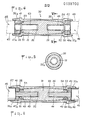
- FIG. 1 illustrates such a known connector; the right part shows the connector before crimping, with the sleeve 1, the skirt 2 and the seal 3; the left side shows the connector after crimping, the sleeve 1 being crimped on the stripped end of the cable while the seal is compressed between the cable insulation sheath and the skirt as a result of the elongation of the sleeve.
- the dielectric tightness produced by the seal 3 after crimping is not always satisfactory. Indeed, for the same joint, this tightness depends on the shape of the cable sheath, shape which varies according to the manufacturers. In addition, in the case of polyphase lines, the identification of the phases is sometimes carried out by marks in relief on the sheaths of the cables, which prevents obtaining a good dielectric tightness.
- the object of the present invention is to remedy this drawback by proposing a connector by which good dielectric tightness is obtained independently of possible variations in the shape of the outer sheath of the cables to be connected.
- the dielectric tightness obtained is made independent of possible variations or irregularities in the shape of the cable insulation sheath.
- the skirt is made of a synthetic material whose elongation coefficient is greater than that of the material forming the sleeve.
- the outer surface of the sleeve and the corresponding inner surface of the skirt have a diameter which varies between the middle of the connector and each end of the latter. Thanks to this shape, for example in “barrel” or biconical, components of axial forces are generated during crimping and allow the desired differential elongation to be obtained without the need for several crimping passes.
- the sleeve has at least one notch cooperating with a part of the skirt projecting inside thereof, so that the crimping causes the projection of this projecting part out of the 'notch and its abutment at the end of the sleeve, thus preventing the return of the projecting part in the notch after crimping.
- This arrangement also contributes to ensuring the differential elongation necessary for good compression of the seals.
- the connector 10 illustrated in FIG. 2 comprises a metallic sleeve 11, conductive of electricity, a skirt 15 of insulating synthetic material and two seals 21, 22 also made of an insulating synthetic material.
- the cylindrical sleeve 11 comprises two opposite housings 12, 13 opening on its end faces and intended to receive the stripped ends 23, 24 of the cables to be connected 25, 26 (shown in dashed lines in FIG. 2).
- the skirt 15 is in two parts 16, 17 placed on the sleeve 11 from the two ends of the latter and joined in the central part of the connector by overmolding of a connecting piece 20 of a material similar to that of parts 16 and 17.
- the part 20 has a central part molded on a flange 14 of the sleeve 11 and two lateral annular parts penetrating into grooves formed in the parts 16, 17 in the vicinity of their adjacent ends.
- the skirt 15 has end portions 16a, 17a of greater thickness, the internal diameter of which corresponds substantially to the external diameter of the insulation sheaths 27, 28 of the cables 25, 26.
- Internal flanges 18, 19 integral with the skirt 15 are formed substantially at the connections of the end portions 16a, 17a with the rest of the skirt 15; they limit the engagement of the skirt parts 16, 17 on the sleeve 11 coming into contact with the ends of the sleeve and have an internal diameter greater than that of the stripped part of the cables.
- the seals 21, 22 are housed in the end portions 16a, 17a of the skirt 15. They are for example made of synthetic rubber and have a cross section substantially equal to that of the insulation sheaths 27, 28 of the cables 25, 26. It is however possible to give the seals 21, 22 an outside diameter slightly greater than the inside diameter of the end portions 16a, 17a so that the seals 21, 22 can be immobilized permanently at the ends of the skirt 15.
- the cables 25, 26 are connected as follows.
- the stripped ends 23, 24 of the cables 25, 26 are introduced into the housings 12, 13 through the seals 21, 22 until the end faces 27a, 28a of the insulation sheaths 27, 28 come into contact with the seals 21, 22, applying these against the flanges 18, 19.
- the connector 10 is crimped on each end of the cable.
- the sleeve 11 is successively tightened on one and the other stripped end, ensuring the mechanical and electrical connection between the cables 25, 26.
- the parts of the skirts 16, 17 lengthen, compressing the seals 21, 22.
- a material having a coefficient of elongation greater than that of the material constituting the sleeve 11 is chosen for the skirt parts 16, 17.
- the skirt parts 16, 17 an injectable plastic material such as a polyamide, the sleeve 11 being made of an aluminum alloy such as that known under the name A5. This difference in elongation coefficient results, after crimping, in clearances 29 between the ends of the sleeve 11 and the flanges 18, 19.
- Obtaining sufficient differential elongation to ensure the desired compression of the seals 21, 22 may require a relatively long shrinking zone, the shrinking may require several crimping passes.
- a connector as shown in FIGS. 4 and 5 will advantageously be used.
- Figures 4 and 5 show the connector 30 before crimping. It includes a metal sleeve 31, a skirt 35 and two seals 41, 42.
- the sleeve 31 has a barrel, or biconical, shape with a decreasing outside diameter from the middle of the sleeve to each end of the latter. At these ends, the sleeve 31 has two cylindrical housings 32, 33 intended to receive the stripped ends 43, 44 of cables to be connected 45, 46 (shown in dashes in FIG. 4).
- the skirt 35 is obtained by overmolding. It has an internal surface which adapts to the external surface of the sleeve 31, which gives it an increasing thickness from the middle of the sleeve in the direction of each end.
- the end parts 36a, 37a of the skirt 35 have internal flanges 38, 39 similar to those 18, 19 of the end parts of the skirt 15 of FIG. 2 but are distinguished from the latter by the additional presence of circular lips 51, 52 protruding inside the skirt 35.
- Each lip 51, 52 is housed in a notch or peripheral groove 53, 54 of corresponding shape formed at the end of the sleeve 31.
- the seals 41, 42 are housed in the end parts 36a, 37a of the skirt 35.
- the materials constituting the elements of the connector 30 may be identical to those of the corresponding elements of connector 10 described above.
- the connector is crimped on each end of the cable.
- the crimping generates components of axial forces which promote elongation. This is why a single crimping pass may suffice to obtain the desired differential elongation. It is therefore not necessary to have a shrinking zone as long as that which must be provided to allow several crimping passes.
- one of the important advantages of the embodiment of Figures 4 to 6 consists in the fact that the metal sleeve 31 can be relatively short. As an indication, for the same section of cable, the length of the sleeve 31 can be 50% to 60% less than that of the sleeve 11 of FIG. 2.
- asperities or internal toothing such as 33a (FIG. 5) are formed in the housings 32, 33.
- the connector according to the invention is applicable in principle to a wide range of cable cross-sections to be connected, for example from 4 mm 2 to 95 mm 2 .
Landscapes
- Insulated Conductors (AREA)
- Connector Housings Or Holding Contact Members (AREA)
- Connections Effected By Soldering, Adhesion, Or Permanent Deformation (AREA)
- Communication Cables (AREA)
- Coupling Device And Connection With Printed Circuit (AREA)
- Details Of Connecting Devices For Male And Female Coupling (AREA)
Priority Applications (1)
| Application Number | Priority Date | Filing Date | Title |
|---|---|---|---|
| AT84402009T ATE29804T1 (de) | 1983-10-14 | 1984-10-08 | Verbinder fuer isolierte elektrische kabel. |
Applications Claiming Priority (2)
| Application Number | Priority Date | Filing Date | Title |
|---|---|---|---|
| FR8316410 | 1983-10-14 | ||
| FR8316410A FR2553594B1 (fr) | 1983-10-14 | 1983-10-14 | Connecteur pour cables electriques isoles |
Publications (2)
| Publication Number | Publication Date |
|---|---|
| EP0138700A1 true EP0138700A1 (de) | 1985-04-24 |
| EP0138700B1 EP0138700B1 (de) | 1987-09-16 |
Family
ID=9293167
Family Applications (1)
| Application Number | Title | Priority Date | Filing Date |
|---|---|---|---|
| EP84402009A Expired EP0138700B1 (de) | 1983-10-14 | 1984-10-08 | Verbinder für isolierte elektrische Kabel |
Country Status (7)
| Country | Link |
|---|---|
| EP (1) | EP0138700B1 (de) |
| AT (1) | ATE29804T1 (de) |
| DE (1) | DE3466327D1 (de) |
| DK (1) | DK489484D0 (de) |
| ES (1) | ES291606Y (de) |
| FR (1) | FR2553594B1 (de) |
| PT (1) | PT79350B (de) |
Cited By (8)
| Publication number | Priority date | Publication date | Assignee | Title |
|---|---|---|---|---|
| GB2177131A (en) * | 1985-01-02 | 1987-01-14 | Polypipe Ltd | Drainage gulley |
| FR2629645A1 (fr) * | 1988-03-30 | 1989-10-06 | Capelles De La Fuente Rosa | Dispositif de connexion electrique pour la liaison de conducteurs isoles |
| WO1996003784A1 (de) * | 1994-07-28 | 1996-02-08 | Karl Pfisterer Elektrotechnische Spezialartikel Gmbh & Co. Kg | Presshülse |
| US5502280A (en) * | 1993-07-30 | 1996-03-26 | Etcon Corporation | Cable splice protector |
| GB2328087A (en) * | 1997-06-26 | 1999-02-10 | B & H Ltd | Connection for high voltage |
| GB2371420A (en) * | 2001-01-19 | 2002-07-24 | Yazaki Corp | Crimp connections |
| CN104701802A (zh) * | 2014-05-25 | 2015-06-10 | 安徽工程大学 | 用于电缆接头的压接环 |
| EP3062407B1 (de) * | 2015-02-27 | 2019-06-26 | Upeca | Anschlussmuffe zwischen leiterkabeln, herstellungsverfahren und einbauverfahren einer solchen muffe |
Families Citing this family (1)
| Publication number | Priority date | Publication date | Assignee | Title |
|---|---|---|---|---|
| DE102006028880A1 (de) | 2006-06-21 | 2007-12-27 | Yazaki Europe Ltd., Hemel Hempstead | Kabelverbindung |
Citations (3)
| Publication number | Priority date | Publication date | Assignee | Title |
|---|---|---|---|---|
| US3036147A (en) * | 1959-08-21 | 1962-05-22 | Fargo Mfg Co Inc | Connector |
| FR1533861A (fr) * | 1966-08-10 | 1968-07-19 | Amp Inc | Connecteur électrique |
| DE1615551A1 (de) * | 1963-03-21 | 1969-04-10 | Amp Inc | Gleichachsige elektrische Verbindungsklemme fuer gleichachsige elektrische Kabel |
-
1983
- 1983-10-14 FR FR8316410A patent/FR2553594B1/fr not_active Expired
-
1984
- 1984-10-08 DE DE8484402009T patent/DE3466327D1/de not_active Expired
- 1984-10-08 EP EP84402009A patent/EP0138700B1/de not_active Expired
- 1984-10-08 AT AT84402009T patent/ATE29804T1/de not_active IP Right Cessation
- 1984-10-11 ES ES1984291606U patent/ES291606Y/es not_active Expired
- 1984-10-12 PT PT79350A patent/PT79350B/pt not_active IP Right Cessation
- 1984-10-12 DK DK489484A patent/DK489484D0/da not_active Application Discontinuation
Patent Citations (3)
| Publication number | Priority date | Publication date | Assignee | Title |
|---|---|---|---|---|
| US3036147A (en) * | 1959-08-21 | 1962-05-22 | Fargo Mfg Co Inc | Connector |
| DE1615551A1 (de) * | 1963-03-21 | 1969-04-10 | Amp Inc | Gleichachsige elektrische Verbindungsklemme fuer gleichachsige elektrische Kabel |
| FR1533861A (fr) * | 1966-08-10 | 1968-07-19 | Amp Inc | Connecteur électrique |
Cited By (11)
| Publication number | Priority date | Publication date | Assignee | Title |
|---|---|---|---|---|
| GB2177131A (en) * | 1985-01-02 | 1987-01-14 | Polypipe Ltd | Drainage gulley |
| GB2177131B (en) * | 1985-01-02 | 1989-04-12 | Polypipe Ltd | A drainage gulley |
| FR2629645A1 (fr) * | 1988-03-30 | 1989-10-06 | Capelles De La Fuente Rosa | Dispositif de connexion electrique pour la liaison de conducteurs isoles |
| US5502280A (en) * | 1993-07-30 | 1996-03-26 | Etcon Corporation | Cable splice protector |
| WO1996003784A1 (de) * | 1994-07-28 | 1996-02-08 | Karl Pfisterer Elektrotechnische Spezialartikel Gmbh & Co. Kg | Presshülse |
| GB2328087A (en) * | 1997-06-26 | 1999-02-10 | B & H Ltd | Connection for high voltage |
| GB2371420A (en) * | 2001-01-19 | 2002-07-24 | Yazaki Corp | Crimp connections |
| GB2371420B (en) * | 2001-01-19 | 2003-03-19 | Yazaki Corp | Wire connecting structure and connecting method |
| US6734359B2 (en) | 2001-01-19 | 2004-05-11 | Yazaki Corporation | Wire connecting structure and connecting method |
| CN104701802A (zh) * | 2014-05-25 | 2015-06-10 | 安徽工程大学 | 用于电缆接头的压接环 |
| EP3062407B1 (de) * | 2015-02-27 | 2019-06-26 | Upeca | Anschlussmuffe zwischen leiterkabeln, herstellungsverfahren und einbauverfahren einer solchen muffe |
Also Published As
| Publication number | Publication date |
|---|---|
| PT79350B (fr) | 1986-07-22 |
| EP0138700B1 (de) | 1987-09-16 |
| PT79350A (fr) | 1984-11-01 |
| ATE29804T1 (de) | 1987-10-15 |
| ES291606Y (es) | 1987-01-16 |
| FR2553594A1 (fr) | 1985-04-19 |
| FR2553594B1 (fr) | 1986-02-21 |
| ES291606U (es) | 1986-05-01 |
| DK489484D0 (da) | 1984-10-12 |
| DE3466327D1 (en) | 1987-10-22 |
Similar Documents
| Publication | Publication Date | Title |
|---|---|---|
| FR2703191A1 (fr) | Connecteur pour câbles coaxiaux avec conducteur extérieur formé d'un tube ondulé. | |
| FR2730864A1 (fr) | Borne femelle electrique d'une seule piece | |
| EP0138700B1 (de) | Verbinder für isolierte elektrische Kabel | |
| LU82815A1 (fr) | Manchon pour proteger l'epissure de cables electriques ou telephoniques | |
| CH626754A5 (en) | Method for joining high-voltage cables and device for implementing this method | |
| EP0837543B1 (de) | Vorrichtung zur mechanischen und elektrischen Verbindung von zwei Teilbaugruppen eines Kraftfahrzeugwechselstromgenerators | |
| FR2844644A1 (fr) | Systeme d'etancheite pour connecteur electrique multibroche | |
| EP3561978B1 (de) | Isolator für ein kabelende | |
| EP0595708B1 (de) | Vorrichtung zum Verhindern des Schwindens der Isolation für kunststoffisolierte Energiekabel | |
| FR2579837A1 (fr) | Serre-cable pour installations electriques | |
| FR2667449A1 (fr) | Connecteur pour un cable coaxial blinde. | |
| WO2008145878A1 (fr) | Accessoire du type backshell pour connecteur | |
| FR2557390A1 (fr) | Cable de moyenne tension, isole par du papier, ferme | |
| WO2017029453A1 (fr) | Dispositif de connexion électrique amélioré | |
| FR2916089A1 (fr) | Connecteur pour cable coaxial a ame cylindrique creuse | |
| FR2633103A1 (fr) | Embout de cablage | |
| FR2686196A1 (fr) | Protection de terminaison de cable moyenne tension. | |
| EP4454084A1 (de) | Endverschluss für ein hochspannungs- oder höchstspannungsstromübertragungskabel und verfahren zur herstellung eines kabelendverschlusses | |
| FR3028677A1 (fr) | Assemblage d'un ensemble de raccordement electrique | |
| FR2634070A1 (fr) | Connecteur isole pour cables electriques | |
| EP3823120A1 (de) | Verbessertes elektrisches anschlusskit | |
| FR2655122A1 (fr) | Joint d'etancheite pour connecteur electrique, et connecteur qui en est equipe. | |
| CA1296400C (fr) | Cable electrique, notamment isole au papier impregne, a l'extremite duquel est rapporte un dispositif de raccordement | |
| FR2741484A1 (fr) | Piece de raccordement electrique | |
| EP0058580B1 (de) | Elektrischer Verbinder mit einfacher Verriegelung |
Legal Events
| Date | Code | Title | Description |
|---|---|---|---|
| PUAI | Public reference made under article 153(3) epc to a published international application that has entered the european phase |
Free format text: ORIGINAL CODE: 0009012 |
|
| AK | Designated contracting states |
Designated state(s): AT BE CH DE FR GB IT LI LU NL SE |
|
| 17P | Request for examination filed |
Effective date: 19850618 |
|
| 17Q | First examination report despatched |
Effective date: 19860128 |
|
| RAP1 | Party data changed (applicant data changed or rights of an application transferred) |
Owner name: CERAVER SOCIETE ANONYME DITE: |
|
| GRAA | (expected) grant |
Free format text: ORIGINAL CODE: 0009210 |
|
| AK | Designated contracting states |
Kind code of ref document: B1 Designated state(s): AT BE CH DE FR GB IT LI LU NL SE |
|
| REF | Corresponds to: |
Ref document number: 29804 Country of ref document: AT Date of ref document: 19871015 Kind code of ref document: T |
|
| REF | Corresponds to: |
Ref document number: 3466327 Country of ref document: DE Date of ref document: 19871022 |
|
| PG25 | Lapsed in a contracting state [announced via postgrant information from national office to epo] |
Ref country code: LU Free format text: LAPSE BECAUSE OF NON-PAYMENT OF DUE FEES Effective date: 19871031 |
|
| GBT | Gb: translation of ep patent filed (gb section 77(6)(a)/1977) | ||
| ITF | It: translation for a ep patent filed | ||
| PLBE | No opposition filed within time limit |
Free format text: ORIGINAL CODE: 0009261 |
|
| STAA | Information on the status of an ep patent application or granted ep patent |
Free format text: STATUS: NO OPPOSITION FILED WITHIN TIME LIMIT |
|
| 26N | No opposition filed | ||
| PGFP | Annual fee paid to national office [announced via postgrant information from national office to epo] |
Ref country code: CH Payment date: 19890814 Year of fee payment: 6 |
|
| PGFP | Annual fee paid to national office [announced via postgrant information from national office to epo] |
Ref country code: DE Payment date: 19890819 Year of fee payment: 6 |
|
| PGFP | Annual fee paid to national office [announced via postgrant information from national office to epo] |
Ref country code: SE Payment date: 19890822 Year of fee payment: 6 |
|
| PGFP | Annual fee paid to national office [announced via postgrant information from national office to epo] |
Ref country code: GB Payment date: 19890831 Year of fee payment: 6 |
|
| PGFP | Annual fee paid to national office [announced via postgrant information from national office to epo] |
Ref country code: BE Payment date: 19890907 Year of fee payment: 6 |
|
| PGFP | Annual fee paid to national office [announced via postgrant information from national office to epo] |
Ref country code: LU Payment date: 19890914 Year of fee payment: 6 |
|
| PGFP | Annual fee paid to national office [announced via postgrant information from national office to epo] |
Ref country code: FR Payment date: 19890925 Year of fee payment: 6 |
|
| PGFP | Annual fee paid to national office [announced via postgrant information from national office to epo] |
Ref country code: AT Payment date: 19891013 Year of fee payment: 6 |
|
| ITTA | It: last paid annual fee | ||
| PGFP | Annual fee paid to national office [announced via postgrant information from national office to epo] |
Ref country code: NL Payment date: 19891031 Year of fee payment: 6 |
|
| PG25 | Lapsed in a contracting state [announced via postgrant information from national office to epo] |
Ref country code: GB Effective date: 19901008 Ref country code: AT Effective date: 19901008 |
|
| PG25 | Lapsed in a contracting state [announced via postgrant information from national office to epo] |
Ref country code: SE Effective date: 19901009 |
|
| PG25 | Lapsed in a contracting state [announced via postgrant information from national office to epo] |
Ref country code: LI Effective date: 19901031 Ref country code: CH Effective date: 19901031 Ref country code: BE Effective date: 19901031 |
|
| BERE | Be: lapsed |
Owner name: CERAVER Effective date: 19901031 |
|
| PG25 | Lapsed in a contracting state [announced via postgrant information from national office to epo] |
Ref country code: NL Effective date: 19910501 |
|
| GBPC | Gb: european patent ceased through non-payment of renewal fee | ||
| NLV4 | Nl: lapsed or anulled due to non-payment of the annual fee | ||
| PG25 | Lapsed in a contracting state [announced via postgrant information from national office to epo] |
Ref country code: FR Effective date: 19910628 |
|
| REG | Reference to a national code |
Ref country code: CH Ref legal event code: PL |
|
| PG25 | Lapsed in a contracting state [announced via postgrant information from national office to epo] |
Ref country code: DE Effective date: 19910702 |
|
| REG | Reference to a national code |
Ref country code: FR Ref legal event code: ST |
|
| EUG | Se: european patent has lapsed |
Ref document number: 84402009.9 Effective date: 19910603 |