EP0138774A2 - Sprungmatte - Google Patents
Sprungmatte Download PDFInfo
- Publication number
- EP0138774A2 EP0138774A2 EP84810509A EP84810509A EP0138774A2 EP 0138774 A2 EP0138774 A2 EP 0138774A2 EP 84810509 A EP84810509 A EP 84810509A EP 84810509 A EP84810509 A EP 84810509A EP 0138774 A2 EP0138774 A2 EP 0138774A2
- Authority
- EP
- European Patent Office
- Prior art keywords
- mat
- frame
- jumping
- sections
- mat according
- Prior art date
- Legal status (The legal status is an assumption and is not a legal conclusion. Google has not performed a legal analysis and makes no representation as to the accuracy of the status listed.)
- Granted
Links
Images
Classifications
-
- A—HUMAN NECESSITIES
- A63—SPORTS; GAMES; AMUSEMENTS
- A63B—APPARATUS FOR PHYSICAL TRAINING, GYMNASTICS, SWIMMING, CLIMBING, OR FENCING; BALL GAMES; TRAINING EQUIPMENT
- A63B6/00—Mats or the like for absorbing shocks for jumping, gymnastics or the like
- A63B6/02—Mats or the like for absorbing shocks for jumping, gymnastics or the like for landing, e.g. for pole vaulting
-
- A—HUMAN NECESSITIES
- A63—SPORTS; GAMES; AMUSEMENTS
- A63B—APPARATUS FOR PHYSICAL TRAINING, GYMNASTICS, SWIMMING, CLIMBING, OR FENCING; BALL GAMES; TRAINING EQUIPMENT
- A63B2210/00—Space saving
- A63B2210/50—Size reducing arrangements for stowing or transport
Definitions
- the invention relates to a jumping mat for high and pole vault.
- Jump mats that are suitable for catching the athlete without injury after the jump are difficult to transport and store due to their dimensions when not in use. Therefore, in many cases, such mats remain in the place of their use for a longer period of time, even if they are in the open and therefore offer little or no protection against weather influences, abuse, vandalism and the like.
- Protective covers, such as grilles and the like only partially solve the problem and are also complex and expensive and in turn require a storage space when not in use.
- a transportable safety device for dangerous sports exercises is known from German Offenlegungsschrift 29 12 810, which consists of individual foam blocks that can be assembled into a large-area mat.
- the individual blocks are provided with incisions in the form of a grid from above through most of their thickness such that each block to a certain extent represents a bundle of foam columns.
- the transport and storage of the individual blocks are compared to a large, unseparated mat easier.
- assembling and disassembling a mat from blocks, which must be individually connected to one another by suitable connecting elements is cumbersome and time-consuming, so that even with this mat there is a tendency to leave it on site for a long time. This mat construction is therefore not a solution to the problem mentioned at the beginning.
- this mat is not a jumping mat, but a mat for gymnastics, floor exercises and the like, which naturally has completely different dimensions than a jumping mat.
- Handling and storage problems arise exclusively from the length of such mats, which can be up to 12 m. In order to reduce the longitudinal expansion for transport and storage, rolling up or zigzag folding is recommended. The relatively small thickness of such mats of 10 to a maximum of 100 mm does not prevent this type of handling.
- jumping mats are many times thicker, voluminous and heavier. and therefore more bulky.
- the solution described in DOS 27 51 815 to make handling and storage of the mats easier is therefore not suitable for jumping mats.
- the invention has for its object to provide a jumping mat, the handling of which is so facilitated that the risk of damage outside of its normal use is reduced.
- this object is achieved by means of a jumping mat made of two or more sections of essentially the same thickness and the same length, which are arranged parallel to one another and are connected to one another along one of the longitudinal edges touching each other in such a way that the sections by hinge around the edge connection are collapsible.
- a mat of this type is preferably arranged on a frame; which is also foldable by appropriate division and suitable hinge connections.
- This frame expediently has rollers or wheels for transport.
- a preferred embodiment of the mat is provided with a comparatively thinner protective mat covering the entire opened surface.
- the connection of the sections preferably consists of a lacing.
- a mat according to the invention consists e.g. essentially from two approximately equal parts 1,2 from a foam core, which is surrounded by a cover made of synthetic leather or the like.
- the cover for each mat part is in two parts.
- the two shell parts around each core are connected to one another in a manner known per se by means of a lacing guided by eyelets (FIG. 4).
- the two mat parts 1, 2 lie on a frame 3 such that their mutually facing longitudinal side surfaces 7, 8 touch.
- the whole mat top is with an additional protective mat 4 and possibly covered with a further cover (not shown).
- the two mat parts 1, 2 are connected to one another by a lacing 9 along the upper edges 5, 6 of the mutually facing side surfaces 7, 8.
- the lacing connection 9 is shown in Fig. 4 pulled apart for better visibility.
- the lacing is tightened to such an extent that the side surfaces 7, 8 and their upper edges 5, 6 touch.
- the lacing 9 forms a hinge, so to speak, about which the two mat parts 1, 2 can be turned or folded against one another. The folding happens so that a mat part 1 is fixed and the other mat part 2 is folded up and over the former (see FIG. 2).
- the frame 3 also consists of two parts 10; 11 which are hingedly connected to one another by hinges.
- One part 10 is provided with wheels 12 and serves as a chassis.
- this part 10 with the wheels 12 basically remains on the ground and is not opened.
- the mat part 1, which comes to rest on this frame part 10, can therefore be regarded as a fixed mat part.
- the other part 11 of the frame 3 is also folded up when the second mat part 2 is folded over.
- the entire structure is then roughly halved in its base area and is easier to find storage space than an open mat.
- the height of the structure, the twice the mat thickness plus the frame height is generally not a problem, as there is usually enough space available upwards.
- the sensitive mat surface is protected by folding it over.
- the frame has upwardly projecting brackets or plates 13, by means of which the mat is secured against slipping on the frame.
- the foldable part 11 of the frame 3 has no wheels but a support which at the same time has the function of preventing the frame from rolling away in the opened state.
- the protective mat 4 which seamlessly covers the opened mat, serves as spike protection when used as intended and at the same time as a cushion in the region of the lacing 9 of the two mat parts 1, 2.
- the invention is not limited to a two-part mat. Another division, which still allows the handling of a heavy jumping mat, is also conceivable. It would also make sense, for example, to split it into three parts with a central, fixed mat part and two folding parts arranged laterally in the form of wings.
- the connection of the mat parts to each other can also of course differently than by a lacing, for example by a so-called Velcro connection or the like.
Landscapes
- Health & Medical Sciences (AREA)
- General Health & Medical Sciences (AREA)
- Physical Education & Sports Medicine (AREA)
- Passenger Equipment (AREA)
- Mattresses And Other Support Structures For Chairs And Beds (AREA)
- Treatment Of Fiber Materials (AREA)
- Carpets (AREA)
Abstract
Description
- Die Erfindung betrifft eine Sprungmatte für Hoch- und Stabhochsprung.
- Sprungmatten, die geeignet sind, den Sportler nach dem Sprung verletzungsfrei aufzufangen, sind aufgrund ihrer Abmessungen schwierig zu transportieren und zu lagern, wenn sie nicht gebraucht werden. Deshalb verbleiben derartige Matten in vielen Fällen während längerer Zeit am Ort ihres Einsatzes, auch wenn dieser sich im Freien befindet und daher keinen oder nur geringen Schutz gegen Witterungseinflüsse, Missbrauch, Vandalismus und dergl. bietet. Schutzabdeckungen, wie Gitter und dergl. beseitigen das Problem nur teilweise und sind zudem aufwendig und teuer und benötigen ihrerseits einen Aufbewahrungsplatz während des Nichtgebrauchs.
- Aus der deutschen Offenlegungsschrift 29 12 810 ist eine transportabel Sicherheitseinrichtung für gefährliche Sportübungen bekannt, die aus einzelnen Schaumstoffblöcken besteht, die zu einer grossflächigen Matte zusammengesetzt werden können. Die individuellen Blöcke sind zur Erhöhung der Nachgiebigkeit und zur Verringerrung der Elastizität derart mit gitterförmig von oben durch den grössten Teil ihrer Dicke geführten Einschnitten versehen, dass jeder Block gewissermassen ein Bündel von Schaumstoffsäulen darstellt. Transport und Lagerung der einzelnen Blöcke sind im Vergleich zu einer grossen ungetrennten Matte einfacher. Auf der anderen Seite sind Auf- und Abbau einer Matte aus Blöcken, die zum Einsatz einzeln durch geeignete Verbindungselemente miteinander verbunden sein müssen, umständlich und zeitraubend, sodass auch bei dieser Matte die Tendenz besteht, sie über längere Zeit am Einsatzort zu belassen. Diese Mattenkonstruktion stellt also keine Lösung des eingangs erwähnten Problems dar.
- Aus der deutschen Offenlegungsschrift 27 51 815 ist eine elastische Matte für Sport und Gymnastikzwecke bekannt, deren Länge ein Mehrfaches ihrer Breite beträgt und die zum Transport und zur Lagerung platzsparend zusammenpackbar ist. Dies wird dadurch erreicht, dass die Matte in regelmässigen Abständen quer zu ihrer Längsrichtung verlaufende Einschnitte aufweist, die das Aufrollen oder Zusammenlegen erleichtern.
- Bei dieser Matte handelt es sich jedoch nicht um eine Sprungmatte, sondern eine Matte für Gymnastik, Bodenturnen und dergl., die naturgemäss völlig andere Abmessungen hat als eine Sprungmatte. Handhabungs- und Lagerungsprobleme ergeben sich ausschliesslich infolge der Länge derartiger Matten, die bis zu 12m betragen kann. Um für Transport und Lagerung die Längsausdehnung zu verringern, bietet sich ein Aufrollen oder zickzackförmiges Zusammenklappen an. Die verhältnismässige geringe Dicke derartiger Matten von 10 bis maximal 100 mm steht dieser Art der Handhabung nicht entgegen.
- Sprungmatten sind demgegenüber um ein Vielfaches dicker, voluminöser und schwerer.und demzufolge unhandlicher. Die in der DOS 27 51 815 beschriebene Lösung zur Erleichtung der Handhabung und Lagerung der Matten ist daher für Sprungmatten nicht geeignet.
- Der Erfindung liegt die Aufgabe zugrunde, eine Sprungmatte bereitzustellen, deren Handhabung so erleichtert ist, dass das Risiko ihrer Beschädigung ausserhalb ihres normalen Gebrauchs verringert ist.
- Erfindungsgemäss wird diese Aufgabe gelöst durch eine Sprungmatte, aus zwei oder mehr Teilstücken von im wesentlichen gleicher Dicke und gleicher Länge, die parallel nebeneinander angeordnet und jeweils entlang einer der einander berührenden Längskanten miteinander verbunden sind derart, dass die Teilstücke durch Drehung um die Kantenverbindung als Scharnier zusammenklappbar sind.
- Vorzugsweise ist eine Matte dieser Art auf einem Rahmen angeordnet; der durch entsprechende Aufteilung und geeignete Scharnierverbindungen ebenfalls klappbar ist. Zum Transport weist dieser Rahmen zweckmässigerweise Rollen- bzw. Räder auf. Eine bevorzugte Ausführungsform der Matte ist mit einer die ganze aufgeklappte Fläche überdeckenden vergleichsweise dünneren Schutzmatte versehen. Die Verbindung der Teilstücke besteht vorzugswe$ise in einer Verschnürung.
- Nachfolgend wird anhand der beiliegenden Zeichnungen ein bevorzugtes Ausführungsbeispiel der Erfindung beschrieben. Es zeigen
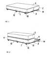
- Fig. 1 eine perspektivische Ansicht einer Matte im sprungbereiten, d.h. aufgeklappten Zustand mit Rahmen und Fahrwerk,
- Fig. 2 eine perspektivische Ansicht der in Fig. 1 gezeigten Matte mit zusammengeklappten Mattenteilen und noch offenem Rahmen,
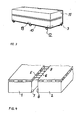
- Fig. 3 eine perspektivische Ansicht der vollständig zusammengeklappten Matte,
- Fig. 4 eine perspektivische Detailansicht der Verbindung der Mattenteile.
- Wie in Fig. 1 gezeigt, besteht eine Matte nach der Erfindung z.B. im wesentlichen aus zwei etwa gleich grossen Teilen 1,2 aus einem Schaumstoffkern, der von einer Hülle aus Kunstleder oder dergl. umgeben ist. Die Hülle für jeden Mattenteil ist zweiteilig. Die beiden Hüllenteile um jeden Kern sind mittels einer durch Oesen geführten Schnürung in an sich bekannter Weise miteinander verbunden (Fig. 4).
- Die beiden Mattenteile 1, 2 liegen so auf einem Rahmen 3, dass sich ihre einander zugewandeten Längsseitenflächen 7,8 berühren.
- Die ganze Mattenoberseite ist mit einer zusätzlichen Schutzmatte 4 und ggf. mit einer weiteren Hülle (nicht gezeigt) abgedeckt.
- Wie aus der detaillierten Fig.4 ferner ersichtlich, sind die beiden Mattenteile 1,2 entlang der oberen Kannten 5,6 der einander zugewandten Seitenflächen 7,8 durch eine Verschnürung 9 miteinander verbunden. Die Schnürverbindung 9 ist in Fig. 4 zwecks besserer Erkennbarkeit auseinandergezogen gezeigt. Im Benutzungszustand ist die Verschnürung aber soweit angezogen, dass sich die Seitenflächen 7,8 und deren obere Kanten 5,6 berühren. Die Verschnürung 9 bildet sozusagen ein Scharnier, um das die beiden Mattenteile 1,2 gegeneinander gedreht, bzw. geklappt werden können. Das Klappen geschieht so, dass ein Mattenteil 1 fest liegt und der andere Mattenteil 2 hoch und über den ersteren geklappt wird (vergl. Fig 2).
- Der Rahmen 3 besteht wie in Fig. 3 gezeigt, ebenfalls aus zwei Teilen 10; 11, die durch Scharniere klappbar miteinander verbunden sind. Der eine Teil 10 ist mit Rädern 12 versehen und dient als Fahrwerk. Zu diesem Zweck bleibt dieser Teil 10 mit den Rädern 12 grundsätzlich auf dem Boden stehen und wird nicht aufgeklappt. Der Mattenteil 1, der auf diesem Rahmenteil 10 zu liegen kommt, kann daher als festliegender Mattenteil angesehen werden.
- Der andere Teil 11 des Rahmens 3 wird, wenn der zweite Mattenteil 2 übergeklappt ist, ebenfalls hochgeklappt. Der gesamte Aufbau ist dann in seiner Grundfläche etwa halbiert und findet leichter einen Lagerplatz als eine offene Matte. Die Höhe des Aufbaus, die der doppelten Mattendicke plus der Rahmenhöhe entspricht, ist in der Regel kein Problem, da nach oben meist genügend Platz zur Verfügung steht. Ausserdem besteht ein Vorteil darin, dass die Hochlage der Unterseite des übergeklappten Mattenteils 2 ein unabsichtliches Betreten verhindert, was die Beschädigungsgefahr weiter reduziert. Schliesslich wird durch das Uebereinanderklappen vor allem die sensible Mattenoberfläche geschützt.
- An den Enden und den Seiten- und Stirnflächen weist der Rahmen nach oben ragende Bügel oder Platten 13 auf, durch die die Matte gegen Verrutschen auf dem Rahmen gesichert ist. Der klappbare Teil 11 des Rahmens 3 besitzt keine Räder sondern eine Stütze, die gleichzeitig die Funktion hat, den Rahmen im aufgeklappten Zustand am Wegrollen zu hindern.
- Die Schutzmatte 4, die die aufgeklappte Matte nahtlos abdeckt, dient bei der bestimmungsgemässen Benutzung als Spikesschutz und gleichzeitig als Polster im Bereich der Verschnürung 9 der beiden Mattenteile 1,2.
- Die Erfindung ist nicht auf eine zweiteilige Matte beschränkt. Auch eine andere Teilung, die das Handhaben einer schweren Sprungmatte noch zulässt, ist denkbar. Sie wäre z.B. eine Dreiteilung mit einem zentralen festliegenden Mattenteil und zwei seitlich flügelförmig angeordneten klappbaren Teilen ebenfalls sinnvoll. Auch die Verbindung der Mattenteile miteinander kann selbstverständlich anders als durch eine Verschnürung, beispielsweise durch eine sog. Klettverbindung oder dergl. erfolgen.
Claims (6)
- l. Sprungmatte für Hoch- und Stabhochsprung gekennzeichnet durch zwei oder mehr Teilstücke (1,2) von im wesentlichen gleicher Dicke und gleicher Länge, die parallel nebeneinander angeordnet und jeweils entlang einer der einander berührenden Längskanten (5,6) miteinander verbunden sind derart, dass die Teilstücke (1,2) durch Drehung um die Kantenverbindung (9) als Scharnier zusammenklappbar sind.
- 2. Sprungmatte nach Anspruch 1, dadurch gekennzeichnet, dass die Teilstücke (1,2) auf einem Rahmen (3) angeordnet sind, der durch entsprechende Aufteilung und Scharnierverbindung klappbar ist.
- 3. Sprungmatte nach Anspruch 2, dadurch gekennzeichnet, dass der Rahmen (3) Rollen bzw. Räder (12) aufweist.
- 4. Sprungmatte nach Anspruch 3, dadurch gekennzeichnet, dass die Rollen bzw. Räder (12) nur an einem Teil (10) des klappbaren Rahmens (3) angebracht sind.
- 5. Sprungmatte nach einem der Ansprüche 1-4, dadurch gekennzeichnet, dass sie mit einer die gesamte aufgeklappte Fläche überdeckende Schutzmatte (4) versehen ist.
- 6. Sprungmatte nach einem der Ansprüche 1-5, dadurch gekennzeichnet, dass die Verbindung der-Teilstücke (1,2) aus einer Verschnürung (9) besteht.
Priority Applications (1)
| Application Number | Priority Date | Filing Date | Title |
|---|---|---|---|
| AT84810509T ATE44347T1 (de) | 1983-10-19 | 1984-10-18 | Sprungmatte. |
Applications Claiming Priority (2)
| Application Number | Priority Date | Filing Date | Title |
|---|---|---|---|
| CH568683 | 1983-10-19 | ||
| CH5686/83 | 1983-10-19 |
Publications (3)
| Publication Number | Publication Date |
|---|---|
| EP0138774A2 true EP0138774A2 (de) | 1985-04-24 |
| EP0138774A3 EP0138774A3 (en) | 1986-04-02 |
| EP0138774B1 EP0138774B1 (de) | 1989-07-05 |
Family
ID=4297679
Family Applications (1)
| Application Number | Title | Priority Date | Filing Date |
|---|---|---|---|
| EP84810509A Expired EP0138774B1 (de) | 1983-10-19 | 1984-10-18 | Sprungmatte |
Country Status (3)
| Country | Link |
|---|---|
| EP (1) | EP0138774B1 (de) |
| AT (1) | ATE44347T1 (de) |
| DE (1) | DE3478843D1 (de) |
Cited By (7)
| Publication number | Priority date | Publication date | Assignee | Title |
|---|---|---|---|---|
| DE8804991U1 (de) * | 1988-04-15 | 1988-07-21 | Nucklies, Angelika, 6229 Walluf | Stabhochsprungtrainingskissen |
| AT390194B (de) * | 1986-01-03 | 1990-03-26 | Reinfrank Volker | Mit anderen matten verbindbare turnmatten |
| GB2316305A (en) * | 1996-08-15 | 1998-02-25 | Abf Ltd | A bed convertible between single and double configurations |
| US7244216B2 (en) * | 2003-04-05 | 2007-07-17 | Omnitek Partners Llc | Method and system for preventing pole vault fall injuries |
| CN104001283A (zh) * | 2014-06-10 | 2014-08-27 | 侯荣华 | 一种高空落物承接装置 |
| CN105854219A (zh) * | 2016-06-26 | 2016-08-17 | 潜山共同创网络科技有限公司 | 一种计算机控制多功能体操垫 |
| DE202015103659U1 (de) * | 2015-07-13 | 2016-10-14 | Christoph Pfefferle | Schutzmatte |
Family Cites Families (7)
| Publication number | Priority date | Publication date | Assignee | Title |
|---|---|---|---|---|
| BE559524A (de) * | ||||
| US2126588A (en) * | 1937-01-22 | 1938-08-09 | Thum Martin | Davenport bed |
| GB1036186A (en) * | 1964-07-11 | 1966-07-13 | En Tout Cas Company Ltd | Landing pads |
| US3513491A (en) * | 1968-03-13 | 1970-05-26 | Donald W Gordon | Athlete's landing pit with foam-block cushion units |
| DE2003683A1 (de) * | 1970-01-28 | 1971-08-12 | Hermann Groh | Matte fuer Sportzwecke |
| GB1463308A (en) * | 1973-11-23 | 1977-02-02 | Kay Metzeler Ltd | Landing mats or cushions |
| DE7806307U1 (de) * | 1978-03-02 | 1978-06-15 | Dynamit Nobel Ag, 5210 Troisdorf | Gymnastik- oder Hygienematte |
-
1984
- 1984-10-18 DE DE8484810509T patent/DE3478843D1/de not_active Expired
- 1984-10-18 AT AT84810509T patent/ATE44347T1/de not_active IP Right Cessation
- 1984-10-18 EP EP84810509A patent/EP0138774B1/de not_active Expired
Cited By (8)
| Publication number | Priority date | Publication date | Assignee | Title |
|---|---|---|---|---|
| AT390194B (de) * | 1986-01-03 | 1990-03-26 | Reinfrank Volker | Mit anderen matten verbindbare turnmatten |
| DE8804991U1 (de) * | 1988-04-15 | 1988-07-21 | Nucklies, Angelika, 6229 Walluf | Stabhochsprungtrainingskissen |
| GB2316305A (en) * | 1996-08-15 | 1998-02-25 | Abf Ltd | A bed convertible between single and double configurations |
| US7244216B2 (en) * | 2003-04-05 | 2007-07-17 | Omnitek Partners Llc | Method and system for preventing pole vault fall injuries |
| CN104001283A (zh) * | 2014-06-10 | 2014-08-27 | 侯荣华 | 一种高空落物承接装置 |
| CN104001283B (zh) * | 2014-06-10 | 2017-04-19 | 侯荣华 | 一种高空落物承接装置 |
| DE202015103659U1 (de) * | 2015-07-13 | 2016-10-14 | Christoph Pfefferle | Schutzmatte |
| CN105854219A (zh) * | 2016-06-26 | 2016-08-17 | 潜山共同创网络科技有限公司 | 一种计算机控制多功能体操垫 |
Also Published As
| Publication number | Publication date |
|---|---|
| EP0138774B1 (de) | 1989-07-05 |
| DE3478843D1 (en) | 1989-08-10 |
| ATE44347T1 (de) | 1989-07-15 |
| EP0138774A3 (en) | 1986-04-02 |
Similar Documents
| Publication | Publication Date | Title |
|---|---|---|
| DE2906016C2 (de) | Anbauständer | |
| DE852608C (de) | Leiste, insbesondere Kopf-, Stell- oder Unterleiste fuer Brettchenvorhaenge | |
| DE2045430A1 (de) | Sportschuh, insbesondere Sprungschuh | |
| DE2516843A1 (de) | Bodenmatten, insbesondere fuer sportler | |
| EP0138774B1 (de) | Sprungmatte | |
| DE3440771C2 (de) | ||
| DE19500635C2 (de) | Abdeckung für Spargelfelder | |
| EP1411488B1 (de) | Banner | |
| DE2453085C2 (de) | Zusammenlegbare Schutzhülle | |
| DE3600057C2 (de) | Kombimatte | |
| DE2833963C2 (de) | Betonmischer mit schwenkbar am Rahmen gelagertem Stützfuß und Fahrgestell | |
| DE3124555A1 (de) | "matte" | |
| DE69502908T2 (de) | Endlosförderer | |
| DE4000756C2 (de) | Niedersprungfläche | |
| AT390194B (de) | Mit anderen matten verbindbare turnmatten | |
| DE69612266T2 (de) | Abdeckungsvorrichtung für einen Teil eines Beckens, der Art eines Schwimmbades, wie zum Beispiel eine Treppe oder ähnliches | |
| EP0212037A1 (de) | Palisadenelement | |
| DE9016210U1 (de) | Fechtpiste | |
| DE2912810A1 (de) | Transportable sicherheitseinrichtung fuer gefaehrliche sportuebungen | |
| DE2328987A1 (de) | Mit rollmitteln versehener sog. sommerski | |
| DE1531122C (de) | Rollstraße | |
| EP1332959B1 (de) | Einrichtung zum Überbrücken einer zerstörten Sektion eines Schiffes | |
| DE29924001U1 (de) | Spieleinrichtung mit einer Drehvorrichtung | |
| DE29510673U1 (de) | Sportmatte, insbesondere für Hochsprung- und Stabhochsprunganlagen | |
| DE8609864U1 (de) | Schrägmatte |
Legal Events
| Date | Code | Title | Description |
|---|---|---|---|
| PUAI | Public reference made under article 153(3) epc to a published international application that has entered the european phase |
Free format text: ORIGINAL CODE: 0009012 |
|
| AK | Designated contracting states |
Designated state(s): AT CH DE FR GB IT LI NL SE |
|
| RTI1 | Title (correction) | ||
| PUAL | Search report despatched |
Free format text: ORIGINAL CODE: 0009013 |
|
| AK | Designated contracting states |
Kind code of ref document: A3 Designated state(s): AT CH DE FR GB IT LI NL SE |
|
| 17P | Request for examination filed |
Effective date: 19860922 |
|
| 17Q | First examination report despatched |
Effective date: 19871001 |
|
| GRAA | (expected) grant |
Free format text: ORIGINAL CODE: 0009210 |
|
| AK | Designated contracting states |
Kind code of ref document: B1 Designated state(s): AT CH DE FR GB IT LI NL SE |
|
| REF | Corresponds to: |
Ref document number: 44347 Country of ref document: AT Date of ref document: 19890715 Kind code of ref document: T |
|
| REF | Corresponds to: |
Ref document number: 3478843 Country of ref document: DE Date of ref document: 19890810 |
|
| ITF | It: translation for a ep patent filed | ||
| GBT | Gb: translation of ep patent filed (gb section 77(6)(a)/1977) | ||
| ET | Fr: translation filed | ||
| PLBE | No opposition filed within time limit |
Free format text: ORIGINAL CODE: 0009261 |
|
| STAA | Information on the status of an ep patent application or granted ep patent |
Free format text: STATUS: NO OPPOSITION FILED WITHIN TIME LIMIT |
|
| 26N | No opposition filed | ||
| PGFP | Annual fee paid to national office [announced via postgrant information from national office to epo] |
Ref country code: GB Payment date: 19910906 Year of fee payment: 8 |
|
| ITTA | It: last paid annual fee | ||
| PG25 | Lapsed in a contracting state [announced via postgrant information from national office to epo] |
Ref country code: GB Effective date: 19921018 |
|
| GBPC | Gb: european patent ceased through non-payment of renewal fee |
Effective date: 19921018 |
|
| PGFP | Annual fee paid to national office [announced via postgrant information from national office to epo] |
Ref country code: AT Payment date: 19941027 Year of fee payment: 11 |
|
| PGFP | Annual fee paid to national office [announced via postgrant information from national office to epo] |
Ref country code: NL Payment date: 19941031 Year of fee payment: 11 |
|
| EAL | Se: european patent in force in sweden |
Ref document number: 84810509.4 |
|
| PG25 | Lapsed in a contracting state [announced via postgrant information from national office to epo] |
Ref country code: AT Effective date: 19951018 |
|
| PG25 | Lapsed in a contracting state [announced via postgrant information from national office to epo] |
Ref country code: NL Effective date: 19960501 |
|
| NLV4 | Nl: lapsed or anulled due to non-payment of the annual fee |
Effective date: 19960501 |
|
| PGFP | Annual fee paid to national office [announced via postgrant information from national office to epo] |
Ref country code: SE Payment date: 19961018 Year of fee payment: 13 |
|
| PG25 | Lapsed in a contracting state [announced via postgrant information from national office to epo] |
Ref country code: SE Free format text: LAPSE BECAUSE OF NON-PAYMENT OF DUE FEES Effective date: 19971019 |
|
| EUG | Se: european patent has lapsed |
Ref document number: 84810509.4 |
|
| PGFP | Annual fee paid to national office [announced via postgrant information from national office to epo] |
Ref country code: FR Payment date: 19991011 Year of fee payment: 16 |
|
| PGFP | Annual fee paid to national office [announced via postgrant information from national office to epo] |
Ref country code: DE Payment date: 19991223 Year of fee payment: 16 |
|
| PG25 | Lapsed in a contracting state [announced via postgrant information from national office to epo] |
Ref country code: FR Free format text: LAPSE BECAUSE OF NON-PAYMENT OF DUE FEES Effective date: 20010629 |
|
| PG25 | Lapsed in a contracting state [announced via postgrant information from national office to epo] |
Ref country code: DE Free format text: LAPSE BECAUSE OF NON-PAYMENT OF DUE FEES Effective date: 20010703 |
|
| REG | Reference to a national code |
Ref country code: FR Ref legal event code: ST |
|
| PGFP | Annual fee paid to national office [announced via postgrant information from national office to epo] |
Ref country code: CH Payment date: 20020125 Year of fee payment: 18 |
|
| PG25 | Lapsed in a contracting state [announced via postgrant information from national office to epo] |
Ref country code: LI Free format text: LAPSE BECAUSE OF NON-PAYMENT OF DUE FEES Effective date: 20021031 Ref country code: CH Free format text: LAPSE BECAUSE OF NON-PAYMENT OF DUE FEES Effective date: 20021031 |
|
| REG | Reference to a national code |
Ref country code: CH Ref legal event code: PL |
|
| REG | Reference to a national code |
Ref country code: CH Ref legal event code: AUV Free format text: DAS OBGENNATE PATENT IST, MANGELS BEZAHLUNG DER 19. JAHRESGEBUEHR, DURCH VERFUEGUNG VOM 20030531 ERLOSCHEN. DIE VERFUEGUNG KONNTE DEM PATENTBEWERBER NICHT ZUGESTELLT WERDEN. |