EP0138780A2 - Behälter mit rechteckigem/kreisförmigem Querschnitt - Google Patents
Behälter mit rechteckigem/kreisförmigem Querschnitt Download PDFInfo
- Publication number
- EP0138780A2 EP0138780A2 EP84850010A EP84850010A EP0138780A2 EP 0138780 A2 EP0138780 A2 EP 0138780A2 EP 84850010 A EP84850010 A EP 84850010A EP 84850010 A EP84850010 A EP 84850010A EP 0138780 A2 EP0138780 A2 EP 0138780A2
- Authority
- EP
- European Patent Office
- Prior art keywords
- container
- channel
- refuse
- lower portion
- accordance
- Prior art date
- Legal status (The legal status is an assumption and is not a legal conclusion. Google has not performed a legal analysis and makes no representation as to the accuracy of the status listed.)
- Granted
Links
Images


Classifications
-
- B—PERFORMING OPERATIONS; TRANSPORTING
- B65—CONVEYING; PACKING; STORING; HANDLING THIN OR FILAMENTARY MATERIAL
- B65F—GATHERING OR REMOVAL OF DOMESTIC OR LIKE REFUSE
- B65F1/00—Refuse receptacles; Accessories therefor
- B65F1/12—Refuse receptacles; Accessories therefor with devices facilitating emptying
- B65F1/122—Features allowing the receptacle to be lifted and subsequently tipped by associated means on a vehicle
-
- B—PERFORMING OPERATIONS; TRANSPORTING
- B65—CONVEYING; PACKING; STORING; HANDLING THIN OR FILAMENTARY MATERIAL
- B65F—GATHERING OR REMOVAL OF DOMESTIC OR LIKE REFUSE
- B65F1/00—Refuse receptacles; Accessories therefor
- B65F1/02—Refuse receptacles; Accessories therefor without removable inserts
-
- B—PERFORMING OPERATIONS; TRANSPORTING
- B65—CONVEYING; PACKING; STORING; HANDLING THIN OR FILAMENTARY MATERIAL
- B65F—GATHERING OR REMOVAL OF DOMESTIC OR LIKE REFUSE
- B65F2220/00—Properties of refuse receptacles
- B65F2220/12—Properties of refuse receptacles nestable
Definitions
- the present invention relates to a refuse container. More particularly, the present invention relates to a refuse container having a cylindrical lower portion and a generally rectangular upper portion, the configuration of the refuse container enabling the container to be lifted and emptied by various mechanized methods.
- the most popular unloading method is the semi-mechanized "lift bar” method wherein a lift bar is utilized to engage a lift cavity of the container and thereby unload the container.
- this semi-mechanized method requires additional personnel to position the container on the lift bar. Futhermore, these containers are not typically configured for use with mechanical grippers.
- the present invention solves these and many other problems associated with currently available refuse containers.
- the present invention relates to a refuse container including a housing defining a recepticle for receipt of refuse, the housing including an upper portion having a generally rectangular cross section and a lower portion having a generally annular cross section.
- the upper portion has a larger cross section than the lower portion such that a hortizontally projecting flange is defined generally about at least a portion of the circumference of the container at the intersection of the upper and lower portions.
- a pair of wheels are mounted at the ends of an axle retained by the lower portion of the housing so as to enable the container to be rolled from one location to another.
- the container further includes a horizontally extending, downwardly opening, relatively straight channel proximate one side of the container, the channel providing a lift cavity for engagement by a lift apparatus of a refuse truck or the like.
- the present invention is particularly advantageous in that it provides a portable refuse container ideal for residential use.
- the present invention may be utilized with manual, semi-mechanized, and fully mechanized lift apparatus.
- the present invention may be utilized with existing garbage trucks, thereby enabling a community or particular company to gradually switch over from manual or semi-mechanized methods to fully mechanized methods.
- the present apparatus is relatively inexpensive to manufacture and has a long useful life.
- the housing of the container is made from an industrial grade polyethylene by a plastic molding process. This provides for a very rugged container and one which will withstand the elements.
- the present invention is readily adaptable to individual family use wherein it has a reduced capacity to aid in portability and also to commercial or group use wherein it has a larger capacity.
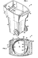
- the preferred embodiment of the present invention includes a housing 12 having an upper portion 14 with a generally rectangular cross section, and a lower portion 16 with a generally circular cross section. Accordingly, the lower portion 16 may be gripped from varying angles by mechanized gripper apparatus which are commonly used in fully mechanized methods.
- the upper portion 14 has a larger cross section than the lower portion 16 so as to form a horizontally projecting flange portion 18 generally about at least a portion of the circumference of the housing 12 at the intersection of the upper and lower portions 14, 16.
- the flange portion 18 aids in preventing the container from slipping out of the grasp of the mechanized gripper apparatus.
- the preferred embodiment includes a cover 20, which may be of varying configurations, hingedly attached at 22 to the top of the upper portion 14.
- a handle 24, which also may be of varying configurations, is further suitably attached to the top portion of the container.
- a pair of wheels 26 are mounted at the ends of an axle 28 retained in a cavity or channel 30 defined in the lower portion 16 of the housing 12. The wheel assembly enables the container to be readily wheeled from one location to another.
- the upper portion 14 includes proximate the front side of the container, a horizontally extending, downwardly opening channel or cavity 32 defined by a horizontally projecting portion 34 of the upper portion 14.
- the channel 32 provides a lift cavity for engagement by a lift bar apparatus of a garbage truck or the like such that the container may be emptied by a semi-mechanized or mechanized lift apparatus using a lift bar apparatus.
- the lower portion 16 of the preferred embodiment has a generally truncated, inverted conical configuration with curvilinear side walls generally diverging outwardly from the bottom to the top.
- the side walls of the upper portion 14 also diverge generally outwardly.
- the downwardly opening channel 32 overhangs the front side wall portion of the lower portion 16 such that there is unobstructed access to the channel 32 from the outside of the container and such that the channel 32 does not interfere with the unloading of garbage or the like on the inside of the container.
- the outwardly projecting portion 34 defines a lip portion 38 which provides one of the generally downwardly projecting walls of the channel 32. The lip portion 38 functions to retain the mechanized lift apparatus in the channel 32 during the unloading process.
- the channel 32 has a curvilinear upper portion 40 with generally straight side wall portions 42 and 44, the inside side wall 42 generally being in alignment with the side wall of the rectangular upper portion 14 and the lower portion 16 directly therebelow.
- the channel 32 will have a depth at least the diameter of the lift bar of the lift apparatus to assure that the lift bar does not slip out of the channel 32 during the lifting process. It will be appreciated that the lip portion 38 might extend further downward so as to provide the channel 32 with even greater depth.
- the channel 32 extends generally parallel to the side wall of the rectangular upper portion 14.
- the channel 32 preferably extends substantially the entire width of the front side of the housing 12 to increase the stability of the container on the lift bar. However, the channel 32 might extend across only a portion of the front side, which for example would be the case if the outwardly projecting portion 34 did not extend along the entire width of the front side.
- channel or cavity 32 might be formed by attaching a bracket apparatus to the side of the container whereby the bracket in cooperation with the container would form the channel 32.
- the cover 20 providing for ready access to the container.
- the handle 24 is suitably attached to the top of the container such that the container may be readily pivoted about the axle 28 and wheeled from one location to another.
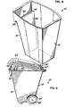
- the container of the present invention may be used with or without a handle and/or wheels as generally illustrated in FIG. 8. This will typically be the case in commercial applications where the container will be of relatively large size. Also, as illustrated in FIG. 8, the container in certain applications might only include a retangular portion 14' and no cylindrical portion 16.
- FIG. 9 Illustrated in FIG. 9 is yet another embodiment of the present invention which is made by a structural foam molding process to form a one piece integral container.
- the structural foam molding process enables the corners to be squared off as compared to the radiused corners of the blow molding process as illustrated in the other embodiments.
- the axle 28 is slideably retained within the cavity 30 near the bottom of the container.
- the cavity 30 is formed by an arcuate, concave portion 48 interconnecting a horizontal wall 50 and a vertical wall portion 52 of the lower portion 16.
- the vertical wall portion 52 includes a wall portion 52a extending directly below the axle 28 and a wall portion 52b offset inwardly from the wall 52a, the walls 52a, b being interconnected by an oblique, slanted wall portion 52c.
- This is a preferred wall configuration as it facilitates nesting of the containers during shipment. When nested, the wall 52b of an inside container nests inside the wall 52a of the outside container.
- the wall 52a has a length approximately one-third that of the walls 52a, b combined, the inside wall 52b being offset by approximately one -half inch.
- the preferred embodiment includes a bracket 33 near a midportion of the cavity which assists in retaining the axle 28 in the cavity 30.
- the horizontal and vertical walls 50, 52a, b, c form an indentation in the lower portion 16 across the back side of the container thereby enabling the container to be pivoted about the horizontally extending axle 28 such that the bottom back side of the lower portion 16 does not engage the surface of the ground so as to interfere with such pivotal motion.
- the preferred embodiment of the present invention has a bottom wall 21 which is slightly radiussed or concave to provide for a more ruggedized structure.
- the bottom wall 21 is displaced near a center portion thereof from the horizontal plane extending through the edges of the bottom wall 21 by roughly the thickness of the bottom wall 21.
- the wall thicknesses of the present invention are 1/4" to 3/8".
- the housing 12 of the preferred embodiment is made as a one piece, integral unit by a blow molding process. This reduces costs and enables relatively quick assembly and manufacture.
- the container is made from an industrial grade polyethylene material which has good weathering properties.
- the present invention might also be made by a rotational molding process or a structural foam molding process or other suitable plastic molding processes.
- the container might also be made of other materials such as metal or the like.
- the containers might be sent to customers in a nested configuration without the axle 28, the cover 20, and/or the handle 24 attached. The customer will then assemble the containers after receipt thereof.
- the present invention provides a portable refuse container which is easily wheeled from one location to another and which enables use with various types of manual, semi-mechanized, and mechanized lift apparatus.
- the container may be dimensional to readily fit through fence gates, doors, etc. thereby being readily adaptable for residential use.
- the continer might have a ninety gallon capacity and in commercial or multiple family residential use it might have a three hundred gallon capacity.
- the present invention is relatively inexpensive to manufacture and lends itself to both residential and commercial use.
Landscapes
- Engineering & Computer Science (AREA)
- Mechanical Engineering (AREA)
- Refuse Receptacles (AREA)
- Devices For Use In Laboratory Experiments (AREA)
- Secondary Cells (AREA)
- Sampling And Sample Adjustment (AREA)
- Magnetic Resonance Imaging Apparatus (AREA)
- Prostheses (AREA)
Priority Applications (1)
| Application Number | Priority Date | Filing Date | Title |
|---|---|---|---|
| AT84850010T ATE31698T1 (de) | 1983-10-12 | 1984-01-12 | Behaelter mit rechteckigem/kreisfoermigem querschnitt. |
Applications Claiming Priority (2)
| Application Number | Priority Date | Filing Date | Title |
|---|---|---|---|
| US54126883A | 1983-10-12 | 1983-10-12 | |
| US541268 | 2000-04-03 |
Publications (3)
| Publication Number | Publication Date |
|---|---|
| EP0138780A2 true EP0138780A2 (de) | 1985-04-24 |
| EP0138780A3 EP0138780A3 (en) | 1985-07-03 |
| EP0138780B1 EP0138780B1 (de) | 1988-01-07 |
Family
ID=24158882
Family Applications (1)
| Application Number | Title | Priority Date | Filing Date |
|---|---|---|---|
| EP84850010A Expired EP0138780B1 (de) | 1983-10-12 | 1984-01-12 | Behälter mit rechteckigem/kreisförmigem Querschnitt |
Country Status (5)
| Country | Link |
|---|---|
| EP (1) | EP0138780B1 (de) |
| AT (1) | ATE31698T1 (de) |
| CA (1) | CA1238871A (de) |
| DE (1) | DE3468399D1 (de) |
| IT (1) | IT8420964V0 (de) |
Cited By (4)
| Publication number | Priority date | Publication date | Assignee | Title |
|---|---|---|---|---|
| US4907710A (en) * | 1988-02-16 | 1990-03-13 | Bulkens Catherine S | Trash can with integral dustpan for utilization of plastic liners with handles |
| US5088750A (en) * | 1990-04-30 | 1992-02-18 | Otto Industries, Inc. | Multi-functional waste container |
| US5251779A (en) * | 1989-01-25 | 1993-10-12 | Stefan Schmidt | Trash container |
| US7017773B2 (en) | 2002-09-09 | 2006-03-28 | Rehrig Pacific Company | Waste container |
Families Citing this family (1)
| Publication number | Priority date | Publication date | Assignee | Title |
|---|---|---|---|---|
| DE10344516A1 (de) * | 2003-09-24 | 2005-04-28 | Sulo Umwelttechnik Gmbh & Co Kg | Müllbehälter und Aufnahmevorrichtung mit erhöhter Aufnahmetoleranz |
Family Cites Families (6)
| Publication number | Priority date | Publication date | Assignee | Title |
|---|---|---|---|---|
| DE6909469U (de) * | 1969-03-07 | 1969-09-18 | Misch Und Transportanlagen G M | Muellbehaelter |
| US3804277A (en) * | 1973-03-09 | 1974-04-16 | Rubbermaid Ind Prod Corp | Waste receptacle and dumping mechanism therefor |
| GB1491861A (en) * | 1975-01-24 | 1977-11-16 | Moran K | Wheeled articles |
| US4042137A (en) * | 1976-04-08 | 1977-08-16 | Thomas Philip Hughes | Municipal refuse collection system |
| US4401312A (en) * | 1981-03-23 | 1983-08-30 | Parker Bruce H | Automated trash collection receptacle |
| GB2119723B (en) * | 1982-05-06 | 1985-09-25 | Glasdon Ltd | Moulded plastics bin |
-
1984
- 1984-01-12 DE DE8484850010T patent/DE3468399D1/de not_active Expired
- 1984-01-12 AT AT84850010T patent/ATE31698T1/de active
- 1984-01-12 EP EP84850010A patent/EP0138780B1/de not_active Expired
- 1984-02-22 IT IT8420964U patent/IT8420964V0/it unknown
- 1984-10-10 CA CA000465032A patent/CA1238871A/en not_active Expired
Cited By (5)
| Publication number | Priority date | Publication date | Assignee | Title |
|---|---|---|---|---|
| US4907710A (en) * | 1988-02-16 | 1990-03-13 | Bulkens Catherine S | Trash can with integral dustpan for utilization of plastic liners with handles |
| US5251779A (en) * | 1989-01-25 | 1993-10-12 | Stefan Schmidt | Trash container |
| US5088750A (en) * | 1990-04-30 | 1992-02-18 | Otto Industries, Inc. | Multi-functional waste container |
| US7017773B2 (en) | 2002-09-09 | 2006-03-28 | Rehrig Pacific Company | Waste container |
| US8448812B2 (en) | 2002-09-09 | 2013-05-28 | Rehrig Pacific Company | Waste container with base member |
Also Published As
| Publication number | Publication date |
|---|---|
| CA1238871A (en) | 1988-07-05 |
| IT8420964V0 (it) | 1984-02-22 |
| ATE31698T1 (de) | 1988-01-15 |
| EP0138780A3 (en) | 1985-07-03 |
| EP0138780B1 (de) | 1988-01-07 |
| DE3468399D1 (en) | 1988-02-11 |
Similar Documents
| Publication | Publication Date | Title |
|---|---|---|
| US5323923A (en) | Waste container | |
| US5088750A (en) | Multi-functional waste container | |
| US4630752A (en) | Trash can hoop retainer | |
| US4660876A (en) | Reusable bottle handle | |
| US4411300A (en) | Flexible bag with frame | |
| US5547104A (en) | Waste container with dump handle | |
| US5222704A (en) | Bag support device for supporting a bag within a trash container | |
| US5425467A (en) | Bowl lid having integral lever mechanism | |
| US4401312A (en) | Automated trash collection receptacle | |
| US4992018A (en) | Refuse container for use with emptying mechanism | |
| US4666054A (en) | Animal proof storage container apparatus | |
| US4135725A (en) | Removable wheel and handle apparatus for trash receptacles | |
| CA2496771A1 (en) | Waste container | |
| US4712701A (en) | Super-elliptical adaptor ring for refuse containers and the like | |
| US12180000B2 (en) | Refuse container | |
| US6199452B1 (en) | Pail opener and resealer device | |
| US5295419A (en) | Pry device adapted for removing container lids | |
| EP0138780A2 (de) | Behälter mit rechteckigem/kreisförmigem Querschnitt | |
| US5251944A (en) | Pull handle for recycling bin | |
| US11724875B2 (en) | Two-part garbage can with handles on the base | |
| US5123562A (en) | Side discharge trash container | |
| US20030183633A1 (en) | Container lid lifting device | |
| US5568750A (en) | Lid Lifter | |
| US4741073A (en) | Collapsible handle for carton | |
| US4116362A (en) | Lid lifting tool for shipping containers |
Legal Events
| Date | Code | Title | Description |
|---|---|---|---|
| PUAI | Public reference made under article 153(3) epc to a published international application that has entered the european phase |
Free format text: ORIGINAL CODE: 0009012 |
|
| AK | Designated contracting states |
Designated state(s): AT BE CH DE FR GB IT LI LU NL SE |
|
| PUAL | Search report despatched |
Free format text: ORIGINAL CODE: 0009013 |
|
| AK | Designated contracting states |
Designated state(s): AT BE CH DE FR GB IT LI LU NL SE |
|
| 17P | Request for examination filed |
Effective date: 19851220 |
|
| 17Q | First examination report despatched |
Effective date: 19860821 |
|
| GRAA | (expected) grant |
Free format text: ORIGINAL CODE: 0009210 |
|
| AK | Designated contracting states |
Kind code of ref document: B1 Designated state(s): AT BE CH DE FR GB IT LI LU NL SE |
|
| PG25 | Lapsed in a contracting state [announced via postgrant information from national office to epo] |
Ref country code: NL Effective date: 19880107 |
|
| REF | Corresponds to: |
Ref document number: 31698 Country of ref document: AT Date of ref document: 19880115 Kind code of ref document: T |
|
| ITF | It: translation for a ep patent filed | ||
| PG25 | Lapsed in a contracting state [announced via postgrant information from national office to epo] |
Ref country code: LU Free format text: LAPSE BECAUSE OF NON-PAYMENT OF DUE FEES Effective date: 19880131 |
|
| REF | Corresponds to: |
Ref document number: 3468399 Country of ref document: DE Date of ref document: 19880211 |
|
| ET | Fr: translation filed | ||
| NLV1 | Nl: lapsed or annulled due to failure to fulfill the requirements of art. 29p and 29m of the patents act | ||
| PLBE | No opposition filed within time limit |
Free format text: ORIGINAL CODE: 0009261 |
|
| STAA | Information on the status of an ep patent application or granted ep patent |
Free format text: STATUS: NO OPPOSITION FILED WITHIN TIME LIMIT |
|
| 26N | No opposition filed | ||
| ITTA | It: last paid annual fee | ||
| PGFP | Annual fee paid to national office [announced via postgrant information from national office to epo] |
Ref country code: FR Payment date: 19901215 Year of fee payment: 8 |
|
| PGFP | Annual fee paid to national office [announced via postgrant information from national office to epo] |
Ref country code: DE Payment date: 19901217 Year of fee payment: 8 Ref country code: AT Payment date: 19901217 Year of fee payment: 8 |
|
| PGFP | Annual fee paid to national office [announced via postgrant information from national office to epo] |
Ref country code: CH Payment date: 19901218 Year of fee payment: 8 |
|
| PGFP | Annual fee paid to national office [announced via postgrant information from national office to epo] |
Ref country code: SE Payment date: 19901219 Year of fee payment: 8 |
|
| PGFP | Annual fee paid to national office [announced via postgrant information from national office to epo] |
Ref country code: LU Payment date: 19901227 Year of fee payment: 8 Ref country code: BE Payment date: 19901227 Year of fee payment: 8 |
|
| PGFP | Annual fee paid to national office [announced via postgrant information from national office to epo] |
Ref country code: GB Payment date: 19910102 Year of fee payment: 8 |
|
| EPTA | Lu: last paid annual fee | ||
| PG25 | Lapsed in a contracting state [announced via postgrant information from national office to epo] |
Ref country code: GB Effective date: 19920112 Ref country code: AT Effective date: 19920112 |
|
| PG25 | Lapsed in a contracting state [announced via postgrant information from national office to epo] |
Ref country code: SE Effective date: 19920113 |
|
| PG25 | Lapsed in a contracting state [announced via postgrant information from national office to epo] |
Ref country code: LI Effective date: 19920131 Ref country code: CH Effective date: 19920131 Ref country code: BE Effective date: 19920131 |
|
| BERE | Be: lapsed |
Owner name: REUTER INC. Effective date: 19920131 |
|
| GBPC | Gb: european patent ceased through non-payment of renewal fee | ||
| PG25 | Lapsed in a contracting state [announced via postgrant information from national office to epo] |
Ref country code: FR Effective date: 19920930 |
|
| REG | Reference to a national code |
Ref country code: CH Ref legal event code: PL |
|
| PG25 | Lapsed in a contracting state [announced via postgrant information from national office to epo] |
Ref country code: DE Effective date: 19921001 |
|
| REG | Reference to a national code |
Ref country code: FR Ref legal event code: ST |
|
| EUG | Se: european patent has lapsed |
Ref document number: 84850010.4 Effective date: 19920806 |