EP0138996B1 - Dispositif a tambour pour la fabrication de dragees - Google Patents
Dispositif a tambour pour la fabrication de dragees Download PDFInfo
- Publication number
- EP0138996B1 EP0138996B1 EP84901749A EP84901749A EP0138996B1 EP 0138996 B1 EP0138996 B1 EP 0138996B1 EP 84901749 A EP84901749 A EP 84901749A EP 84901749 A EP84901749 A EP 84901749A EP 0138996 B1 EP0138996 B1 EP 0138996B1
- Authority
- EP
- European Patent Office
- Prior art keywords
- drum
- bearing
- coating device
- pivotal
- ring
- Prior art date
- Legal status (The legal status is an assumption and is not a legal conclusion. Google has not performed a legal analysis and makes no representation as to the accuracy of the status listed.)
- Expired
Links
- 239000006187 pill Substances 0.000 title claims 2
- 238000004519 manufacturing process Methods 0.000 title abstract description 4
- 238000007789 sealing Methods 0.000 claims abstract description 6
- 239000011248 coating agent Substances 0.000 claims description 41
- 238000000576 coating method Methods 0.000 claims description 41
- 230000008878 coupling Effects 0.000 claims description 6
- 238000010168 coupling process Methods 0.000 claims description 6
- 238000005859 coupling reaction Methods 0.000 claims description 6
- 239000008187 granular material Substances 0.000 claims description 5
- 238000001035 drying Methods 0.000 claims description 3
- 239000000463 material Substances 0.000 claims description 2
- 239000000725 suspension Substances 0.000 claims description 2
- 230000000717 retained effect Effects 0.000 claims 4
- 238000005096 rolling process Methods 0.000 abstract description 5
- 238000010276 construction Methods 0.000 abstract description 4
- 230000000694 effects Effects 0.000 abstract description 3
- 238000007667 floating Methods 0.000 description 8
- 238000000034 method Methods 0.000 description 5
- 230000008569 process Effects 0.000 description 5
- 230000007704 transition Effects 0.000 description 5
- 238000003860 storage Methods 0.000 description 3
- 230000008901 benefit Effects 0.000 description 2
- 230000008859 change Effects 0.000 description 2
- 235000009508 confectionery Nutrition 0.000 description 2
- 230000005540 biological transmission Effects 0.000 description 1
- 238000004140 cleaning Methods 0.000 description 1
- 238000006073 displacement reaction Methods 0.000 description 1
- 238000009826 distribution Methods 0.000 description 1
- 239000008298 dragée Substances 0.000 description 1
- 238000009434 installation Methods 0.000 description 1
- 230000002093 peripheral effect Effects 0.000 description 1
- 230000035939 shock Effects 0.000 description 1
Images



Classifications
-
- F—MECHANICAL ENGINEERING; LIGHTING; HEATING; WEAPONS; BLASTING
- F16—ENGINEERING ELEMENTS AND UNITS; GENERAL MEASURES FOR PRODUCING AND MAINTAINING EFFECTIVE FUNCTIONING OF MACHINES OR INSTALLATIONS; THERMAL INSULATION IN GENERAL
- F16C—SHAFTS; FLEXIBLE SHAFTS; ELEMENTS OR CRANKSHAFT MECHANISMS; ROTARY BODIES OTHER THAN GEARING ELEMENTS; BEARINGS
- F16C23/00—Bearings for exclusively rotary movement adjustable for aligning or positioning
- F16C23/06—Ball or roller bearings
- F16C23/08—Ball or roller bearings self-adjusting
-
- A—HUMAN NECESSITIES
- A23—FOODS OR FOODSTUFFS; TREATMENT THEREOF, NOT COVERED BY OTHER CLASSES
- A23G—COCOA; COCOA PRODUCTS, e.g. CHOCOLATE; SUBSTITUTES FOR COCOA OR COCOA PRODUCTS; CONFECTIONERY; CHEWING GUM; ICE-CREAM; PREPARATION THEREOF
- A23G3/00—Sweetmeats; Confectionery; Marzipan; Coated or filled products
- A23G3/02—Apparatus specially adapted for manufacture or treatment of sweetmeats or confectionery; Accessories therefor
- A23G3/20—Apparatus for coating or filling sweetmeats or confectionery
- A23G3/26—Apparatus for coating by tumbling with a liquid or powder, spraying device-associated, drum, rotating pan
-
- F—MECHANICAL ENGINEERING; LIGHTING; HEATING; WEAPONS; BLASTING
- F16—ENGINEERING ELEMENTS AND UNITS; GENERAL MEASURES FOR PRODUCING AND MAINTAINING EFFECTIVE FUNCTIONING OF MACHINES OR INSTALLATIONS; THERMAL INSULATION IN GENERAL
- F16C—SHAFTS; FLEXIBLE SHAFTS; ELEMENTS OR CRANKSHAFT MECHANISMS; ROTARY BODIES OTHER THAN GEARING ELEMENTS; BEARINGS
- F16C13/00—Rolls, drums, discs, or the like; Bearings or mountings therefor
- F16C13/02—Bearings
Definitions
- the invention relates to a coating device for coating granules such as dragee cores with a multi-layer coating, with a coating drum, preferably held about a horizontal axis in two axially offset rotary bearings, connected to a drum drive, in the particular embodiment specified in claim 1.
- the invention is based on the coating device described at the outset and has the object of developing this device in the simplest possible way in such a way that the costs of storage and the axial and edge loads to be accommodated on both bearings are reduced and the service life of the drum bearing and thereby the coating drum is increased .
- the automatic axial adjustability provided on the floating bearing with the swivel adjustability is of practical importance in the case of changing temperature differences between the drum and the environment or of a frame or a base plate carrying the drum. Such temperature differences can practically only arise during the breaks.
- the floating bearing since large drums - apart from quick unloading and loading processes - are set up for continuous operation, the floating bearing generally maintains its axial position once it has been in use after an initial temperature control process.
- FR-A 788 167 shows such a bearing with an outer frame pivotably mounted about a horizontal first axis, which rotatably holds an inner frame about a second axis arranged perpendicular to the first axis, in which a bearing is provided in a third axis perpendicular to both axes is, which can also be designed as a roller bearing.
- edge pressures per se can be avoided, but the stresses in the two pivot bearings of a coating drum, which are arranged at a distance from one another, are coordinated with them However, this is not easily possible.
- the gimbal comprises an outer gimbal, which is held in a fixed support via two coaxial pivots about a first pivot axis and carries an inner gimbal that is pivotably adjustable about a first vertical second pivot axis and is connected to the outer roller bearing ring .
- the inner gimbal can then sit directly on a drum hub.
- support or coupling means are provided between the inner gimbal and the coating drum for directly supporting or locking the drum in its rotational position, which can be important for unloading and loading processes, for overall cleaning processes, but above all for assembly processes.
- the non-rotatably arranged parts of the flow distributor are at least indirectly guided in the transition surface to the drum in such a way that it can be adjusted automatically.
- This can be accomplished in a relatively simple manner in that the non-rotatable parts of the flow distributor are connected to the non-rotatable part of a drum bearing, in particular the fixed bearing, which can be adjusted automatically to the drum.
- the non-rotatable parts of the flow distributor With an inclined position of the axis of the associated drum hub as a result of a deflection in the central drum part, the non-rotatable parts of the flow distributor, which anyway have to be held against rotation, are adjusted in the inclined position of the axis, which results in an inclined position of the transition surface.
- the non-rotatable parts should in any case be firmly connected to the inner gimbal ring, with for example an annular disk connected to the inner end of the inner ring, in particular by means of radially projecting connecting arms, being connected to the non-rotatable part of the flow distributor.
- a torus surface that is central to this can be provided. It is understood that two rings can be provided here, the torus surface having the shape of a spherical ring surface, the center of which lies in the axis of the drum hub. However, it is simpler to convexly curve the toroidal surface provided on the inner part of the second pivot bearing and to allow the cylinder surface to encompass with the circumferential inclination play. In principle, this only results in a punctiform support that only increases to a few mm support surface under load, but the only relative movement is likely to be an axial displacement of less than 1 mm during breaks in operation.
- the coating device shown essentially consists of a machine frame 1, the coating drum 2, a drive device 3, a flow distributor 4 with a connection (not shown further) to a suction and pressure blower, an application device, of which only the mass supply line 5 is shown here, and one housing 6 enclosing drum 2 on machine frame 1.
- the main component of the machine frame 1 is a base plate 11 designed as a box hollow construction, which is held on the installation surface 13 by means of feet 12 which can be adjusted in the vertical direction and by means of a front bearing stand 14 in the manner shown in FIG. 4 and a floating bearing 15 and by means of a rear bearing stand 16 holds a fixed bearing 17, as shown in detail in FIGS. 2 and 5.
- the coating device with the coating drum 2 corresponds to the version according to the German laid-open specification 31 31 808. However, while a nine-corner drum was used there, a twelve-corner drum is used here. Accordingly, there are twelve guide channels 18, each with air passages 19 of different designs in connection with the drum interior and at their right end in FIG. 1 with a connecting chamber 21 of the drum flangeed into an end flange 22 of the drum and sealed against this rotatable part 23 of the drum Flow distributor 4 are connected.
- the rotatable part is surrounded by the non-rotatable part 25 in a sealed manner by means of lateral sealing segments 26.
- This non-rotatable part is composed of a lower segment groove 27 and an upper segment groove 28, which have two connecting elbows 29, 31, opposite each other each extend over approximately 180 ° and against one another by strip seals 32 are shielded. In principle, it could therefore be blown in on half the circumference and removed or extracted on the opposite half circumference.
- each chamber 21 is separated from the lower segment groove 27 at approximately the circumference of the coating drum in a clockwise direction according to FIG. 6 in the region of the angle c before it comes into contact with the upper segment groove in the region of the connection angle b.
- connection elbow 29 or 31 is connected to pressure or to vacuum, the granulate bed is flowed through from below or from above.
- the coating drum can be loaded in a known manner through the drum hub 36 closed off by the cover 35 or in another way.
- a wall part is expediently folded out, so that the entire batch of drums can fall into the funnel 37 which is fixed or movable in the machine frame.
- the bearing hub 36 is, as primarily shown in FIG. 4, surrounded by the frame opening 30 of the bearing stand 14 welded together from square tubes.
- This frame opening is largely filled by a bearing plate 38 attached to the inside of the bearing stand 14, which holds the cover 35 by means of a pipe socket 39 and to which the outer ring 41 of the floating bearing 15 is flanged.
- the inner ring 42 is firmly screwed to an adjusting ring 43, which forms a convexly curved torus surface 44 on the inside, on which the outer cylindrical surface 45 of the drum hub 36 is supported with a circumferential play that allows inclination.
- a coupling pin 46 clamped on or between the two rings is used, which projects axially to the right in FIG. 5 into a radial groove 47 of a fork piece 48, which is at an axial distance e from the inner ring 42 the bearing hub 36 is attached.
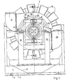
- the bearing stand 16 for the fixed bearing 17 is made of square tubes and thus rigid and relatively rigid. There, however, the bearing is not enclosed in a frame-like manner, but the uprights 161 end at a distance below the drum axis 49 and, by means of two pivot bearings 50, pivotably adjust an outer gimbal 53 which is in turn formed by rectangular tubes in and in a horizontal axis 52 which intersects the drum axis 49 essentially at right angles one of the two axes 19 and 52 intersecting at right angles, the second vertical pivot axis 51 carries an inner gimbal 55. 3 is fixedly connected to the outer ring 141 of the fixed bearing 17, which has the same design as the floating bearing 15. The inner ring 142 is then also fixedly connected to a chain drive wheel 56, which in turn is seated firmly on the drum hub 57 .
- two hinge pins 58 each pass through the gimbal frame 53 and the gimbal ring 55.
- Both hinge pins 58 are each seated with their thread 61 in the gimbal 55 and can be adjusted axially until their conical tip 62 engages in a countersink 63 of the bearing hub 57 and thereby rotatably locks the drum in the machine frame or slightly raises it. In this way, assembly and disassembly are made considerably easier since the bearing 17 can be relieved by supporting it in the gimbal. You can replace the bearing 17 and the chain drive wheel 56 without using a special hoist.
- the drum hub 57 which can be rotated in the almost exclusively radially stressed fixed bearing 17, is clearly defined in the axial direction by the support via the inner ring 142, the pivot pin 58, the gimbal frame 53 and the pivot bearing 50 on the bearing stand 16 and thus on the machine frame.
- the fixed bearing 17 and, on the other hand, the floating bearing 15 each have a connection with all-round adjustability, ie H. both drum hubs 36 and 57 are freely adjustable.
- the coating drum 2 can therefore bend almost at will and can be built accordingly light.
- the outer, non-rotatable part 25 of the flow distributor 4 can in principle be rotatably supported on the inner part 23, provided that it is only supported against rotation. However, since this would require additional axial space, this non-rotatable part is fastened to a disk 69 by means of individual screws 67, possibly by means of individual star-shaped arms 68, which in turn is firmly connected to the gimbal 55 via an intermediate ring 71.
- the non-rotatable part 25 of the flow distributor follows the rotatable part 23 when the drum bends and accordingly the drum hub 57 is inclined.
- sealing means such as the sealing plates, the inner part and outer part do not need to touch, they are assigned to one another with a small clearance.
- the attachment of the rotatable part formed from the two segment grooves 27 and 28 to individual screws 67 provided with a constant circumferential pitch also has the advantage that the "non-rotatable part" 25 can be pivoted as desired about the drum axis and thereby caused by a different inclination of the surface of the can adjust granule bed treated in the drum.
- a direct attachment of the two segment channels to each other is not even necessary.
- the length of the cover can also be changed by the two screens 33, 34 either by making these screens adjustable or by exchanging them as required.
- the interior of the coating drum is also connected to the atmosphere via the angled tube piece 77 which adjoins the drum hub 57.
- this piece of pipe can also be used for supplying air under pressure if, for any reason, the flow path should not lead over the segment groove 28.
- sealing segments 26 and strip seals 32 always enclose the connection openings of the segment grooves 27, 28 and also close these connection openings in the cylindrical circumferential surface 24, suction and pressure paths are exactly separated from one another, and there is also a complete seal against outside air in the Flow distributor 4 guaranteed.
- the interior of the coating drum 2 can in principle be completely closed off from the atmosphere, so that work is carried out directly or within the surrounding housing in the recirculation mode.
- the degree of closure can also be changed by throttling in the flow path of the angle tube piece 77.
- the seal itself can be simplified even more if, according to FIG. 7, two ring seals in the form of ring hoses 80 are attached between rotatable and non-rotatable parts, which consist of relatively soft, rubber-like deformable material with a smooth, sliding surface.
- These ring tubes can be designed in the manner of bicycle tubes and can also be provided with a valve 81 in order to be inflated to the desired internal pressure.
- the strip seals 32 can remain modified and the segment grooves 27, 28 can be shielded gas-tight from the interior of the drum surfaces.
- these strip seals can also be molded in one piece on the ring hoses 80.
Landscapes
- Engineering & Computer Science (AREA)
- General Engineering & Computer Science (AREA)
- Mechanical Engineering (AREA)
- Life Sciences & Earth Sciences (AREA)
- Chemical & Material Sciences (AREA)
- Food Science & Technology (AREA)
- Polymers & Plastics (AREA)
- Glanulating (AREA)
- Medical Preparation Storing Or Oral Administration Devices (AREA)
- Confectionery (AREA)
Abstract
Claims (15)
Applications Claiming Priority (2)
| Application Number | Priority Date | Filing Date | Title |
|---|---|---|---|
| DE3310031 | 1983-03-19 | ||
| DE19833310031 DE3310031A1 (de) | 1983-03-19 | 1983-03-19 | Dragiervorrichtung mit dragiertrommel |
Publications (2)
| Publication Number | Publication Date |
|---|---|
| EP0138996A1 EP0138996A1 (fr) | 1985-05-02 |
| EP0138996B1 true EP0138996B1 (fr) | 1987-06-10 |
Family
ID=6194064
Family Applications (2)
| Application Number | Title | Priority Date | Filing Date |
|---|---|---|---|
| EP84901749A Expired EP0138996B1 (fr) | 1983-03-19 | 1984-03-13 | Dispositif a tambour pour la fabrication de dragees |
| EP84200451A Withdrawn EP0119672A1 (fr) | 1983-03-19 | 1984-03-13 | Machine à dragéifier à tambour |
Family Applications After (1)
| Application Number | Title | Priority Date | Filing Date |
|---|---|---|---|
| EP84200451A Withdrawn EP0119672A1 (fr) | 1983-03-19 | 1984-03-13 | Machine à dragéifier à tambour |
Country Status (5)
| Country | Link |
|---|---|
| US (1) | US4586457A (fr) |
| EP (2) | EP0138996B1 (fr) |
| JP (1) | JPS60500894A (fr) |
| DE (2) | DE3310031A1 (fr) |
| WO (1) | WO1984003609A1 (fr) |
Families Citing this family (17)
| Publication number | Priority date | Publication date | Assignee | Title |
|---|---|---|---|---|
| FR2618041B1 (fr) * | 1987-07-16 | 1991-06-21 | Ceres Ets | Dispositif pour le traitement des semences |
| JP3031924B2 (ja) * | 1989-07-07 | 2000-04-10 | フロイント産業株式会社 | 造粒コーティング装置 |
| DE4036668C2 (de) * | 1990-11-17 | 1997-09-11 | Driam Metallprodukt Gmbh & Co | Beschichtungsmaschie mit Gegenstrom- und Gleichstrom-Luftführung |
| US5433964A (en) * | 1991-08-06 | 1995-07-18 | Borden, Inc. | Process of coating strandula food |
| JP3347767B2 (ja) * | 1992-07-10 | 2002-11-20 | フロイント産業株式会社 | パンコーティング装置 |
| US5495418A (en) * | 1993-06-18 | 1996-02-27 | Latini Machine Company | Automatic panning system |
| US5443637A (en) * | 1993-09-17 | 1995-08-22 | Coating Machinery Systems, Inc. | Means for continuously coating particulate material |
| JPH07163853A (ja) * | 1993-10-12 | 1995-06-27 | Freunt Ind Co Ltd | 粉粒体コーティング装置 |
| JP3349580B2 (ja) * | 1994-03-03 | 2002-11-25 | フロイント産業株式会社 | パンコーティング装置 |
| US6142095A (en) * | 1998-06-03 | 2000-11-07 | Coating Machinery Systems, Inc. | Machine for coating particulate material |
| DE10011795A1 (de) * | 2000-03-14 | 2001-09-20 | Stoever Produktion Gmbh & Co K | Verfahren zum Coating (Beschichtung) eines Kartoffelproduktes |
| US6511541B2 (en) | 2001-02-27 | 2003-01-28 | Spray Dynamics, Ltd. | Powder applicator for particulate material coating |
| US7066187B2 (en) * | 2001-09-15 | 2006-06-27 | Mueller Alois | Modular treatment plant having horizontal drum machines |
| US20030165614A1 (en) * | 2002-03-01 | 2003-09-04 | Henrik Hansen | Coating a medical implant using a pan coater |
| IT1400396B1 (it) | 2010-06-08 | 2013-05-31 | Perfetti Van Melle Spa | Metodo ed impianto per il rivestimento di prodotti edibili. |
| ES2390299B1 (es) * | 2010-11-26 | 2013-10-10 | Fundación Centro De Tecnologías Aeronáuticas | Sistema para aplicación de cargas de flexión en un eje rotativo |
| RU189230U1 (ru) * | 2018-10-09 | 2019-05-16 | Общество с ограниченной ответственностью "Воронежсельмаш" | Устройство для дражирования семян |
Family Cites Families (11)
| Publication number | Priority date | Publication date | Assignee | Title |
|---|---|---|---|---|
| FR963049A (fr) * | 1950-06-28 | |||
| US2734406A (en) * | 1956-02-14 | q malley | ||
| FR788167A (fr) * | 1934-07-04 | 1935-10-05 | Fonderie Nouvelle | Coussinet à cardan |
| DE1170357B (de) * | 1960-12-30 | 1964-05-21 | Siemag Siegener Masch Bau | Lageranordnung fuer die Richtwalzen an Blechrichtmaschinen |
| GB1114405A (en) * | 1964-09-19 | 1968-05-22 | Walther Technik Carl Kurt Walt | Apparatus for acting on components for the purpose of surface coating,polishing,grinding or mixing |
| DE2212985A1 (de) * | 1972-03-17 | 1973-09-20 | Manfred Sauter | Drageemaschine |
| US3923349A (en) * | 1973-06-25 | 1975-12-02 | Lord Corp | Universal bearing support |
| DE2805801A1 (de) * | 1978-02-11 | 1979-08-16 | Driam Metallprodukt Gmbh & Co | Vorrichtung zum beschichten von granulaten wie drageekerne mit einer huelle und zum antrocknen der huelle durch trocknungsluft |
| CH631643A5 (de) * | 1978-04-14 | 1982-08-31 | Fischer Ag Georg | Verfahren zur regenerierung von giesserei-altsand sowie einrichtung zur durchfuehrung des verfahrens und erzeugnis des verfahrens. |
| JPS5544380A (en) * | 1978-09-26 | 1980-03-28 | Okawara Mfg Co Ltd | Drafty rotary drum type coater |
| DE3131808C2 (de) * | 1981-08-12 | 1987-04-09 | Driam Metallprodukt Gmbh & Co Kg, 7991 Eriskirch | Vorrichtung zum Beschichten von Granulaten wie Drageekerne mit einer Hülle und zum Austrocknen dieser Hülle |
-
1983
- 1983-03-19 DE DE19833310031 patent/DE3310031A1/de not_active Withdrawn
-
1984
- 1984-03-13 JP JP59501810A patent/JPS60500894A/ja active Granted
- 1984-03-13 EP EP84901749A patent/EP0138996B1/fr not_active Expired
- 1984-03-13 EP EP84200451A patent/EP0119672A1/fr not_active Withdrawn
- 1984-03-13 US US06/676,396 patent/US4586457A/en not_active Expired - Lifetime
- 1984-03-13 DE DE8484901749T patent/DE3464114D1/de not_active Expired
- 1984-03-13 WO PCT/EP1984/000072 patent/WO1984003609A1/fr not_active Ceased
Also Published As
| Publication number | Publication date |
|---|---|
| WO1984003609A1 (fr) | 1984-09-27 |
| DE3310031A1 (de) | 1984-09-20 |
| DE3464114D1 (en) | 1987-07-16 |
| JPS6219135B2 (fr) | 1987-04-27 |
| EP0138996A1 (fr) | 1985-05-02 |
| JPS60500894A (ja) | 1985-06-20 |
| US4586457A (en) | 1986-05-06 |
| EP0119672A1 (fr) | 1984-09-26 |
Similar Documents
| Publication | Publication Date | Title |
|---|---|---|
| EP0119672A1 (fr) | Machine à dragéifier à tambour | |
| DE2918762C2 (de) | Vorrichtung zum Überziehen bzw. Kandieren von körnigem Gut | |
| DE3131808C2 (de) | Vorrichtung zum Beschichten von Granulaten wie Drageekerne mit einer Hülle und zum Austrocknen dieser Hülle | |
| DE69420808T2 (de) | Einrichtung zur Umhüllung von körnigem Material | |
| DE2805801C2 (fr) | ||
| EP0564851B1 (fr) | Dispositif pour le chargement de matières en vrac | |
| CH654086A5 (de) | Schuesselmuehlengetriebe. | |
| DE69200838T2 (de) | Selbstpositionierende durchbiegungseinstellwalze. | |
| DE4431501A1 (de) | Fahrzeugmischer für fließfähige Medien, wie Beton | |
| EP0171527B1 (fr) | Machine de finissage centrifuge | |
| EP0234423B1 (fr) | Support réglable en hauteur pour semi-remorque | |
| DE2348077C2 (de) | Antrieb für eine in einem Schachtofen - insbesondere Hochofenkopf-angeordnete Verteilerschurre | |
| DE2854710C2 (de) | Trockenpatrone | |
| EP0072467A1 (fr) | Appareil d'enrobage de dragées | |
| DE2550366A1 (de) | Durchbiegungsausgleichwalze | |
| DE2643653C2 (de) | Vorrichtung an mindestens zwei im Winkel zueinander angeordneten Förderern | |
| DE2040568C3 (de) | Vorrichtung zum Fördern von Behältern mit sterilisierbarem Füllgut | |
| EP0861118A1 (fr) | Dispositif pour retirer une matiere en vrac contenue dans un recipient sous pression | |
| DE4330206A1 (de) | Vorrichtung zur Verteilung von pulverförmigen Stoffen | |
| EP0029599B1 (fr) | Convoyeur pour le déchargement abrupt de navires et autres conteneurs | |
| EP0039487B1 (fr) | Convoyeur pour le déchargement de navires et autres citernes | |
| EP0642900A1 (fr) | Mélangeur monté sur véhicule pour mélanges aptes à couler comme du béton | |
| DE4237419C2 (de) | Rohrweiche für pneumatisch zu fördernde Schüttgüter | |
| EP0401333B1 (fr) | Vehicule a elements multiples, notamment autobus articule | |
| CH645281A5 (en) | Agitator mill |
Legal Events
| Date | Code | Title | Description |
|---|---|---|---|
| PUAI | Public reference made under article 153(3) epc to a published international application that has entered the european phase |
Free format text: ORIGINAL CODE: 0009012 |
|
| 17P | Request for examination filed |
Effective date: 19850124 |
|
| AK | Designated contracting states |
Designated state(s): DE FR GB |
|
| GRAA | (expected) grant |
Free format text: ORIGINAL CODE: 0009210 |
|
| AK | Designated contracting states |
Kind code of ref document: B1 Designated state(s): DE FR GB |
|
| REF | Corresponds to: |
Ref document number: 3464114 Country of ref document: DE Date of ref document: 19870716 |
|
| ET | Fr: translation filed | ||
| PLBE | No opposition filed within time limit |
Free format text: ORIGINAL CODE: 0009261 |
|
| STAA | Information on the status of an ep patent application or granted ep patent |
Free format text: STATUS: NO OPPOSITION FILED WITHIN TIME LIMIT |
|
| 26N | No opposition filed | ||
| REG | Reference to a national code |
Ref country code: GB Ref legal event code: IF02 |
|
| PGFP | Annual fee paid to national office [announced via postgrant information from national office to epo] |
Ref country code: GB Payment date: 20030227 Year of fee payment: 20 |
|
| PGFP | Annual fee paid to national office [announced via postgrant information from national office to epo] |
Ref country code: FR Payment date: 20030324 Year of fee payment: 20 |
|
| PGFP | Annual fee paid to national office [announced via postgrant information from national office to epo] |
Ref country code: DE Payment date: 20030526 Year of fee payment: 20 |
|
| PG25 | Lapsed in a contracting state [announced via postgrant information from national office to epo] |
Ref country code: GB Free format text: LAPSE BECAUSE OF EXPIRATION OF PROTECTION Effective date: 20040312 |
|
| REG | Reference to a national code |
Ref country code: GB Ref legal event code: PE20 |