EP0139009A1 - Procede de determination du cheminement d'un outil - Google Patents
Procede de determination du cheminement d'un outil Download PDFInfo
- Publication number
- EP0139009A1 EP0139009A1 EP84900755A EP84900755A EP0139009A1 EP 0139009 A1 EP0139009 A1 EP 0139009A1 EP 84900755 A EP84900755 A EP 84900755A EP 84900755 A EP84900755 A EP 84900755A EP 0139009 A1 EP0139009 A1 EP 0139009A1
- Authority
- EP
- European Patent Office
- Prior art keywords
- tool
- path
- point
- starting point
- data
- Prior art date
- Legal status (The legal status is an assumption and is not a legal conclusion. Google has not performed a legal analysis and makes no representation as to the accuracy of the status listed.)
- Withdrawn
Links
Images



Classifications
-
- G—PHYSICS
- G05—CONTROLLING; REGULATING
- G05B—CONTROL OR REGULATING SYSTEMS IN GENERAL; FUNCTIONAL ELEMENTS OF SUCH SYSTEMS; MONITORING OR TESTING ARRANGEMENTS FOR SUCH SYSTEMS OR ELEMENTS
- G05B19/00—Program-control systems
- G05B19/02—Program-control systems electric
- G05B19/18—Numerical control [NC], i.e. automatically operating machines, in particular machine tools, e.g. in a manufacturing environment, so as to execute positioning, movement or co-ordinated operations by means of program data in numerical form
- G05B19/4093—Numerical control [NC], i.e. automatically operating machines, in particular machine tools, e.g. in a manufacturing environment, so as to execute positioning, movement or co-ordinated operations by means of program data in numerical form characterised by part programming, e.g. entry of geometrical information as taken from a technical drawing, combining this with machining and material information to obtain control information, named part program, for the NC machine
- G05B19/40937—Numerical control [NC], i.e. automatically operating machines, in particular machine tools, e.g. in a manufacturing environment, so as to execute positioning, movement or co-ordinated operations by means of program data in numerical form characterised by part programming, e.g. entry of geometrical information as taken from a technical drawing, combining this with machining and material information to obtain control information, named part program, for the NC machine concerning programming of machining or material parameters, pocket machining
-
- G—PHYSICS
- G05—CONTROLLING; REGULATING
- G05B—CONTROL OR REGULATING SYSTEMS IN GENERAL; FUNCTIONAL ELEMENTS OF SUCH SYSTEMS; MONITORING OR TESTING ARRANGEMENTS FOR SUCH SYSTEMS OR ELEMENTS
- G05B2219/00—Program-control systems
- G05B2219/30—Nc systems
- G05B2219/50—Machine tool, machine tool null till machine tool work handling
- G05B2219/50109—Soft approach, engage, retract, escape, withdraw path for tool to workpiece
-
- G—PHYSICS
- G05—CONTROLLING; REGULATING
- G05B—CONTROL OR REGULATING SYSTEMS IN GENERAL; FUNCTIONAL ELEMENTS OF SUCH SYSTEMS; MONITORING OR TESTING ARRANGEMENTS FOR SUCH SYSTEMS OR ELEMENTS
- G05B2219/00—Program-control systems
- G05B2219/30—Nc systems
- G05B2219/50—Machine tool, machine tool null till machine tool work handling
- G05B2219/50111—Retract tool along path, reengage along same path
-
- G—PHYSICS
- G05—CONTROLLING; REGULATING
- G05B—CONTROL OR REGULATING SYSTEMS IN GENERAL; FUNCTIONAL ELEMENTS OF SUCH SYSTEMS; MONITORING OR TESTING ARRANGEMENTS FOR SUCH SYSTEMS OR ELEMENTS
- G05B2219/00—Program-control systems
- G05B2219/30—Nc systems
- G05B2219/50—Machine tool, machine tool null till machine tool work handling
- G05B2219/50116—Select approach path out of plurality
-
- Y—GENERAL TAGGING OF NEW TECHNOLOGICAL DEVELOPMENTS; GENERAL TAGGING OF CROSS-SECTIONAL TECHNOLOGIES SPANNING OVER SEVERAL SECTIONS OF THE IPC; TECHNICAL SUBJECTS COVERED BY FORMER USPC CROSS-REFERENCE ART COLLECTIONS [XRACs] AND DIGESTS
- Y02—TECHNOLOGIES OR APPLICATIONS FOR MITIGATION OR ADAPTATION AGAINST CLIMATE CHANGE
- Y02P—CLIMATE CHANGE MITIGATION TECHNOLOGIES IN THE PRODUCTION OR PROCESSING OF GOODS
- Y02P90/00—Enabling technologies with a potential contribution to greenhouse gas [GHG] emissions mitigation
- Y02P90/02—Total factory control, e.g. smart factories, flexible manufacturing systems [FMS] or integrated manufacturing systems [IMS]
Definitions
- This invention relates to a tool path determination method and, more particularly, to a tool path determination method well-suited for use in determining a tool path from a point at which an approach is completed to a machining starting point, or from a point at which machining ends to a tool retraction starting point.
- a tool is made to approach a workpiece from a predetermined position (e.g., a reference point) and, upon completion of the approach, the tool is transported a short distance in a cutting feed mode from the approach completion point to a machining starting point. Thereafter, the tool is made to subject the workpiece to NC machining in accordance with a command.
- the tool is transported a short distance in the cutting feed mode from the machining completion point to a tool retraction starting point, after which the tool is retracted from the retraction starting point toward a predetermined position.
- the approach completion point or retraction starting point is decided so as to lie at a position somewhat removed from the workpiece upon taking into consideration such factors as excess thickness of the workpiece, the tool path from the approach completion point to the machining starting point is determined in such a manner that the tool path is smoothly connected to the initial pass of the machining path for reasons of machining precision, and the tool path from the machining completion point to the retraction starting point is determined in such a manner that the path is smoothly connected to the final pass.
- the NC data specifying the aforementioned tool paths are created by performing complex calculations while taking into consideration the shape of the initial or final pass of the machining path.
- the prior-art method therefore requires a considerable amount of time to create the NC data and does not readily lend itself to creation of NC data automatically.
- An object of the present invention is to provide a tool path determination method through which a tool path from an approach completion point to a machining starting point, as well as a tool path from a machining completion point to a retraction starting point, can be determined simply and in a short period of time.
- Another object of the present invention is to provide a tool path determination method through which a tool path from an approach completion point to a machining starting point can be smoothly connected to an initial machining pass.
- Still another object of the present invention is to provide a tool path determination method through which a tool path from a machining completion point to a retraction starting point can be smoothly connected to a final machining pass.
- a further object of the present invention is to provide a tool path determination method in which a machine-finished surface will not develop checkering or other flaws.
- the present invention provides a tool path determination method which includes designating a prescribed pattern among a plurality of tool path patterns from an approach completion point to a machining starting point, or among a plurality of tool path patterns from a machining completion point to a tool retraction starting point, entering data necessary for specifying the approach completion point or tool retraction starting point, and determining a tool path from the approach completion point to the machining starting point, or from the machining completion point to the tool retraction starting point, by using the designated tool path pattern as well as the entered data.
- the invention enables a tool path to be determined merely by entering the prescribed tool path pattern and the data specifying the approach completion point or the tool retraction starting point.
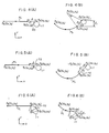
- Fig. 4 is an explanatory view for a case where a tool path (referred to as a "retraction path") lies on an extension of a final machining pass
- Fig. 5 is an explanatory view for a case where a retraction path lies on a tangent to a final machining pass
- Fig. 6 is an explanatory view for a case where a retraction path lies on a tangent circle to a final machining pass
- Figs. 7 through 11 are explanatory views for describing NC data creation processing according to the present invention
- Fig.12 is a block diagram of an embodiment in which the present invention is applied to the creation of NC data
- Fig. 13 is a flowchart of processing for the same
- Fig. 14 is a block diagram for a case where the present invention is applied to numerical control.
- the letter of the alphabet "L” is an address word specifying a distance l 1 shown in Figs. 1 through 6,
- the letters of the alphabet "X”, "Y” are address words specifying axial components (x ,y ) of the starting point P s shown in Figs. 1 through 3, and axial components (x e ,y e ) of the end point P e shown in Figs. 4 through 6, respectively
- the letter of the alphabet " R " is an address word specifying a radius r of the tangential circle shown in Figs. 3 through 6
- the letter of the alphabet "A” is an address word indicating an angle a shown in Figs. 4 and 6
- the letter of the alphabet "F” is an address word for designating feedrate.
- NC data specifying the initial pass or final pass of a machining path are used to calculate the positional coordinates of an approach completion point or tool retraction starting point, as well as data specifying a tool path (approach path) from the approach completion point to the machining starting point, or a tool path (retraction path) from a machining completion point to the tool retraction starting point.
- NC data specifying the approach path and retraction path are created by using the aforementioned calculated data, and if the data indicated by (A), (B) or (C) is substituted for the created NC data, then NC data having an ordinary format will be created. It should be noted that an arrangement is possible wherein the data indicated by (A), (B), (C) is applied directly to an NC apparatus, ordinary NC data are created within the NC apparatus, and NC processing is performed using the NC data created.
- NC data specifying tool paths (approach paths and retraction paths) for cases where the data (A), (B) or (C) are given.
- the given data specifying the tool path shown in Fig. 1(A) will be TlLl 1 Xx S Yy S Ff 1 ; (see Fig. 7).
- "G00” is a G-function instruction for positioning, with movement from a reference point to the approach completion point P a being designated by the first block.
- "G01” is a G-function instruction for linear cutting, with movement from the approach completion point P a to a machining starting point P s at a rate f l being designated by the second block.
- the foregoing is for a case where the distance l 1 is given. If the axial components (x 1 ,y 1 ) from the starting point P S to the approach completion point P a are given, then we will have the following:
- NC data indicative of the first machining pass PF which is a circular arc, are given in the form: Xx e Yy e I-iJj ;
- NC data takes on the form:
- G02 is a G-function instruction for circular cutting in the clockwise direction.
- Tool movement from a reference point to the approach completion point is designated by the first block.
- Movement at a rate f 1 along the circular arc from the approach completion point P a to the machining starting point P s is designated by the second block.
- NC data are created exactly as in case (1).
- the given data specifying the tool path shown in Fig. 2(B) will be T4l 1 Xx s Yy s Ff 1 ; (see Fig. 9).
- NC data indicative of the first machining pass PF which is a circular arc
- (x ,y ) are the coordinate values of the end point P
- (-i,j) are incremental values from the starting point P s of the circular arc to the center P c of the circular arc.
- the slope m 1 of a straight line L N is expressed by the following, using i, j:
- the slope m 2 of the tangent TS to the first machining pass PF at the starting point P thereof is found in the following manner. Specifically, since the tangent TS intersects the straight line LN, we have: from which we may derive the following:
- NC data take on the following form:
- the given data specifying the tool path shown in Fig. 3(A) will be T5RrAaXx s Yy s Ff 1 ; (see Fig. 10).
- the slope m 1 of the machining pass PF is given by the following, using the starting and end point coordinates of the first machining pass PF, which is a straight line:
- NC data take on the form: wherein: "G03" is a G-function instruction signifying circular arc cutting in the counter-clockwise direction.
- the given data specifying the tool path shown in Fig. 3(B) will be T6RrAaXx s Yy s Ff 1 ; (see Fig. 11).
- the coordinate values (x c ',y c ') of the center P c ' of the tangent circle TC are expressed by the set of Eqs. (18) [where cos ⁇ , sin0 are given by Eq. (24).
- the coorinate values x , y a of the approach completion point P a along the respective axes are expressed by Eqs. (19), (20), respectively.
- the NC data take on the following form: wherein i', j' are given by Eqs. (21), (22), respectively.
- NC data indicative of tool paths (approach paths) from the approach completion point P a to the starting point P s of the first machining pass PF have been described in connection with (1) through (6) above.
- the method is substantially the same for the creation of NC data indicative of the retraction tool paths of Figs. 4(A), (B) through Figs. 6(A), (B), with the only difference being the tool travelling direction.
- the following data are given:
- NC data indicative of a retraction path entails substituting x e , y e for x s , y in E q s. (1) through (24), and substituting the starting point coordinates x s , y of the final pass for x , y e in Eqs. (1) through (24). Then, the coordinate values of the retraction starting point P a are found from Eqs. (1) through (24). This is followed by creating NC data for moving the tool from the machining completion point P e to the tool retraction starting point P a at the rate f l , and NC data from moving the tool from the tool retraction starting point P a to the reference point in the rapid traverse mode.
- Fig. 12 is a block diagram of an embodiment for a case where the present invention is applied to an NC data creation apparatus
- Fig. 13 is a flowchart of the associated processing.
- the first step is to successively enter the data necessary to create NC data for a machining tool path.
- the data are entered from a data input unit 101 (such as a keyboard or display).
- Machining path NC data are created under the control of a control program stored in a ROM 102, and the data are stored in a RAM 103.
- data specifying an approach path from an approach completion point to a machining starting point are entered from the data input unit 101 using the format indicated by (A), (B) or (C) shown above.
- a processor 104 which is placed under the control of the control program, discriminates the approach path pattern (which decision is rendered based on the numerical value following the letter of the alphabet "T") and, on the basis of the approach path pattern, executes prescribed calculations from among Eqs. (1) through (24) to create the NC data for the approach.
- the processor 104 arrays the data just ahead of the NC data for the machining path.
- the processor 104 creates NC data indicative of the approach path and, through similar processing, NC data for the retraction path.
- the processor 104 then arrays the retraction path NC data at the end of the machining path data, thereby completing the creation of all NC data. All NC data are stored in the RAM 103.
- NC data are delivered as an output to an external storage medium via a tape puncher 105 or magnetic tape unit 106. This signifies the end of processing.
- Fig. 14 is a block diagram of an embodiment for case where the tool path determination method of the present invention is applied to a numerical control apparatus.
- An NC tape 201 stores machining program data.
- the machining program data comprises the approach path data indicated by (A) through (C) above, NC data specifying a machining path, and the retraction path data indicated by (A) through (C).
- a letter of the alphabet e.g., "P" replaces the letter of the alphabet "T” in the format data (A) through (C).
- a numerical control unit 203 When operation is started by an operator's panel 202, a numerical control unit 203 causes an NC tape reader 204 to reach one block of NC data and stores the NC data in an input memory 205.
- the numerical control unit 203 decodes the NC data stored in the input memory 205 and checks whether the letter of the alphabet "P" is contained in the NC data.
- the numerical control unit 203 applies the instruction to a machine tool 207 through a magnetics circuit 206.
- the numerical control unit 203 executes path processing, described below.
- the numerical control unit 203 applies a point calculation start command to an approach/retraction path calculating unit 208.
- the numerical control unit 203 executes path control, which will now be described with regard to a straight line.
- the numerical control unit 203 obtains incremental values X i , Y i , Z. along the respective axes based on a target position (X e , Y e' Z e ) stored in the input memory 205, and a current position (X , Y a , Z a ) stored in a memory 209.
- the numerical control unit obtained velocity components F x , F y , F z along the respective axes from the following equations:
- travelling distances ⁇ X , ⁇ Y , ⁇ Z are delivered to a pulse distributor 210 regularly at the time interval d T.
- the pulse distributor 210 performs a pulse distribution computation simultaneously along the three axes to generate distributed pulses X p , Y p , Z p .
- Theses pulses are applied to respective servo circuits 211X, 211Y, 211Z for the respective axes, thus to rotate servomotors 212X, 212Y, 212Z.
- the tool is thus moved, relative to the workpiece, toward the target position.
- the numerical control unit 203 in accordance with the following expressions, updates the current positions X , Y a , Z a along the respective axes regularly at the time interval ⁇ T sec, which positions have been stored in the memory 209:
- the numerical control unit 203 updates remaining travelling distances X , Y , Z (the initial values whereof are the incremental values X., Y i , Z i , respectively) every ⁇ T sec, these travelling distances having been stored in the memory 209:
- the numerical control unit 203 causes the NC data reader 204 to read in the next item of NC data.
- the numerical control unit 203 causes the NC data reader 204 to read the NC data of the initial pass, stores the data in the input memory 205, and applies a computation start command CSI to the approach/retraction path calculating unit 208.
- the approach/retraction path calculating unit 208 checks the numerical value following the letter of the alphabet "P", which numerical value has been stored in the input memory 205, identifies the path pattern specified by the input data, calculates data specifying the approach completion point and approach path, as well as data specifying the retraction starting point and retraction path, and applies the results of the computations to the numerical control unit 203. These computations are performed using prescribed arithmetic expressions among the Eqs. (1) through (24), the formula depending upon the aforementioned identifying operation.
- the numerical control unit 203 obtains incremental values along the respective axes. If the path is an approach path, these values are found by using positional data indicative of the approach completion point contained in the results of the computations, as well as current position data (X , Y , Z ) stored in the memory 209. Thereafter, the above-described path processing is executed using a rapid-traverse rate F o (already known) and the aforementioned incremental values, thus to move the tool to the approach completion point in the rapid-traverse mode.
- F o rapid-traverse rate
- the numerical control unit 203 performs path processing using the data specifying the approach path, and positions the tool at the starting point of the initial pass at the cutting rate f l . If the approach path is a straight line, path processing is performed as described above. If the approach path is a circular arc, then circular arc path processing is performed.
- the numerical control unit repeats the above-described processing using the N C data indicative of the initial machining pass. These data have already been read and stored in the input memory 205. It should be noted that the processing for a retraction path is similar to that for the approach path.
- the present invention as described in detail above is not limited to the embodiment but can be modified in various ways within the scope of the claims.
- the data formats are not limited to (A) through (C), for a vector (components along the respective axes) can be given instead of the distance Q 1 , and an angle 1 1 can be given instead of the angle a with regard to the patterns shown in Fig. 3.
- the tool mentioned in the foregoing description is assumed to cover the wire electrode used in a wire-cut electric discharge machine.
- merely entering simple data enables the creation of NC data for smoothly connecting an approach path to an initial machining pass, as well as data for smoothly connecting a retraction path to a final machining pass. Since the arrangement is such that a tool path can be smoothly connected to an initial or final machining pass, excellent NC machining can be performed without a finished surface developing checkering or the like.
- the present invention is therefore well-suited for application to an NC data creation apparatus or NC apparatus.
Landscapes
- Physics & Mathematics (AREA)
- Engineering & Computer Science (AREA)
- Geometry (AREA)
- Human Computer Interaction (AREA)
- Manufacturing & Machinery (AREA)
- General Physics & Mathematics (AREA)
- Automation & Control Theory (AREA)
- Numerical Control (AREA)
- Automatic Control Of Machine Tools (AREA)
Abstract
Un procédé de détermination du cheminement d'un outil est utilisé pour déterminer le cheminement d'un outil (ES) depuis un point d'approche (Pa) jusqu'à un point de départ (Ps) d'un premier cheminement d'usinage (PF). Le procédé comprend une première étape consistant à introduire des données ($(1,3)$1, xs, ys; a, xs, ys) spécifiant un modèle de cheminement d'outil prédéterminé parmi une pluralité de modèles de cheminement d'outil et spécifiant également le point d'approche (Pa); une deuxième étape consistant à calculer les coordonnées (xa, ya) de la position du point d'approche (Pa) en utilisant une expression opérationnelle correspondant au modèle de cheminement d'outil spécifié et les données spécifiant le point d'approche; une troisième étape consistant à déterminer le cheminement d'outil (ES) depuis le point d'approche (Pa) jusqu'au point de départ (Ps) du cheminement d'usinage (PF), sur la base du point d'approche et du modèle de cheminement spécifié.
Applications Claiming Priority (2)
| Application Number | Priority Date | Filing Date | Title |
|---|---|---|---|
| JP25186/83 | 1983-02-17 | ||
| JP58025186A JPS59152047A (ja) | 1983-02-17 | 1983-02-17 | 工具通路決定方法 |
Publications (2)
| Publication Number | Publication Date |
|---|---|
| EP0139009A1 true EP0139009A1 (fr) | 1985-05-02 |
| EP0139009A4 EP0139009A4 (fr) | 1987-03-12 |
Family
ID=12158943
Family Applications (1)
| Application Number | Title | Priority Date | Filing Date |
|---|---|---|---|
| EP19840900755 Withdrawn EP0139009A4 (fr) | 1983-02-17 | 1984-02-14 | Procede de determination du cheminement d'un outil. |
Country Status (3)
| Country | Link |
|---|---|
| EP (1) | EP0139009A4 (fr) |
| JP (1) | JPS59152047A (fr) |
| WO (1) | WO1984003243A1 (fr) |
Cited By (2)
| Publication number | Priority date | Publication date | Assignee | Title |
|---|---|---|---|---|
| GB2207776A (en) * | 1987-06-19 | 1989-02-08 | Mitsubishi Electric Corp | Numerical control apparatus |
| EP0766157A3 (fr) * | 1989-03-22 | 1997-06-04 | Vickers Esd Inc | Améliorations concernant la correction dynamique des erreurs dues au servomécanisme dans un système à commande numérique par ordinateur et cycle fixe utilisant celles-ci |
Families Citing this family (3)
| Publication number | Priority date | Publication date | Assignee | Title |
|---|---|---|---|---|
| JPS6085812A (ja) * | 1983-10-15 | 1985-05-15 | Fanuc Ltd | 領域加工におけるアプロ−チ方法 |
| KR930011214B1 (ko) * | 1988-01-20 | 1993-11-29 | 미쓰비시전기 주식회사 | 절삭공구에 의한 날선단반경 보정형상의 작성방법 |
| CN115534133B (zh) * | 2022-11-11 | 2024-08-23 | 泉州市大鲨鱼机械科技有限公司 | 绳锯切割装置及切割方法 |
Family Cites Families (5)
| Publication number | Priority date | Publication date | Assignee | Title |
|---|---|---|---|---|
| US4238550A (en) * | 1979-02-05 | 1980-12-09 | Equipment Manufacturing, Inc. | Dunnage bar and method of making it |
| JPS5796752A (en) * | 1980-12-03 | 1982-06-16 | Daihatsu Motor Co Ltd | Method of controlling rough working in nc lathe |
| JPS6232750Y2 (fr) * | 1980-12-19 | 1987-08-21 | ||
| JPS57205048A (en) * | 1981-06-12 | 1982-12-16 | Yamazaki Mazak Corp | Numerical control machine tool |
| NL8203413A (nl) * | 1982-09-01 | 1984-04-02 | Philips Nv | Werkwijze voor het verwijderen van en het terugbrengen naar een werkstuk van een gereedschap bij het verspanend bewerken van dat werkstuk door een numeriek bestuurde gereedschapsmachine en numeriek bestuurde gereedschapsmachine voor het uitvoeren van de werkwijze. |
-
1983
- 1983-02-17 JP JP58025186A patent/JPS59152047A/ja active Pending
-
1984
- 1984-02-14 WO PCT/JP1984/000044 patent/WO1984003243A1/fr not_active Ceased
- 1984-02-14 EP EP19840900755 patent/EP0139009A4/fr not_active Withdrawn
Cited By (4)
| Publication number | Priority date | Publication date | Assignee | Title |
|---|---|---|---|---|
| GB2207776A (en) * | 1987-06-19 | 1989-02-08 | Mitsubishi Electric Corp | Numerical control apparatus |
| US4926338A (en) * | 1987-06-19 | 1990-05-15 | Mitsubishi Denki Kabushiki Kaisha | Numerical control apparatus |
| GB2207776B (en) * | 1987-06-19 | 1992-02-26 | Mitsubishi Electric Corp | Numerical control apparatus |
| EP0766157A3 (fr) * | 1989-03-22 | 1997-06-04 | Vickers Esd Inc | Améliorations concernant la correction dynamique des erreurs dues au servomécanisme dans un système à commande numérique par ordinateur et cycle fixe utilisant celles-ci |
Also Published As
| Publication number | Publication date |
|---|---|
| EP0139009A4 (fr) | 1987-03-12 |
| JPS59152047A (ja) | 1984-08-30 |
| WO1984003243A1 (fr) | 1984-08-30 |
Similar Documents
| Publication | Publication Date | Title |
|---|---|---|
| KR880002560B1 (ko) | 수치 제어방식 | |
| KR850000328B1 (ko) | 수치 제어방법 | |
| EP0098044B1 (fr) | Machine-outil à commande numérique faisant des mesures intermédiaires | |
| WO1989006174A1 (fr) | Dispositif laser pour l'usinage tridimensionnel | |
| EP0077177B1 (fr) | Méthode et dispositif pour la commande numérique | |
| EP0127688B1 (fr) | Procede de commande de profilage | |
| EP0137047B1 (fr) | Procede de determination du cheminement tridimensionnel d'un outil | |
| US4739489A (en) | Area cutting method | |
| EP0160096A1 (fr) | Procede d'approche dans l'usinage de surfaces | |
| EP0068029A1 (fr) | Procede de commande d'usinage par electro-erosion a fil | |
| EP0276312B1 (fr) | Procede pour calculer un vecteur normal | |
| EP0139009A1 (fr) | Procede de determination du cheminement d'un outil | |
| EP0420985B1 (fr) | Systeme de regulation de vitesse par interpolation de developpante | |
| EP0529239B1 (fr) | Unité de commande numérique avec commande d'un compteur de position et indicateur | |
| EP0364600B1 (fr) | Procede d'usinage de vis rondes | |
| EP0161321B1 (fr) | Procede d'usinage pour machine-outil | |
| EP0151187B1 (fr) | Procede permettant de specifier une courbe tridimensionnelle | |
| HK1004296B (en) | Numerical control unit with position counter control and display | |
| EP1457852B1 (fr) | Procédé et dispositif pour éditer un programme pour l'usinage de matrices | |
| GB2043957A (en) | Numerical Control System | |
| EP0071378A1 (fr) | Méthode et appareil pour la commande numérique | |
| EP0231388B1 (fr) | Procede d'usinage de surface | |
| EP0451795A2 (fr) | Unité de commande numérique avec correction pour l'erreur de décalage | |
| KR910007274B1 (ko) | 면 가공방법 | |
| US5347461A (en) | Tool travel path creating method |
Legal Events
| Date | Code | Title | Description |
|---|---|---|---|
| PUAI | Public reference made under article 153(3) epc to a published international application that has entered the european phase |
Free format text: ORIGINAL CODE: 0009012 |
|
| 17P | Request for examination filed |
Effective date: 19841029 |
|
| AK | Designated contracting states |
Designated state(s): DE FR GB |
|
| A4 | Supplementary search report drawn up and despatched |
Effective date: 19870312 |
|
| STAA | Information on the status of an ep patent application or granted ep patent |
Free format text: STATUS: THE APPLICATION HAS BEEN WITHDRAWN |
|
| 18W | Application withdrawn |
Withdrawal date: 19870610 |
|
| RIN1 | Information on inventor provided before grant (corrected) |
Inventor name: SEKI, MASAKI Inventor name: KISHI, HAJIMU |