EP0139151B1 - Seiltrommel - Google Patents
Seiltrommel Download PDFInfo
- Publication number
- EP0139151B1 EP0139151B1 EP84109874A EP84109874A EP0139151B1 EP 0139151 B1 EP0139151 B1 EP 0139151B1 EP 84109874 A EP84109874 A EP 84109874A EP 84109874 A EP84109874 A EP 84109874A EP 0139151 B1 EP0139151 B1 EP 0139151B1
- Authority
- EP
- European Patent Office
- Prior art keywords
- cable
- cable drum
- slot
- projections
- rope
- Prior art date
- Legal status (The legal status is an assumption and is not a legal conclusion. Google has not performed a legal analysis and makes no representation as to the accuracy of the status listed.)
- Expired
Links
Images
Classifications
-
- B—PERFORMING OPERATIONS; TRANSPORTING
- B66—HOISTING; LIFTING; HAULING
- B66D—CAPSTANS; WINCHES; TACKLES, e.g. PULLEY BLOCKS; HOISTS
- B66D1/00—Rope, cable, or chain winding mechanisms; Capstans
-
- B—PERFORMING OPERATIONS; TRANSPORTING
- B60—VEHICLES IN GENERAL
- B60S—SERVICING, CLEANING, REPAIRING, SUPPORTING, LIFTING, OR MANOEUVRING OF VEHICLES, NOT OTHERWISE PROVIDED FOR
- B60S5/00—Servicing, maintaining, repairing, or refitting of vehicles
-
- B—PERFORMING OPERATIONS; TRANSPORTING
- B66—HOISTING; LIFTING; HAULING
- B66D—CAPSTANS; WINCHES; TACKLES, e.g. PULLEY BLOCKS; HOISTS
- B66D1/00—Rope, cable, or chain winding mechanisms; Capstans
- B66D1/28—Other constructional details
- B66D1/30—Rope, cable, or chain drums or barrels
- B66D1/34—Attachment of ropes or cables to drums or barrels
Definitions
- the invention relates to a cable drum for the spare wheel winch of a commercial vehicle, such as a truck or an omnibus.
- Such a cable winch forms a rarely used auxiliary unit and is therefore only designed for relatively few cases of use for cost reasons.
- a pipe socket is therefore used as the cable drum, on which the end of the cable is riveted or passed through a bore and wedged.
- fastening leads to a crushing or kinking of the rope, which can then tear at the point in question even after relatively few uses.
- the invention has for its object to provide a cheap and easy to assemble and manufacture rope drum, which nevertheless allows such a fastening of a rope that this rope is not overloaded at the attachment point even when it is completely unwound should be.
- the rope drum is made of plastic, at least on its outer circumference, but preferably entirely, the bracket for fastening the rope being formed from two projections formed side by side at one end of the rope drum, which form a tangential receptacle for the rope between them. It is only necessary to attach a thickening at the end of the rope, for example in the form of a clamped or soldered sleeve, the width of which is greater than the distance between the two projections. The rope then only has to be inserted between the projections and thus runs tangentially onto the circumference of the rope drum. The rope is no longer kinked or crushed, so that it can be unwound to the end.
- the rope drum according to the invention thus not only enables the full rope length to be used, but also does not require a separate operation to produce it, since the projections are also molded on during the shaping of the plastic rope drum. Finally, the assembly of the cable winch is also greatly simplified, since in the cable drum according to the invention the cable simply has to be inserted between the projections and, if need be, prevented from slipping out there by a simple measure.
- the two projections are arranged in such a way that the receptacle formed between them not only runs tangentially, but is also slightly inclined in the axial direction of the cable drum, in order to allow the cable to be led off completely without kinks.
- the two projections generally lie next to one another approximately in the axial direction, wherein a slight inclination of the receptacle formed between them to the circumferential direction should also be included.
- the inner of the two projections is designed according to the invention as a circumferential flange, which limits the section of the cable drum designed for winding the cable towards the holder.
- a gap is formed in this peripheral flange near the receptacle, which gap is suitable for passing the rope through. It is thus prevented that, when the rope is being wound up, it runs away directly at the receptacle over the part inserted there and presses it approximately laterally against one of the projections, which could otherwise lead to a kink.
- the receptacle is formed by a slot, the width of which corresponds to that of the rope and the bottom of which is rounded in accordance with the radius of the rope. At one end of the slot, it is widened to form a partially cylindrical seat, which is designed in such a way that it can accommodate a cylindrical nipple attached to the end of the rope, preferably with a slight press fit.
- a pin penetrating the two projections is arranged transversely to the course of the rope, with a distance from the bottom of the slot that is larger than the diameter of the rope, but smaller than the distance of the outer contour of the cylindrical nipple mentioned from the bottom of the slot.
- This pin is located just behind the nipple and is an additional safeguard to prevent the rope from slipping.
- this pin it is advantageous to design this pin as a grooved pin and to drive it into corresponding transverse bores in the projections, since it is possible with this configuration is to use a ready-made rope with end thimble at one end and end nipple at the other end, insert it into the slot or seat and then hammer in or press in the notch pin.
- the invention relates not only to the rope drum described, but also to the arrangement formed from the rope drum and rope
- a spare wheel winch which has a plastic cable drum.
- One end A of which is rotatably supported in a bearing plate 2 such that its axial movement in the direction of the bearing plate 2 is prevented.
- an annular collar In front of the other end of the cable drum 1, an annular collar is arranged, which is supported on the end wall of a gear housing 6. In this a worm 7 is mounted, which meshes with a half worm wheel 4, which is attached to the adjacent end of the cable drum 1.
- the cable drum 1 and the worm 7 are designed as hollow parts and, like the half-worm wheel 4, are formed entirely from plastic.
- the cable drum 1 has an area for winding a cable 9, which is delimited towards the gear housing 6 by the said collar and towards the bearing plate 3 by a peripheral flange 8, the diameter of which corresponds approximately to that of the collar.
- a projection 5 is formed on the outer circumference of the cable drum 1, the radial height of which corresponds to that of the circumferential flange 8.
- a slot 10 is cut out between the projection 5 and the circumferential flange 8, the width of which corresponds to the diameter of the cable 9 or is slightly smaller. This slot 10 is rounded on its radially inner bottom.
- the peripheral flange 8 In the winding direction of the rope 9 adjacent to the projection 10, the peripheral flange 8 has a gap 15, through which (seen in Fig. 1) the rope 9, which is clamped at its end in the slot 10, without undue bending in the Winding the rope 9 certain area of the rope drum 1 can be brought about.
- the slot 10 is cylindrically widened towards that end which faces away from the gap 15, the central axis of this cylinder coinciding with the center of the rope 9 running on the slot.
- This cylindrical extension forms a seat 12, which is set up to accommodate an end nipple 11, which is attached to the free end of the cable 9.
- the projection 5 and the peripheral flange 8 are pierced, the direction of the bore being parallel to the central axis of the cable drum 1.
- a notch pin 13 is hammered into this bore, which ends with the surfaces of the projection 5 and the peripheral flange 8 facing away from the slot 10.
- the position of the pin 13 is selected such that it does not lie against the rope 9, but protrudes into the contour of the nipple 11, so that it prevents the nipple 11 from being pulled out in the tangential direction, even if it does would remove the plastic of the rope drum by a particularly violent pressure.
Landscapes
- Engineering & Computer Science (AREA)
- Mechanical Engineering (AREA)
- Storage Of Web-Like Or Filamentary Materials (AREA)
- Rolls And Other Rotary Bodies (AREA)
Description
- Die Erfindung betrifft eine Seiltrommel für die Reserveradwinde eines Nutzfahrzeuges, etwa eines Lkw's oder eines Omnibusses.
- Eine solche Seilwinde bildet ein nur selten benutztes Nebenaggregat und wird deshalb aus Kostengründen auch nur für verhältnismässig wenige Benutzungsfälle ausgelegt. Als Seiltrommel verwendet man daher einen Rohrstutzen, an welchem das Ende des Seiles angenietet oder durch eine Bohrung durchgeführt und verkeilt ist. Eine solche Befestigung führt allerdings zu einer Quetschung oder Abknickung des Seiles, das an der betreffenden Stelle dann auch bereits nach verhältnismässig wenig Benutzungsfällen reissen kann.
- Ausserdem ist es erforderlich, um die Belastung an der Befestigungsstelle des Seiles auf ein Mindestmass zu reduzieren, die Seiltrommel so auszulegen, dass nach Abwickeln der vollen Nutzlänge des Seiles noch ein längeres Seilende auf der Trommel aufgewickelt bleibt. Dies vergrössert aber die Baugrösse der Seiltrommel.
- Nach der US-A-2 892 598 ist eine Seiltrommel mit einer im Aussenflansch angebrachten Seilendenhalterung bekannt. Die Halterung ist aufwendig in der Herstellung, wie auch das Einfädeln des Seilendes in die Halterung umständlich ist.
- Ausgehend von diesem Stand der Technik liegt der Erfindung die Aufgabe zugrunde, eine billig und einfach zu montierende und herzustellende Seiltrommel zu schaffen, welche dennoch eine solche Befestigung eines Seiles zulässt, dass dieses Seil an der Befestigungsstelle selbst dann nicht überlastet wird, wenn es ganz abgewickelt werden sollte.
- Diese Aufgabe wird erfindungsgemäss durch die Merkmale des Anspruchs 1 gelöst. Hierbei ist die Seiltrommel aus Kunststoff geformt, und zwar mindestens an ihrem Aussenumfang, bevorzugt jedoch ganz, wobei die Halterung zur Befestigung des Seiles aus zwei am einen Ende der Seiltrommel nebeneinanderliegend angeformten Vorsprüngen gebildet ist, die zwischeneinander eine tangentiale Aufnahme für das Seil bilden. Es ist lediglich am Seilende eine Verdickung anzubringen, etwa in Form einer aufgeklemmten oder aufgelöteten Muffe, deren Breite grösser ist als der Abstand zwischen den beiden Vorsprüngen. Das Seil muss dann lediglich zwischen die Vorsprünge eingelegt werden und läuft somit tangential auf den Umfang der Seiltrommel auf. Das Seil wird somit nicht mehr geknickt oder gequetscht, so dass es bis ganz zum Ende abgewickelt werden kann.
- Die erfindungsgemässe Seiltrommel ermöglicht somit nicht nur die Nutzung der vollen Seillänge, sondern bedarf zur Herstellung auch keines gesonderten Arbeitsganges, da während der Formgebung der Kunststoff-Seiltrommel im gleichen Arbeitsgang auch die Vorsprünge mit angeformt werden. Schliesslich ist auch der Zusammenbau der Seilwinde stark vereinfacht, da bei der erfindungsgemässen Seiltrommel das Seil einfach nur zwischen die Vorsprünge eingelegt und dort allenfalls noch durch eine einfache Massnahme am Herausrutschen gehindert zu werden braucht.
- Es ist besonders von Vorteil, die beiden Vorsprünge derart anzuordnen, dass die zwischen ihnen gebildete Aufnahme nicht nur tangential verläuft, sondern auch in Achsrichtung der Seiltrommel leicht geneigt ist, um eine völlig knickfreie Ableitung des Seiles zu gestatten. Gemäss einer Ausgestaltung der Erfindung ist es aber von Vorteil, dass die beiden Vosprünge ganz allgemein etwa in Achsrichtung nebeneinanderliegen, wobei auch eine leichte Neigung der zwischen ihnen gebildeten Aufnahme zur Umfangsrichtung mit umfasst sein soll. Der innenliegende der beiden Vorsprünge ist erfindungsgemäss als Umfangsflansch ausgebildet, der den zum Aufwickeln des Seiles ausgebildeten Abschnitt der Seiltrommel zur Halterung hin begrenzt. In diesen Umfangsflansch ist nahe der Aufnahme eine Lücke ausgebildet, die zum Durchführen des Seiles geeignet ist. Es wird somit verhindert, dass beim Aufwickeln des Seiles dieses unmittelbar an der Aufnahme über das dort eingelegte Teil wegläuft und es etwa seitlich gegen einen der Vorsprünge andrückt, was sonst zu einer Knickstelle führen könnte.
- Die Aufnahme ist gemäss einer weiteren Ausgestaltung der Erfindung von einem Schlitz gebildet, dessen Breite jener des Seiles entspricht und dessen Boden entsprechend dem Radius des Seiles ausgerundet ist. Am einen Ende des Schlitzes ist dieser zum einem teilzylindrischen Sitz aufgeweitet, der so ausgestaltet ist, dass er einen zylindrischen, am Seilende befestigten Nippel passend und bevorzugt mit leichtem Presssitz aufnehmen kann.
- Gemäss einer weiteren Ausgestaltung der Erfindung ist quer zum Verlauf des Seiles ein die beiden Vorsprünge durchdringender Stift angeordnet, und zwar mit einem Abstand zum Boden des Schlitzes, der grösser ist als der Durchmesser des Seiles, aber kleiner als der Abstand der Aussenkontur des genannten zylindrischen Nippels vom Boden des Schlitzes. Dieser Stift befindet sich kurz hinter dem Nippel und stellt eine zusätzliche Sicherung dar, um das Durchrutschen des Seiles zu verhindern.
- Es ist dem Grunde nach möglich, den Stift bereits beim Formungsvorgang der Kunststoff-Seiltrommel mit einzuformen, es ist aber gemäss einer Ausgestaltung der Erfindung von Vorteil, diesen Stift als Kerbstift auszubilden und in entsprechende Querbohrungen in den Vorsprüngen einzuschlagen, da es bei dieser Ausgestaltung möglich ist, ein bereits fertig hergestelltes, mit Endkausche am einen Ende und Endnippel am anderen Ende versehenes Seil zu verwenden, in den Schlitz bzw. den Sitz einzulegen und anschliessend den Kerbstift einzuschlagen oder einzudrükken.
- Die Erfindung bezieht sich nicht nur auf die beschriebene Seiltrommel, sondern auch auf die aus Seiltrommel und Seil gebildete Anordnung
- sowie auf eine die genannte Anordnung enthaltende Seilwinde.
- Der Gegenstand der Erfindung ist anhand der beigefügten, schematischen Zeichnung noch näher erläutert. In dieser zeigt:
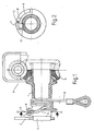
- Fig. 1 eine Reserveradwinde in teilweise geschnittener Seitenansicht, und
- Fig. 2 den Schnitt längs 11-11 durch die Seiltrommel der Reserveradwinde der Fig. 1.
- In Fig. 1 ist eine Reserveradwinde gezeigt, die eine Kunststoff-Seiltrommel aufweist. Deren eines Ende A ist in einem Lagerblech 2 drehbar derart abgestützt, dass ihre Axialbewegung in Richtung zum Lagerblech 2 verhindert ist.
- Vor dem anderen Ende der Seiltrommel 1 ist ein Ringbund angeordnet, der sich auf der Stirnwand eines Getriebegehäuses 6 abstützt. In diesem ist eine Schnecke 7 gelagert, die mit einem Halbschneckenrad 4 kämmt, das am benachbarten Ende der Seiltrommel 1 befestigt ist.
- Die Seiltrommel 1 und die Schnecke 7 sind als Hohlteile ausgebildet und sind, wie auch das Halbschneckenrad 4, ganz aus Kunststoff geformt.
- Die Seiltrommel 1 weist einen Bereich zum Aufwickeln eines Seiles 9 auf, der zum Getriebegehäuse 6 hin durch den genannten Ringbund und zum Lagerblech 3 hin durch einen Umfangsflansch 8 begrenzt wird, dessen Durchmesser etwa jenem des Ringbundes entspricht.
- Zwischen dem Umfangsflansch 8 und dem Lagerblech 2 ist ein Vorsprung 5 am Aussenumfang der Seiltrommel 1 angeformt, dessen radiale Höhe jener des Umfangsflansches 8 entspricht.
- Zwischen Vorsprung 5 und Umfangsflansch 8 ist ein Schlitz 10 ausgespart, dessen Breite dem Durchmesser des Seiles 9 entspricht oder geringfügig kleiner ist. Dieser Schlitz 10 ist an seinem radial innenliegenden Boden ausgerundet.
- In Aufwickelrichtung des Seiles 9 an den Vorsprung 10 angrenzend, weist der Umfangsflansch 8 eine Lücke 15 auf, durch welche (in Fig. 1 ersichtlich) das Seil 9, das mit seinem Ende in den Schlitz 10 eingeklemmt ist, ohne unzulässige Biegung in den zum Aufwickeln des Seiles 9 bestimmten Bereich der Seiltrommel 1 herbeigeführt werden kann.
- Der Schlitz 10 ist zu jenem Ende hin, das von der Lücke 15 abgewandt ist, zylindrisch ausgeweitet, wobei die Mittelachse dieses Zylinders mit dem Mittelpunkt des am Schlitz auflaufenden Seiles 9 zusammenfällt. Diese zylindrische Ausweitung bildet einen Sitz 12, der zur passenden Aufnahme eines Endnippels 11 eingerichtet ist, der am freien Ende des Seiles 9 befestigt ist.
- An jenem Abschnitt des Schlitzes 10, der nicht den Sitz 12 aufweist, und diesem benachbart, sind der Vorsprung 5 und der Umfangsflansch 8 durchbohrt, wobei die Richtung der Bohrung parallel zur Mittelachse der Seiltrommel 1 verläuft. In dieser Bohrung ist ein Kerbstift 13 eingeschlagen, der mit den dem Schlitz 10 abgewandten Oberflächen des Vorsprunges 5 und des Umfangsflansches 8 abschliesst.
- Wie aus Fig. 2 ersichtlich, ist die Lage des Stiftes 13 derart gewählt, dass dieser zwar nicht gegen das Seil 9 anliegt, aber in die Kontur des Nippels 11 hineinragt, so dass er das Ausziehen des Nippels 11 in Tangentialrichtung verhindert, auch wenn dieser durch einen besonders heftigen Druck den Kunststoff der Seiltrommel abtragen würde.
Claims (6)
Priority Applications (1)
| Application Number | Priority Date | Filing Date | Title |
|---|---|---|---|
| AT84109874T ATE37699T1 (de) | 1983-08-24 | 1984-08-18 | Seiltrommel. |
Applications Claiming Priority (2)
| Application Number | Priority Date | Filing Date | Title |
|---|---|---|---|
| DE19838324289U DE8324289U1 (de) | 1983-08-24 | 1983-08-24 | Seiltrommel |
| DE8324289U | 1983-08-24 |
Publications (3)
| Publication Number | Publication Date |
|---|---|
| EP0139151A2 EP0139151A2 (de) | 1985-05-02 |
| EP0139151A3 EP0139151A3 (en) | 1987-01-07 |
| EP0139151B1 true EP0139151B1 (de) | 1988-10-05 |
Family
ID=6756414
Family Applications (1)
| Application Number | Title | Priority Date | Filing Date |
|---|---|---|---|
| EP84109874A Expired EP0139151B1 (de) | 1983-08-24 | 1984-08-18 | Seiltrommel |
Country Status (3)
| Country | Link |
|---|---|
| EP (1) | EP0139151B1 (de) |
| AT (1) | ATE37699T1 (de) |
| DE (2) | DE8324289U1 (de) |
Families Citing this family (1)
| Publication number | Priority date | Publication date | Assignee | Title |
|---|---|---|---|---|
| US12202714B2 (en) | 2020-03-23 | 2025-01-21 | Konecranes Global Corporation | Rope drum of rope hoist and fastening device of hoisting rope |
Family Cites Families (3)
| Publication number | Priority date | Publication date | Assignee | Title |
|---|---|---|---|---|
| US1461052A (en) * | 1920-08-27 | 1923-07-10 | William E Simpson | Hoist |
| US2892598A (en) * | 1956-05-24 | 1959-06-30 | Nat Supply Co | Cable drum grooving |
| DE1184478B (de) * | 1963-12-27 | 1964-12-31 | Hilgers A G | Windentrommel mit einer Ausnehmung im Trommelmantel zum loesbaren Befestigen des aufliegenden Seil- oder Kettenendes |
-
1983
- 1983-08-24 DE DE19838324289U patent/DE8324289U1/de not_active Expired
-
1984
- 1984-08-18 AT AT84109874T patent/ATE37699T1/de active
- 1984-08-18 DE DE8484109874T patent/DE3474436D1/de not_active Expired
- 1984-08-18 EP EP84109874A patent/EP0139151B1/de not_active Expired
Also Published As
| Publication number | Publication date |
|---|---|
| DE8324289U1 (de) | 1983-12-01 |
| EP0139151A3 (en) | 1987-01-07 |
| ATE37699T1 (de) | 1988-10-15 |
| DE3474436D1 (en) | 1988-11-10 |
| EP0139151A2 (de) | 1985-05-02 |
Similar Documents
| Publication | Publication Date | Title |
|---|---|---|
| DE2260790C2 (de) | Schneidkopf für eine Vorrichtung zum Schneiden von Pflanzen | |
| DE91411T1 (de) | Papierrollenhalter mit zentraler papierausgabe. | |
| DE3337344A1 (de) | Tragbare schlauchwickelvorrichtung, insbesondere fuer wagen, caravans, omnibusse, schiffe, balkone und kleine gaerten | |
| EP0758728A1 (de) | Halteelement aus Kunststoff | |
| DE102007034900A1 (de) | Positionserfassungssensor | |
| DE2641272A1 (de) | Rad fuer moebel mit zwei achsgleichen laufrollen | |
| EP0379834A1 (de) | Kupplungsvorrichtung, insbesondere an Apparaten zum Dispergieren | |
| CH682688A5 (de) | Schaftanordnung mit wenigstens einem Kugel- oder Rollenlager. | |
| EP0139151B1 (de) | Seiltrommel | |
| EP0278995A1 (de) | Steckbolzen und Vorrichtung zu seiner Montage | |
| DE4115968C2 (de) | Anordnung zur Befestigung eines Schlauches an einer Hülse | |
| EP0332209A1 (de) | Rohr | |
| DE19508638A1 (de) | Handbrause | |
| DE4232796C2 (de) | Rohrverbindung | |
| DE687212C (de) | Abspannklemme fuer Stahlaluminiumseile | |
| CH227721A (de) | Tube. | |
| DE3244246C2 (de) | ||
| DE29816510U1 (de) | Anschlußdose mit eingesetztem Winkelstück für einen WC-Spülkasten | |
| DE721578C (de) | Riemenverbinder fuer Rund- und Keilriemen | |
| EP1020150A1 (de) | Kleiderbügel | |
| DE8110450U1 (de) | Vorrichtung zur Befestigung einer Welle mit rollenden Lagern in einem zylinderförmigen Rohrstück | |
| DE7508316U (de) | Vorrichtung zum verschrauben eines schlauches mit einer sauerstofflanze | |
| DE20100730U1 (de) | Griff für Möbel u.dgl. | |
| DE3131740A1 (de) | Vorrichtung zur halterung eines koerpers zwischen zwei zueinander parallelen teilen | |
| CH681650A5 (de) |
Legal Events
| Date | Code | Title | Description |
|---|---|---|---|
| PUAI | Public reference made under article 153(3) epc to a published international application that has entered the european phase |
Free format text: ORIGINAL CODE: 0009012 |
|
| AK | Designated contracting states |
Designated state(s): AT DE FR GB IT NL SE |
|
| RAP1 | Party data changed (applicant data changed or rights of an application transferred) |
Owner name: M A N NUTZFAHRZEUGE GMBH |
|
| PUAL | Search report despatched |
Free format text: ORIGINAL CODE: 0009013 |
|
| AK | Designated contracting states |
Kind code of ref document: A3 Designated state(s): AT DE FR GB IT NL SE |
|
| 17P | Request for examination filed |
Effective date: 19870227 |
|
| 17Q | First examination report despatched |
Effective date: 19871022 |
|
| GRAA | (expected) grant |
Free format text: ORIGINAL CODE: 0009210 |
|
| AK | Designated contracting states |
Kind code of ref document: B1 Designated state(s): AT DE FR GB IT NL SE |
|
| REF | Corresponds to: |
Ref document number: 37699 Country of ref document: AT Date of ref document: 19881015 Kind code of ref document: T |
|
| GBT | Gb: translation of ep patent filed (gb section 77(6)(a)/1977) | ||
| REF | Corresponds to: |
Ref document number: 3474436 Country of ref document: DE Date of ref document: 19881110 |
|
| ITF | It: translation for a ep patent filed | ||
| ET | Fr: translation filed | ||
| PLBE | No opposition filed within time limit |
Free format text: ORIGINAL CODE: 0009261 |
|
| STAA | Information on the status of an ep patent application or granted ep patent |
Free format text: STATUS: NO OPPOSITION FILED WITHIN TIME LIMIT |
|
| RAP2 | Party data changed (patent owner data changed or rights of a patent transferred) |
Owner name: MAN NUTZFAHRZEUGE AKTIENGESELLSCHAFT |
|
| 26N | No opposition filed | ||
| NLT2 | Nl: modifications (of names), taken from the european patent patent bulletin |
Owner name: MAN NUTZFAHRZEUGE AKTIENGESELLSCHAFT TE MUENCHEN, |
|
| PGFP | Annual fee paid to national office [announced via postgrant information from national office to epo] |
Ref country code: AT Payment date: 19900706 Year of fee payment: 7 |
|
| PGFP | Annual fee paid to national office [announced via postgrant information from national office to epo] |
Ref country code: SE Payment date: 19900724 Year of fee payment: 7 |
|
| PGFP | Annual fee paid to national office [announced via postgrant information from national office to epo] |
Ref country code: GB Payment date: 19900807 Year of fee payment: 7 |
|
| PGFP | Annual fee paid to national office [announced via postgrant information from national office to epo] |
Ref country code: DE Payment date: 19900823 Year of fee payment: 7 |
|
| PGFP | Annual fee paid to national office [announced via postgrant information from national office to epo] |
Ref country code: FR Payment date: 19900830 Year of fee payment: 7 |
|
| ITTA | It: last paid annual fee | ||
| PGFP | Annual fee paid to national office [announced via postgrant information from national office to epo] |
Ref country code: NL Payment date: 19900831 Year of fee payment: 7 |
|
| PG25 | Lapsed in a contracting state [announced via postgrant information from national office to epo] |
Ref country code: GB Effective date: 19910818 Ref country code: AT Effective date: 19910818 |
|
| PG25 | Lapsed in a contracting state [announced via postgrant information from national office to epo] |
Ref country code: SE Effective date: 19910819 |
|
| PG25 | Lapsed in a contracting state [announced via postgrant information from national office to epo] |
Ref country code: NL Effective date: 19920301 |
|
| GBPC | Gb: european patent ceased through non-payment of renewal fee | ||
| NLV4 | Nl: lapsed or anulled due to non-payment of the annual fee | ||
| PG25 | Lapsed in a contracting state [announced via postgrant information from national office to epo] |
Ref country code: FR Effective date: 19920430 |
|
| PG25 | Lapsed in a contracting state [announced via postgrant information from national office to epo] |
Ref country code: DE Effective date: 19920501 |
|
| REG | Reference to a national code |
Ref country code: FR Ref legal event code: ST |
|
| EUG | Se: european patent has lapsed |
Ref document number: 84109874.2 Effective date: 19920306 |