EP0139223A2 - Elektrostatisches Kopiergerät - Google Patents
Elektrostatisches Kopiergerät Download PDFInfo
- Publication number
- EP0139223A2 EP0139223A2 EP84111120A EP84111120A EP0139223A2 EP 0139223 A2 EP0139223 A2 EP 0139223A2 EP 84111120 A EP84111120 A EP 84111120A EP 84111120 A EP84111120 A EP 84111120A EP 0139223 A2 EP0139223 A2 EP 0139223A2
- Authority
- EP
- European Patent Office
- Prior art keywords
- paper
- copying
- roller unit
- copying paper
- electrostatic
- Prior art date
- Legal status (The legal status is an assumption and is not a legal conclusion. Google has not performed a legal analysis and makes no representation as to the accuracy of the status listed.)
- Granted
Links
Images


Classifications
-
- G—PHYSICS
- G03—PHOTOGRAPHY; CINEMATOGRAPHY; ANALOGOUS TECHNIQUES USING WAVES OTHER THAN OPTICAL WAVES; ELECTROGRAPHY; HOLOGRAPHY
- G03G—ELECTROGRAPHY; ELECTROPHOTOGRAPHY; MAGNETOGRAPHY
- G03G15/00—Apparatus for electrographic processes using a charge pattern
- G03G15/22—Apparatus for electrographic processes using a charge pattern involving the combination of more than one step according to groups G03G13/02 - G03G13/20
- G03G15/23—Apparatus for electrographic processes using a charge pattern involving the combination of more than one step according to groups G03G13/02 - G03G13/20 specially adapted for copying both sides of an original or for copying on both sides of a recording or image-receiving material
- G03G15/231—Arrangements for copying on both sides of a recording or image-receiving material
- G03G15/232—Arrangements for copying on both sides of a recording or image-receiving material using a single reusable electrographic recording member
- G03G15/234—Arrangements for copying on both sides of a recording or image-receiving material using a single reusable electrographic recording member by inverting and refeeding the image receiving material with an image on one face to the recording member to transfer a second image on its second face, e.g. by using a duplex tray; Details of duplex trays or inverters
-
- Y—GENERAL TAGGING OF NEW TECHNOLOGICAL DEVELOPMENTS; GENERAL TAGGING OF CROSS-SECTIONAL TECHNOLOGIES SPANNING OVER SEVERAL SECTIONS OF THE IPC; TECHNICAL SUBJECTS COVERED BY FORMER USPC CROSS-REFERENCE ART COLLECTIONS [XRACs] AND DIGESTS
- Y10—TECHNICAL SUBJECTS COVERED BY FORMER USPC
- Y10S—TECHNICAL SUBJECTS COVERED BY FORMER USPC CROSS-REFERENCE ART COLLECTIONS [XRACs] AND DIGESTS
- Y10S271/00—Sheet feeding or delivering
- Y10S271/902—Reverse direction of sheet movement
Definitions
- This invention relates to an electrostatic copying apparatus which can produce an image on both surfaces of a copying paper as required.
- an image is transferred and fixed to one surface of the copying paper while it is being conveyed through a predetermined copying paper conveying passage.
- the copying paper is then returned while its front and back surfaces are reversed. It is again passed through the conveying passage, and an image is transferred and fixed to the other surface of the copying paper.
- a first object of this invention is to provide a novel and excellent electrostatic copying apparatus which is relatively simple and inexpensive and relatively small-sized as well and which as required, can produce an image on both surfaces of a copying paper.
- a second object of this invention is to provide a novel and excellent electrostatic copying apparatus capable of producing an image on both surfaces of a copying sheet as required, which can be constructed by separably combining an additional mechanism with a conventional electrostatic copying apparatus for producing an image only on one surface of a copying sheet with or without making some changes thereto.
- a third object of this invention is to provide a novel and excellent electrostatic copying apparatus capable of producing an image on both surfaces of a copying paper as required, in which the versatility of the copying mode in the case of producing an image only on one surface of a copying paper is not reduced but increased.
- an electrostatic copying apparatus comprising a main housing, an electrostatic photosensitive member disposed within the main housing and adapted to be moved through an endless moving passage, a latent electrostatic image-forming zone, a developing zone and a transfer zone defined successively in the moving direction of the photosensitive member along the endless moving passage, means for forming a latent electrostatic image on the photosensitive member in the latent electrostatic image-forming zone, a developing means for developing the latent electrostatic image on the photosensitive member to a toner image in the developing zone, a copying paper feeding means, a copying paper receiving means, a copying paper conveying means for conveying a copying paper through a copying paper conveying passage extending from the paper feeding means to the paper receiving means via the transfer zone, a transfer means for transferring the toner image on the photosensitive member to the copying paper in the transfer zone, and a fixing means for fixing the toner image on the copying paper, said fixing means being disposed at that position of the paper conveying passage which
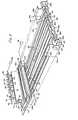
- the illustrated electrostatic copying apparatus has a nearly rectangular pararellpipedal main housing 2.
- a stationary transparent plate 4 On the upper surface of the main housing 2 is disposed a stationary transparent plate 4 on which to place a document (not shown) to be copied.
- An openable document holding member 6 for covering the transparent plate 4 and the document thereon is also provided on the upper surface of the main housing 2.
- a rotating drum 8 is rotatably mounted at the nearly central portion of the inside of the main housing 2, and an electrostatic photosensitive member 10 is disposed on the peripheral surface of the rotating drum 8.
- the rotating drum 8 is adapted to be rotated in the direction shown by an arrow 12 whereby the photosensitive member 10 is moved through an endless circular moving passage defined by the peripheral surface of the rotating drum 8.
- an endless belt having a photosensitive member disposed on its surface may be used instead of the rotating drum.
- Around the rotating drum 8 are defined a latent electrostatic image-forming zone 14, a developing zone 16, a transfer zone 18 and a cleaning zone 20 in this order as viewed in the direction of arrow 12.
- the latent electrostatic image-forming zone 14 includes a charging zone 22 and an exposing zone 24, and a charging corona discharge device 26 is disposed in the charging zone 22.
- a developing device 28 is located in the eveloping zone 16, and a transfer corona discharge device 30 is disposed in the transfer zone 18.
- the cleaning zone 20 includes a charge eliminating zone 32 and a residual toner removing zone 34.
- a charge eliminating lamp 36 is provided in the charge eliminating zone 32, and a residual toner removing device 38 is disposed in the residual toner removing zone 34.
- the optical unit 40 includes a movable document illuminating lamp 42, a movable first reflecting mirror 44, a movable second reflecting mirror 46, a stationary in-mirror lens 48 and a stationary third reflecting mirror 50.
- the document illuminating lamp 42, the first reflecting mirror 44 and the second reflecting mirror 46 are adapted for reciprocation between the position shown by a solid line and the position shown by a two-dot chain line.
- the document illuminating lamp 42 and the first reflecting mirror 44 are moved at a predetermined speed to the right from the position shown by a solid line, and the second reflecting mirror 46 is moved at a speed half of the aforesaia predetermined speed to the right from the position shown by a solid line.
- a document placed on the transparent plate 4 is illuminated and scanned by the lamp 42, and the reflecting light from the document is projected onto the photosensitive member 10 in the exposing zone 24 via the first reflecting mirror 44, the second reflecting mirror 46, the in-mirror lens 48 and the third reflecting mirror 50.
- each of the push-up means 54a and 54b is selectively held at its operating position shown by a solid line and at its non-operating position shown by a two-dot chain line by a suitable means (not shown).
- On the paper cassette receiving section 52a is detachably mounted an ordinary copying paper cassette 58 which in cooperation with it constitutes a copying paper feeding means.
- the paper cassette 58 has a box-like case 60, a carrier plate 62 whose rear end portion is pivotably connected to the bottom wall of the case 60 and a layer of copying paper sheets 64 whose front half portion is placed on the carrier plate 62.
- the push-up means 54a at its operating position projects into the case 60 through an opening formed in the bottom wall of the case 60 and elastically biases the carrier plate 62 and the paper layer 64 upwardly to push the uppermost copying paper of the paper layer 64 against the delivery roller 56a.
- an assembly shwon generally at 66 (which will be described in detail hereinbelow) is detachably mounted on the lower paper cassette receiving section 52b instead of an ordinary paper cassette.
- a copying paper receiving means 68 which may be a receiving tray.
- a copying paper conveying means shown generally at 70 is also provided within the main housing 2.
- the paper conveying means 70 includes conveying roller units 72, 74, 76, 78 and 80, and a discharge roller unit 82.
- a pair of guide plates 84 are disposed between the paper cassette receiving section 52a and the conveying roller unit 72, and a pair of guide plates 86 are disposed between the conveying roller unit 72 and the conveying roller unit 74.
- a pair of guide plates 88 are provided between the conveying roller unit 74 and the conveying roller unit 76.
- a pair of guide plates 90 are disposed between the paper cassette receiving section 52b and the conveying roller unit 74. Downstream of the conveying roller unit 78 are located a pair of guide plates 92.
- a fixing means 94 which may be of the heating and pressing type is disposed between the guide plate pair 92 and the conveying roller unit 80.
- the above structure of the illustrated elelctro- static copying apparatus except the assembly 66 may be the same as in known electrostatic copying apparatuses for forming an image only on one surface of a copying paper. A detailed description of this known structure is therefore omitted in the present specification.
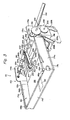
- a copying paper swerving means 96 is disposed between the conveying roller unit 80 and the discharge roller unit 82.
- the illustrated paper swerving means 96 is comprised of a shaft 98 mounted rotatably at a predetermined position within the main housing 2 and a plurality of swerving members 100 fixed to the shaft 98 and spaced from each other in the axial direction (the direction perpendicular to the sheet surface in Figure 1).
- Each of the swerving members 100 is nearly triangular and has nearly flat guide surfaces 102 and 104 and a swerving surface 106 curved in a concave shape.
- a suitable positioning means 108 such as an electromagnetic solenoid is connected to the shaft 98.
- the paper swerving means 96 When the positioning means 108 is in the deenergized state, the paper swerving means 96 is held at its non-operating position shown by a solid line in Figure 1 and a two-dot chain line in Figure 2. When it is energized, it is rotated to its operating position shown by a two-dot chain line in Figure 1 and a solid line in Figure 2. It will be readily understood from Figure 1 that when the paper swerving means 96 is held at the non-operating position, a copying paper from the conveying roller unit 80 is guided by the guiding surface 102 and conducted to the discharge roller unit 82. When the swerving means 96 is held at the operating position, the paper from the conveying roller unit 80 abuts against the swerving surface 106 and is swerved downwardly by the action of the swerving surface 106.
- Guide members 110, 112 and 114 are fixed in position below the paper swerving means 96. These guide members 110, 112 and 114 define a guide passage 118 extending from the swerving surface 106 of the paper swerving means 96 held at its operating position to an opening 116 formed in the bottom wall of the main housing 2 and a return guide passage 120 extending from the downstream portion, i.e. the lower end portion, of the guide passage 118 to a position immediately upstream of the discharge roller unit 82.
- a subsidiary housing 122 having a relatively low height is separably combined with the underside of the main housing 2.
- upstanding side plates 124a and 124b spaced from each other in the widthwise direction are disposed, and horizontal supporting walls 126a and 126b projecting substantially horizontally and outwardly in the widthwise direction are formed respectively at the upper ends of the side plates 124a and 124b.
- the main housing 2 is placed on the horizontal supporting walls 126a and 126b, and is releasably connected to the horizontal supporting walls 126a and 126b by a suitable connecting means (not shown) such as bolts and nuts.
- a conveying direction controlling roller unit 128 located adjacent the opening 116 ( Figure 1) formed in the bottom wall of the main housing 2.
- the conveying direction controlling roller unit 128 is comprised of a driven roller 128a and a follower roller 128b.
- a driving source 130 which may be a reversible electric motor.
- the shaft 132a of the driven roller 128a is drivingly connected to the driving source 130.
- the shaft of a driven roller of the discharge roller unit 82 mounted within the main housing 2 is also drivingly connected to the driving source 130 by a suitable power transmission means (not shown).
- the conveying direction controlling roller unit 128 and the discharge roller unit 82 are adapted to be driven by the driving source 130 (movable elements disposed within the main housing 2, such as the rotating drum 8, the document illuminating lamp 42 and the first and second reflecting mirrors 44 and 46 of the optical unit 40, the delivery rollers 56a and 56b, the conveying roller units 72, 74, 76, 78 and 80 and the fixing means 94 are drivingly connected to a main driving source (not shown) which may be an electric motor disposed within the main housing 2, through a suitable clutch means or the like, and driven by this main driving source).
- a movable copying paper guiding means 132 is provided below the conveying direction controlling roller unit 128.
- the movable copying paper guiding means 132 is formed of a box-like member having an open upper and and an open lower end and rotatably mounted between the side plates 124a and 124b by rotatably fitting pins 134 fixed in both sides of the box-like membe- in the side plates 124a and 124b.
- a suitable positi - Lng means 136 such as an electromagnetic solenoid is connected to the copying paper guiding means 132.
- the positioning means 136 is in the deenergized state, the paper guiding means 132 is held at a first position shown by a solid line in Figures 1 and 2.
- the paper guiding means 132 When the positioning means 136 is energized, the paper guiding means 132 is held at a second position shown by a two-dot chain line in Figures 1 and 2.
- Guide plates 138 and 140 are fixed in position between the side plates 124a and 124b in relation to the lower end of the paper guiding means 132 at its second position.
- the guide plate 138 extends from its inside end opposite to the lower end of the paper guiding means 132 in its second position to the left in Figure 1, and the guide plate 140 extends above and along the guide plate 138.
- a copying paper returning means shown generally at 142 is further provided between the side plates 124a and 124b in the subsidiary housing 122.
- shafts 144 and 146 spaced from each other in the lateral direction are rotatably mounted across the side plates 124a and 124b.
- a plurality of axially spaced pulleys 148 are fixed to each of the shafts 144 and 146, and endless belts 150 are wrapped about the pulleys 148.
- a driving source 152 which may be an electric motor is disposed rearwardly of the side plate 124b, and the shaft 146 is drivingly connected to the driving source 152.
- the endless belts 150 are driven in the direction shown by an arrow 154.
- One end portion, i.e. the left end portion in Figure 1, of the upper running section of each endless belt 150 is positioned immediately below the lower end of the paper guiding means 132 in its first position.
- a copying paper discharged from the lower end of the paper guiding means 132 is conducted to the upper running sections of the endless belts 150 and then conveyed in the direction shown by arrow 154 by the action of the endless belts 150 driven in the direction of arrow 154.
- a return roller unit 156 is further provided in the right end portion in Figure 1 of the subsidiary housing 122.
- a supporting member 158a or 158b is mounted on one end portion of the side plate 124a or 124b, respectively.
- each of the supporting members 158a and 158b is mounted on the side plate 124a or 124b so that its rotating angular position formed with the rotating central axis of the shaft 146 as a center can be freely adjusted.
- Shafts 160a and 160b are rotatably mounted across the supporting members 158a and 158b, and a plurality of rollers 162a or 162b are fixed to the shaft 160a or 160b.
- One end of the shaft 146 projects forwardly beyond the side plate 124a, and a gear 164 is fixed to this one end.
- One end of the shaft 160a projects forwardly beyond the supporting member 158a, and a gear 166 is fixed to this one end.
- a gear 168 in mesh with both the gears 164 and 166 is rotatably mounted on the supporting member 158a. Accordingly, when the shaft 146 is driven in the direction of arrow 154 by the driving source 152, the return roller unit 156 is rotated in the direction of arrow 154 via the gears 164, 168 and 166.
- the return roller unit 156 nips the copying paper conveyed by the endless belts 150 and sends it between guide plates provided in the assembly 66 ( Figure 1) to be described below in detail.
- the position of the return roller unit 156 with respect to the introduction end of the pair of guide plates in the assembly 66 can be adjusted as desired by adjusting the rotating angular positions of the supporting members 158a and 158b.
- the assembly 66 which is mounted detachably instead of an ordinary copying paper cassette on the lower copying paper cassette receiving section 52b formed at the right end portion of the main housing 2.
- the assembly 66 includes a supporting frame 172 having side walls 170a and 170b spaced from each other in the widthwise direction (the direction perpendicular to the sheet surface in Figure 1).
- the side walls 170a and 170b respectively have nearly rectangular front portions 174a and 174b extending laterally (in the left-right direction in Figure 1) and nearly rectangular rear portions 176a and 176b extending vertically.
- a bottom wall 176 is fixed across the lower end edges of the front portions 174a and 174b of the side walls 170a and 170b.
- a front wall 178 is fixed across the front end edges of the front portions 174a and 174b of the side walls 170a and 170b.
- a box-like copying paper receiving receptacle 180 having an open upper surface and an open rear surface is defined by the front portions 174a and 174b of the side walls 170a and 170b and the bottom wall 176 and the front wall 178.
- the bottom wall 176 has an opening 182 through which the push-up means 54b disposed in the lower paper cassette receiving section 52b can extend.
- Plate-like members 184a and 184b are disposed inwardly of the front portions 174a and 174b of the side walls 170a and 170b respectively, and separating claws 186a and 186b are formed as an integral unit on the front end and upper end of the plate-like members 184a and 184b, respectively.
- the rear end portions of the plate-like members 184a and 184b are pivotably connected to the front portions 174a and 174b of the side walls 170a and 170b respectively, and the plate-like members 184a and 184b can freely pivot over some angular range (the pivotal movement of the plate-like members 184a and 184b is restricted by the contacting of suitable contacting portions (not shown) defined in the plate-like members 184a and 184b with the upper surface of the bottom wall 176). Hence, the separating claws 186a and 186b can move up and down freely over some range.
- a carrier plate 188 is disposed between the plate-like members 184a and 184b. The rear end of the carrier plate 188 is pivotably connected to the bottom wall 176.
- the structure of the paper receiving receptacle 180 itself including the plate-like members 184a and 184b and the carrier plate 188 is substantially the same as that of a known copying paper case in an ordinary copying paper cassette. Accordingly, a detailed description of the paper receiving receptacle 180 itself will be omitted in the present specification.
- a carrying roller unit 190 is disposed between the upper end portions of the rear portions 176a and 176b of the side walls 170a and 170b. More specifically, shafts 192a and 192b are rotatably mounted across the rear portions 176a and 176b of the side walls 170a and 170b, and a plurality of rollers 194a and 194b are fixed respectively to the shafts 192a and 192b. One end of the shaft 192a projects forwardly beyond the rear portion 176a of the side wall 170a, and a gear 196 is fixed to this one end. Furthermore, a driving source 198 which may be a reversible electric motor is fixed to the inside of the rear portion 176a of the side wall 170a.
- the output shaft 200 of the driving source 198 also projects forwardly beyond the rear portion 176a of the side wall 170a, and a gear 202 is fixed to the projecting end of the output shaft 200.
- the gear 202 is in mesh with the gear 196.
- the carrying roller unit 190 is rotated by the driving source 198.
- a shaft 204 is further mounted rotatably across the rear portions 176a and 176b of the side walls 170a and 170b, and a pivoting member 206 is pivotably mounted on the center of the shaft 204.
- the pivoting member 206 has portions 208a and 208b inclined forwardly and extending downwardly from the shaft 204 while being spaced from each other substantially parallel to each other.
- a shaft 210 is rotatably mounted on the free end portions of the portions 208a and 208b. To both ends of the shaft 210 is mounted a roller 214 via a one-way clutch 212. The one-way clutch 212 transmits the rotation of the shaft 210 to the roller 214 only when the shaft 210 is rotated in the direction shown by an arrow 216.
- a pulley 218 is fixed to the center of the shaft 210, and a pulley 220 is also fixed to that part of the shaft 204 which is between the portions 208a and 208b of the pivoting member 206.
- An endless belt 222 is wrapped about the pulleys 218 and 220.
- One end of the shaft 204 projects forwardly beyond the rear portion 176a of the side wall 170a, and a gear 224 is fixed to this one end.
- the gear 224 is in mesh with the gear 196. Accordingly, the shafts 204 and 210 are also rotated by the driving source 198.
- the roller 214 is rotated in the direction shown by arrow 216.
- the pivoting member 206 and the rollers 214 mounted thereon, which constitute an auxiliary advancing means, are biased downwardly by their own weight, and consequently, the rollers are brought into contact with the upper surface of the bottom wall 176 of the paper receiving receptacle 180.
- a pair of guide plates 226a and 226b inclined slightly forwardly and extending downwardly from their upper ends approximating the nipping portion of the carrying roller unit 190 are fixed across the rear end portions 176a and 176b of the side walls 170a and 170b.
- a rear wall 228 is fixed across the rear end edges of the rear portions 176a and 176b of the side walls 170a and 170b.
- a rearwardly extending projecting portion 230 is formed as a unit at the upper end of the rear wall 228 which is located slightly below the nipping position of the carrying roller unit 190.
- An additional copying receiving means 232 which may be a receiving tray is detachably mounted on the projecting portion 230.
- the assembly 66 When as shown in Figure 1 the assembly 66 is mounted on the lower paper cassette receiving section 52b formed in the main housing 2, the lower ends of the guide plates 226a and 226b stand opposite to the return roller unit 156 of the paper returning means 142 provided in the subsidiary housing 122. Consequently, the copying paper discharged from the return roller unit 156 is introduced between the guide plates 226a and 226b and guided by the carrying roller unit 190.
- the copying paper is conveyed rearwardly in a direction away from the paper receiving receptacle 180 while it is nipped by the carrying roller unit 190 rotated normally (i.e., in the direction of an arrow 234).
- the carry roller unit 190 continues to rotated normally, the copying paper is discharged into the additional paper receiving means 232.
- the carry roller unit 190 is rotated reversely, namely in the direction of an arrow 236, immediately after the trailing end of the copying paper has left the upper ends of the guide plates 226a and 226b and while the trailing end portion of the copying paper is still nipped by the carrying roller unit 190.
- the copying paper is conveyed with its leading and trailing ends reversed, and carried into the paper receiving receptacle 180 after passing above the guide plates 226a and 226b.
- the illustrated electrostatic copying paper further has a detecting means to be described.
- a paper stacking detecting means 238 is provided between the fixing means 94 and the conveying roller unit 80.
- the detector 238 which can be constructed of a light receiving element and a light emitting element and may be of a known type detects the state of stacking of two or more copying paper sheets (at which time the light transmittance of the copying paper sheets is below a predetermined threshold value) and produces an output signal.
- a copying paper detector 240 is provided immediately upstream of the conveying direction controlling roller unit 128, and as also shown in Figure 1, a copying paper detector 242 is also provided immediately upstream of the carrying roller unit 190.
- These detectors 240 and 242 each of which may be constructed of a light receiving element and a light emitting element and be of a known type detect the leading edge of the copying paper and produce an output signal.
- the output signals produced by the detectors 238, 240 and 242 are fed into a control means 244 ( Figure 4) for controlling the operation of the electrostatic copying apparatus.
- the control means may be a microprocessor.
- the rotating drum 8 is rotated in the direction of arrow 12.
- the surface of the photosensitive member 10 on the rotating drum is charged to a specific polarity by the charging corona discharge device 26.
- the image of a document placed on the transparent plate 4 is scanned by the optical unit 40 and projected onto the photosensitive member 10.
- a latent electrostatic image corresponding to the image of the document is formed on the photosensitive member 10.
- a toner is applied to the latent electrostatic image on the photosensitive member 10 by the developing device 28 to develop the latent electrostatic image to a toner image.
- a copying paper conveyed through the transfer zone 18 (the conveying of the copying paper will be described hereinafter) is brought into contact with the surface of the photosensitive member 10, and by the action of the transfer corona discharge device 30, the toner image on the photosensitive member 10 is transferred to the upper surface of the copying paper.
- the copying paper having the toner image transferred thereto is peeled off from the surface of the photosensitive member 10 and conveyed to the fixing means 94 where the toner image is fixed to the upper surface of the copying paper.
- the charge eliminating zone 32 light from the charge eliminating lamp is irradiated onto the photosensitive member 10, and a residual charge on the photosensitive member 10 is erased.
- the residual toner removing zone 34 the residual toner is removed from the surface of the photosensitive member 10 by the residual toner removing device 38.
- the paper swerving means 96 is held at its non-operating position shown by a solid line in Figure 1.
- the copying paper delivered from the paper cassetter 58 mounted on the upper paper cassette receiving section 52a is conveyed through the transfer zone 18 and the fixing means 94 (therefore, an image is produced on the upper surface of the paper). Then, it is conveyed over the guide surface 102 of the paper swerving means 96 and discharged into the paper receiving means 68.
- the assembly 66 mounted on the lower paper cassette receiving section 52b mount an ordinary copying paper cassette also on the lower paper cassette receiving section 52b, and deliver a copying paper selectively from either one of the cassette 58 mounted on the cassette receiving section 52a and the cassette mounted on the lower cassette receiving section 52b.
- the copying paper sheets in the cassette 58 may be different in size from those placed in the cassette mounted on the cassette receiving section 52b.
- a copying paper return switch 246 ( Figure 4) provided in an operating panel (not shown) disposed on the upper or front surface of the main housing 2 is manually operated.
- the paper swerving means 96 is held at the operating position shown by a two-dot chain line in Figure 1 and a solid line in Figure 2.
- the push-up means 54b provided in the lower paper cassette receiving section 52b is held at the non-operating position shown in Figure 1 by a two-dot chain line.
- the movable copying paper guiding means 132 is held at the first position shown by a solid line in Figures 1 and 2.
- the copying paper which has been swerved downwardly is moved along the guide passage 118 and sent to the conveying direction controlling roller unit 128 which is normally rotated (i.e., in the direction of arrow 248) by the driving source 130 ( Figure 2).
- the conveying direction controlling roller unit 128 sends the copying paper to the endless belts 150 of the paper returning means 142 through the movable paper guiding means 132. It will be easily understood by reference to Figure 1 that when the paper has been fed to the endless belts 150 as above, the copying paper is turned upside down and placed on the endless belts 150 with its image-bearing surface 113 directed downwardly.
- the endless belts 150 are driven in the direction of arrow 154 by the driving source 152 ( Figure 2), and send the copying paper in the direction of arrow 154 to the return roller unit 156.
- the return roller unit 156 rotating in the direction of arrow 154 by the driving source 152 ( Figure 2) introduces the copying paper between the guide plates 226a and 226b provided in the assembly 66, and sends it to the carrying roller unit 190 between the guide plates 226a and 226b.
- the carrying roller unit 190 is rotated normally (i.e. in the direction of arrow 234) by the driving source 198 ( Figure 3).
- the copying paper nipped by the carrying roller unit 190 is conveyed rearwardly, i.e.
- the detector 242 disposed immediately upstream of the carrying roller unit 190 detects the leading edge of the copying paper and produces an output signal.
- the control means 244 ( Figure 4) reverses the rotation of the driving source 198.
- the trailing end of the copying paper conveyed rearwardly by the carrying roller unit 190 has already gone past the guide plates 226a and 226b, but its trailing end portion is still nipped by the carrying roller unit 190.
- the delay time can be prescribed by a timer built in the control means 244.
- Returning of the driving source 198 to a normally rotating condition may be effected at a time after the lapse of a relatively long predetermined delay time from the production of the output signal by the detector 242.
- This delay time can also be prescribed by a timer built in the control means 244 ( Figure 4).
- two or more paper sheets may be delivered in the stacked state from the paper cassette 58 mounted on the upper cassette receiving section 52a although this rarely happens.
- the detector 238 disposed downstream of the fixing means 94 detects the stacked copying paper sheets and produces an output signal.
- the driving source 198 is not reversed even after the lapse of the aforesaid predetermined delayed time from the time when the detector 242 located immediately upstream of the carrying roller unit 190 detects the leading edge of the copying paper and produces an output signal.
- the carrying roller unit 190 continues to be normally rotated in the direction of arrow 234.
- the stacked copying paper sheets are therefore not carried into the paper receiving receptacle 180, but discharged into the additional paper receiving means 232.
- the operator manually operates a re-feeding switch 250 ( Figure 4) provided in the operating panel (not shown).
- a re-feeding switch 250 Figure 4
- the paper swerving means 96 is returned to the non-operating position shown by a solid line in Figure 1 and a two-dot chain line in Figure 2.
- the push-up means 54b provided in the lower paper cassette receiving section 52b is returned to the operating position shown by a solid line in Figure 1, and therefore, the carrier plate 188 and the copying paper thereon in the paper receiving receptacle 180 are elastically biased upwardly to push the paper against the delivery roller 56b.
- the copying cycle is resumed, and with the rotation of the delivery roller 56b, the copying paper is delivered from the paper receiving receptacle 180.
- the delivered copying paper is conveyed through the transfer zone 18 and the fixing means 94, and an image is formed on the upper surface of the copying paper, anmely on that surface which is opposite to that surface on which the image was first formed.
- the copying paper is conveyed over the guide surface 102 of the paper swerving means 96 at its non-operating position shown by a solid line in Figure 1 and a two-dot chain line in Figure 2, and discharged into the paper receiving means 68. Consequently, a copy bearing an image on both surfaces is obtained.
- the last page to be copied may sometimes be an odd-numbered page.
- an image must be formed on both surfaces of a copying paper (namely the image of an odd-numbered page is formed on one surface of the copying paper and the image of an even-numbered page is formed on the other surface) excepting the last page, and the image of the last page needs to be formed only on one surface of a copying paper.
- the copying paper is discharged into the paper receiving means 68 with both its front and back surfaces and its leading and trailing ends reversed.
- so-called sorter when so- called sorter is used as the paper receiving means 68, it is desired to discharge the copying paper having the image of the final page formed on its one surface into the paper receiving means 68 also with both its front and back surfaces and its leading and trailing ends reversed and thus to set page numbers in the right order. Also, in a usual case of producing an image on one surface of a copying paper, it is sometimes desired to discharge the copying paper bearing an image only on one surface into the paper receiving means 68 with its front and back surfaces and its leading an trailing ends reversed.
- a reverse discharge switch 252 ( Figure 4) provided in the operating panel (not shown) is first manually operated.
- the paper swerving means 96 is held at its operating position shown by a two-dot chain line in Figure 1 and a solid line in Figure 2, and the movable paper guiding means 132 is held at its second position shown by a two-dot chain line in Figures 1 and 2.
- the copying paper conveyed by the conveying direction controlling roller unit 128 moves through the movable paper guiding means 132 held at the non-operating position shown by a two-dot chain line in Figures 1 and 2. As a result, it is not directed to the paper returning means 142 but guided between the guide plates 138 and 140 in a direction away from the paper returning means 142.
- the detector 240 disposed immediately upstream of the conveying direction controlling roller unit 128 detects the leading edge of the copying paper and produces an output signal.
- the control means 244 ( Figure 4) reverses the rotation of the driving source 130 ( Figure 3) after the lapse of a predetermined delay time from the production of the output signal by the detector 240.
- the trailing end portion of the copying paper conveyed by the conveying direction controlling roller unit 128 is still nipped by the conveying direction controlling roller unit 128.
- the delay time can be prescribed by a timer built in the control means 244 ( Figure 4).
- the driving source 130 ( Figure 2) is reversed, the conveying direction controlling roller unit 128 is rotated reversely, namely in the direction of arrow 254.
- the discharge roller unit 82 is also drivingly connected to the driving source 130 ( Figure 2).
- a suitable reverse rotation transmitting means known per se (not shown) is disposed between the driving source 130 and the discharge roller unit 82, and as soon as the rotation of the driving source 130 is reversed, this reverse rotation transmitting means is actuated.
- the rotating direction of the discharge roller unit 82 is not reversed.
- the conveying direction controlling roller unit 128 is rotated in the direction of arrow 254
- the copying paper is conveyed upwardly with its leading and trailing edge reversed, and sent to the discharge roller unit 82 through the return guide passage 120.
- the discharge roller unit 82 the copying paper is discharged into the paper receiving means 68 with its front and back surfaces reversed.
- the driving source 130 ( Figure 2) is again returned to its normally rotating condition. Returning of the driving source 130 to its normally rotating condition may be effected at a time after the lapse of a relatively long delay time from the production of the output signal by the detector 240. This delay time can also be prescribed by a timer built in the control means 244 ( Figure 4).
- the rotating speed of the driving source 130 ( Figure 2) during reverse rotation is made higher than that during normal rotation.
- the conveying direction controlling roller unit 128 is rotated reversely, namely rotated in the direction of arrow 254 and the copying paper is discharged with its front and back surfaces and its leading and trailing ends reversed
- the rotating speeds of the conveying direction controlling roller unit 128 and the discharge roller unit 82 are made high. This reduces the delay in the completion of paper discharge when the paper is discharged with its front and back surfaces and its leading and trailing ends reversed.
- the above problem may also be avoided by delaying the conveying of the copying paper delivered from the paper cassetter 58 (or from the paper receiving receptacle 180) for the next cycle of copying by at least a certain period of time.
- This delaying may be performed, for example, by rotating the delivery roller 56a (or the delivery roller 56b) after the lapse of a longer predetermined period of time from the time when the preceding copying paper has been delivered from the paper cassette 58 mounted on the upper cassette receiving section 52a, and thus delivering the copying paper from the cassette 58 (or from the paper receiving receptacle 180) after the lapse the of this period.
- the above predetermined time can be prescribed by a timer built in the control means 244 ( Figure 4).
- a copying paper which has been delivered from the cassette 58 mounted on the upper cassette receiving section 52a and transferred through the transfer zone 18 and fixing means 94 and thus has an image formed on its upper surface is swerved downwardly by the swerving surface 106 of the paper swerving means 96 on the downstream side of the conveying roller unit 80.
- the copying paper is sent to the carrying roller unit 190 in the assembly 66 through the conveying direction controlling roller unit 128, the movable paper guiding means 132 and the paper returning means 142 as stated hereinabove.
- the carrying roller unit 190 is rotated normally in the direction of arrow 234 by the driving source 198 ( Figure 3).
- the drivin q source 198 is not rotated reversely even after the lapse of the aforesaid predetermined delay time after the production of the output signal by the detector 242, and therefore, the carrying roller unit 190 continues to rotate normally in the direction of arrow 234.
- the copying paper in the interrupting copying cycle is discharged into the additional paper receiving means 232 unlike other copying papers to be discharged into the paper receiving means 68.
- Figures 5 to 7 depict a second embodiment of the assembly which can be mounted on the lower paper cassette receiving section 52b in the main housing 2 instead of the assembly 66 described above.
- the assembly is shown generally at 300, and indludes a supporting frame 304 having side walls 302a and 302b spaced from each other in the widthwise direction (the up and down direction in Figure 6) and extending laterally (in the left-right direction in Figure 6).
- a bottom wall 306 is fixed across the front portions of the side walls 302a and 302b, and a front wall 308 is fixed across the front edges of the side walls 302a and 302b.
- a box-like paper receiving receptacle 310 having an open upper surface and an open rear surface is defined by the front portion of the side walls 302a and 302b, the bottom wall 306 and the front wall 308.
- an opening 312 ( Figure 6) through which the push-up means 54b ( Figure 1) disposed in the lower paper cassette receiving section 52b in the main housing 2 can extend.
- side edge restricting plates 314a and 314b are fixed to the bottom wall 306 slightly inwardly of the front portions of the side walls 302a and 302b.
- Outwardly of the side edge restricting plates 314a and 314b are disposed plate-like members 316a and 316b.
- Separating claws 318a and 318b projecting inwardly in the widthwise direction beyond the side edge restricting plates 314a and 314b are formed as an integral unit on the front end and upper end of the plate-like members 316a and 316b respectively.
- the rear end portion of the plate-like members 316a and 316b are connected pivotably to the side edge restricting plates 314a and 314b respectively by pins 320a and 320b, and the plate-like members 316a and 316b can pivot freely over some angular range (the pivoting of the plate-like members 316a and 316b is restricted by the contacting of suitable contacting portions (not shown) defined in the plate-like members 316a and 316b with suitable portions to be contacted (not shown) defined in the side edge restricting plates 314a and 314b).
- a carrier plate 322 is disposed between the side edge restricting plates 314a and 314b.
- a plurality of bent portions 324 extending downwardly and then rearwardly and spaced from each other in the widthwise direction are formed in the rear end of the carrier plate 322.
- a plurality of openings 326 spaced from each other in the widthwise direction are formed in the bottom wall 306.
- the above-described structure of the paper receiving receptacle 310 in the assembly 300 is substantially the same as a known copying paper case in an ordinary paper cassette.
- the following improvement, however, has been made in the paper receiving receptacle 310 in the assembly 300 so that it can be used for two types of paper sheets having different widthwise sizes.
- an additional side edge restricting plate 328 is disposed inwardly of the side edge restricting member 314b in the widthwise direction by a predetermined distance.
- An additional separating claw 330 is formed as a unit at the front end and upper end of the additional side edge restricting plate 328.
- the front portion of the additional side edge restricting plate 328 extends substantially parallel to the side edge restricting plate 314b, but its rear portion extends reawardly and inclined slightly outwardly in the widthwise direction.
- a linking member 332 extending from there outwardly in the widthwise direction.
- the linking member 332 extends through openings (not shown) formed in the side edge restricting plate 314b and the plate-like member 316b, and a lever 334 is fixed to the outside end of the linking member 332.
- the rear end portion of the lever 334 is pivotably connected to the side edge restricting plate 314b by the pin 320b.
- the additional side edge restricting plate 328 can freely pivot over some angular range (the pivoting of the additional side edge restricting plate 328 is restricted by the contacting of a suitable contacting portion (not shown) defined in the additional side edge restricting plate 328 with a suitable portion to be contacted (not shown) defined in the side edge restricting plate 314b and/or the upper surface of the bottom wall 306).
- the additional separating claw 330 can move up and down over some range.
- the lowermost position of the additional separating claw 330 is the position shown in Figure 7 and is set slightly lower than the lowest position of the claws 318a and 318b, i.e. the position shown in Figure 7.
- a cut 336 corresponding to the additional side edge restricting plate 328 and the additional separating claw 330 is formed in the carrier plate 322 and an elevating means 338 is provided for selectively elevating the carrier plate 322 from a lowered position shown by a solid line in Figure 7 to an elevated position shown by a two-dot chain line in Figure 7.
- the elevating means 338 includesan electromagnetic solenoid 340 fixed to the lower surface of the bottom wall 306, a linking lever 342 and a swivel lever 344.
- the swivel lever 344 is mounted pivotably about a pin 346 as a center, and the upper end of the swivel lever 344 projects upwardly through an opening 348 (see Figure 6 also) formed in the bottom wall 306.
- One end of the linking lever 342 is pivotably linked to the iron core of the electromagnetic solenoid and the other end is pivotably linked to the lower end of the swivel lever 344.
- the electromagnetic solenoid 340 is energized and the carrier plate 322 is elevated to the elevated position shown by a two-dot chain line in Figure 7.
- the additional side edge restricting plate 328 and the additional separating claw 330 are located below (or on nearly the same level as) the upper surface of the carrier plate 322.
- the copying paper of a relatively large width which is advanced over the carrier plate 322 in the manner described below and carried into the paper receiving receptacle 310 is not interfered with by the additional side edge restricting plate 328 and the additional separating claw 330.
- the electromagnetic solenoid 340 is deenergized, and the carrier plate 322 is held at the lowered position shown by a solid line in Figure 7.
- the additional side edge restricting plate 328 and the additional separating claw 330 project upwardly beyond the upper surface of the carrier plate 322 through the recess 336 formed in the carrier plate 322.
- the copying paper of a relatively small width is advanced over the carrier plate 322, one side edge of the copying paper is guided by the additional side edge restricting plate 328 and carried as desired into the paper receiving receptacle 310.
- the push-up means 54b disposed in the lower paper cassette receiving section 52b of the main housing 2 is held at the operating position shown by a solid line in Figure 1, and therefore, the carrier plate 322, the copying paper on it, and the separating claws 318a and 318b (or the separating claw 318a and the additional separating claw 330) are elastically biased upwardly to a predetermined position to push the copying paper against the delivery roller 56b (see Figure 1 also).
- the carrier plate 322 is elevated to the elevated position when the copying paper having a relatively large width is carried into it. If desired, however, it is possible instead to lower the additional side edge restricting plate 328 and the additional separating claw 330 below the position shown in Figure 7 and thus bring them to a position below (or to nearly the same level as) the upper surface of the carrier plate 322.
- the above improvement in the paper receiving receptacle 310 in the assembly 300 may also be applied to the paper receiving receptacle 180 in the assembly 66 illustrated in Figure 3.
- a reverse carrying means shown generally at 350 is provide in the assembly 300 rearwardly of the paper receiving receptacle 310.
- the reverse carrying means 350 includes a moving plate 352 to be selectively held at a receiving position shown by a two-dot chain line in Figures 5 and 7 and a solid line in Figure 6 and transfer position shown by a solid line in Figures 5 and 7 and a two-dot chain line in Figure 6.
- Upstanding side walls 354a and 354b are formed on both side edges of the moving plate 352.
- Linking levers 360a and 362a and 360b and 362b are pivotably linked at their one end to the short shafts 356a and 358a and 356b and 358b, respectively, and pivotably linked at their other end to the upstanding side walls 354a and 354b of the moving plate.
- the moving plate 352 is caused to pivot between the receiving position and the transfer position about the short shafts 356a and 358a and 356a and 358b as a center of pivotiang (means for pivoting the moving plate 352 will be described hereinafter).
- a transfer means 364 formed of a plate-like member extending in the widthwise direction (the up and down direction in Figure 6). The transfer means 364 can move freely in the front-rear direction over the moving plate 352 (means for moving the transfer means 364 will be described hereinafter).
- a conveying roller unit 366 is provided between the side walls 302a and 302b in relation to the front edge portion of the moving plate 352 held at tis receiving position.
- a shaft 368 is rotatably mounted across the side walls 302a and 302b, and a plurality of rollers 370 spaced from each other in the widthwise direction are fixed to the shaft 368.
- a plurality of cuts 372 spaced from each other in the widthwise direction are formed in the front edge portion of the moving plate 352, and when the moving plate is held at the receiving position, the rollers 370 are positioned partly within the cuts 372.
- a bracket 374 is pivotably mounted on both end portions of the shaft 368, and a shaft 376 is rotatably mounted across the free ends of the brackets 374, and a plurality of rollers 378 spaced from each other in the widthwise direction are fixed to the shaft 376.
- the rollers 378 are brought into contact with the rollers 370 by the weights of the shaft 376 and the rollers 378.
- a driving source 380 ( Figure 7) which may be an electric motor is fixed to the inside surface of the side wall 302b, and the shaft 368 is drivingly connected to the driving source 380.
- the conveying roller unit 366 is rotated in the direction shown by an arrow 382 ( Figure 7) by the driving source 380.
- Guide plates 384a and 384b whose upper ends are close to the conveying roller unit 366 are fixed across the side walls 302a and 302b.
- a horizontal supporting wall 388 is fixed across the lower ends of the suspending walls 386a and 386b.
- a driving source 390 which may be a reversible electric motor and a driving connection controlling means 392 constructed of an electromagnetic solenoid.
- three upstanding plates 394, 396 and 398 spaced in the widthwise direction between the driving source 390 and the driving connection controlling means 392 are fixed to the supporting wall 388.
- the output shaft 400 of the driving source 390 extends through the upstanding plate 394, and a gear 402 is fixed to the forward end of the output shaft 400.
- Shafts 404, 406 and 408 are rotatably mounted across the upstanding plates 394 and 396.
- a gear 410 is fixed to the shaft 404, a gear 412 is fixed to the shaft 406, and a gear 414 is fixed to the shaft 408.
- the gear 410 is in mesh with the gear 402, and the gear 414 is in mesh with the gear 412.
- Shafts 418 and 420 are rotatably mounted across the upstanding plates 396 and 398.
- a gear 422 is fixed to the shaft 418, and gears 424 and 426 are fixed to the shaft 420.
- the gear 426 is in mesh with the gear 422.
- a protrusion 428 is formed in the gear 422.
- a shaft 430 is rotatably and axially movably mounted on the upstanding plates 394, 396 and 398 and extends through the upstanding plates.
- a gear 432 located between the upstanding plates 394 and 396 and a gear 434 located between the upstanding plates 396 and 398.
- a nearly L-shaped member 436 is fixed to the iron core of the electromagnetic solenoid constituting the driving connection controlling means 392, and one end of the shaft 430 is linked to the member 436 so that it is freely rotatable but cannot move relatively in the axial direction.
- the gears 432 and 434 fixed to the shaft 430 are located at the position shown by a solid line, the gear 432 is in mesh with the gear 410, and the gear 434 is in mesh with the gear 426. Accordingly, the driving source 390 is drivingly connected to the gear 422 via the gears 402, 410, 432, 426 and 424.
- the gears 432 and 434 fixed to the shaft 430 are moved to the positions shown by two-dot chain lines. Consequently, the gear 432 is brought into mesh not only with the gear 410 but also with the gear 412.
- the driving source 390 is drivingly connected to the shaft 408 via the gears 402, 410, 432, 412 and 414.
- the gear 434 is detached from the gear 426 and the gear 422 is cut off from the driving source 390.
- a supporting bracket 438 is fixed to the under surface of the rear end portion of the moving plate 352, and a shaft 440 is rotatably mounted on the bracket 438.
- the free end of the protrusion 428 formed in the gear 422 is pivotably connected to the shaft 440.
- Pulleys 446a and 446b are fixed to both ends of the shaft 440 mounted rotatably on the supporting bracket 438.
- An endless belt 448 is wrapped about the shaft 440 and the shaft 408.
- a supporting bracket similar to the supporting bracket 438 is fixed to the under surface of the front end portion of the moving plate 352, and a shaft similar to the shaft 440 is rotatably mounted on such a bracket.
- pulleys similar to the pulleys 446a and 446b are fixed to both ends of such a shaft.
- An endless belt 450a is wrapped about the pulley 446a and the corresponding pulley
- an endless belt 450b is wrapped about the pulley 446b and the corresponding pulley.
- linking pieces 454a and 454b are fixed to the lower end of the central part of the rear surface of the transfer means 364, and connected to the endless belts 450a and 450b by pins 456a and 456b.
- the transfer means 364 is advanced over the moving plate 352, and when the endless belts 450a and 450b are driven in the direction shown by an arrow 460, the transfer means 364 is moved backward on the moving plate 352.
- the moving plate 352 is held at the receiving position spaced rearwardly and downwardly of the paper receiving receptacle 310 as shown by a two-dot chain line in Figure 7, and the transfer means 364 on the moving plate 352 is positioned at the rear end portion of the moving plate 352. Therefore, the copying paper discharged from the conveying roller unit 366 is moved as shown by the arrow 462 and carried onto the moving plate 352.
- the driving source 390 is energized for a predetermined period of time and rotated in a normal direction. Consequently, the moving plate 352 is held at the transfer position adjacent the paper receiving receptacle 310 as shown by a solid line in Figure 7.
- the driving connection controlling means 392 is energized and the driving source 390 is energized for a predetermined period of time and rotated in a normal direction. Consequently, the transfer means 364 on the moving plate 352 is advanced from the rear end portion to the front end portion of the moving plate 352. Thus, the copying paper on the moving plate 352 is forced forwardly by the means 364 and carried into the paper receiving receptacle 310 from the moving plate 352. Then, the driving source 390 is energized for a predetermined period of time and rotated in the reverse direction. As a result, the transfer means 364 on the moving plate 352 is moved backward from the front end portion to the rear end portion of the moving plate 352. The driving connection controlling means 392 is deenergized. Then, the driving source 390 is energized for a predetermined period of time and rotated reversely whereby the moving plate 352 is returned to the receiving position shown by a two-dot chain line in Figure 7.
- the push-up means 54b adapted to be selectively held at the operating position shown by a solid line and the non-operating position shown by a two-dot chain line is disposed in the lower paper cassette receiving section 52b located in the main housing 2 illustrated in Figure 1.
- the push-up means 54b acts on the carri or plate 188 or 322 of the paper receiving receptacle 180 or 310 in the assembly 66 or 300, and consequently, the copying paper on the carrier plate 188 or 322 is pushed against the delivery roller 56b.
- a copying paper cassette receiving section of the type having no push-up means also finds practical use as a paper cassette receiving section to be formed in the main housing (in which case means for elastically biasing the carrier plate upwardly is disposed in the paper cassette case).
- Figure 8 shows a modified example of the copying paper receiving receptacle which can be used instead of the paper receiving receptacle 180 or 310 in the assembly 66 or 300 when the paper cassette receiving section formed in the main housing 2 has no push-up means.
- a front wall 502 is fixed across the front end edges of a pair of side walls 500 (only one of which is shown in Figure 8) of the supporting frame in the assembly, and a carrier plate 504 is provided between the front end portions of the pair of side walls 500.
- a box-like paper receiving receptacle 506 having an open top surface and an open rear surface (including no bottom wall) is defined by the pair of side walls 500, the front wall 502 and the carrier plate 504.
- a plate-like member having formed as an integral unit a separating claw 508 at its front end and upper end is disposed inwardly of each of the front portions of the pair of side walls 500.
- the plate-like members may be substantially the same as the plate-like members 184a and 184b shown in Figure 3 or the plate-like members 316a and 316b shown in Figure 6.
- the separating claw 508 is shown for clear illustration. The separating claw 508 can freely move up and down between the position shown by a solid line and the position shown by a two-dot chain line.
- Linking pieces 510 extending upwardly are formed respectively at both side edges of the rear end portion of the carrier plate 504, and are pivotably connected to the pair of side walls 500 respectively by pins 512.
- the carrier plate 504 is mounted pivotably about the pin 512 as a center.
- a pivoting means shown generally at 514 is provided below the carrier plate 504.
- the pivoting means 514 includes a driving source 516 (which may be a reversible electric motor) fixed to the side wall 500 through a suitable supporting bracket (not shown) and a semicircular worm gear 520 rotatably mounted on the side wall 500 by a pin 518.
- a worm 522 in mesh with the worm gear 520 is fixed to the output shaft of the driving source 516.
- To the worm gear 520 is fixed a push-up lever 524 preferably formed of a plate spring.
- the worm gear 520 When a copying paper is carried into the paper receiving receptacle 506 described above, the worm gear 520 is held at the angular position shown by a solid line. At this time, the carrier plate 504 is positioned substantially horizontally as shown by a solid line as a result of its under surface abutting against the free end of the push-up lever 524.
- the worm gear 520 When the copying paper is delivered from the paper receiving receptacle 506, the worm gear 520 is rotated to the angular position shown by a two-dot chain line. Consequently as shown by a two-dot chain line, the carrier plate 504 is pivoted by the push-up lever 524 in a direction in which the front end portion of the plate 504 rises.
- the copying paper on the carrier plate 504 is pushed elastically against the delivery roller 56b provided in the lower cassette receiving section 52b of the main housing 2 (see Figure 1 also).
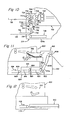
- Figure 9 shows one example of a curl correcting means which can be disposed upstream or downstream of the conveying direction controlling roller unit 128 shown in Figure 1, or instead of the conveying direction controlling roller unit 128.
- the copying paper discharged from the conveying roller unit 80 abuts against the swerving surface 106 of the paper swerving means 96, and is swerved downwardly along the swerving surface 106.
- curl in a specific direction tends to form in the copying paper.
- a curl correcting means 600 illustrated in Figure 9 corrects the curl by forcibly bending the paper in a direction opposite to the curl formed in the paper owing to the swerving of the paper.
- the curl correcting means 600 illustrated in Figure 9 includes a main roller 602, auxiliary rollers 604 and 606 and a driven roller 608. These rollers 602, 604, 606 and 608 are mounted rotatably.
- the driven roller 608 is drivingly connected to a driving source (not shown) which may be an electric motor.
- the auxiliary rollers 604 and 606 are pressed against the main roller 602 at two positions 610 and 612 spaced from each other in the circumferential direction of the main roller 602.
- An endless belt 614 is wrapped about the auxiliary rollers 604 and 606 and the driven roller 608. The endless belt 614 extends along the peripheral surface of the main roller 602 between the positions 610 and 612.
- Figure 10 shows a modified example of the relation between the main housing and the subsidiary housing.
- a subsidiary housing 704 is of a nearly L-shaped as a whole, and has a first portion 704a located beneath a main housing 702 and a second portion 704b located adjacent the left side wall 706 of the main housing 702. The left end portion of the first portion 704a projects to the left beyond the left side wall 706 of the main housing 702.
- a copying paper swerving means 708, a discharge roller unit 710 and guide members 712, 714 and 716 are provided not in the main housing 702 but in the second portion 704b of the subsidiary housing 704.
- a copying paper receiving means 718 is mounted not in the main housing 702 but on the second portion 704b of the subsidiary housing 704.
- a conveying direction controlling roller unit 720, a movable copying paper guiding means 722, guide plates 724 and 726 and the left end portion of a copying paper returning means 728 are disposed in the left end portion of the first portion 704a of the subsidiary housing 704 located below the second portion 704b of the subsidiary housing 704.
- the copying paper which has been discharged from the main housing 702 and introduced into the second portion 704b of the subsidiary housing 704 is swerved downwardly by the swerving surfaces 738 of the swerving members 734 in the paper swerving means 718.
- the copying paper is sent to the conveying direction controlling roller unit 720 rotated in a normal direction, i.e. in the direction shown by an arrow 742. Then, the copying paper is sent to the paper returning means 728 through the movable paper guiding means 722 held at the first position shown by a solid line.
- the copying paper is sent to the guide plates 724 and 726 through the movable paper guiding means 722 held at the second position shown by a two-dot chain line and thereafter the conveying direction controlling roller unit 720 is rotated in a reverse direction, i.e. in the direction of an arrow 744, whereby the copying paper is sent to the discharge roller unit 710 through a return guide passage 746 and discharged into the paper receiving means 718.
- the structure of the inside of the main housing 702 may be substantially the same as a conventional electrostatic copying apparatus for producing an image only on one surface of a copying paper. Accordingly, if the subsidiary housing 704 is detached from the main housing 702, the apparatus can be used as an ordinary electrostatic copying apparatus for producing an image only on one surface of the copying paper (in which case the paper receiving means 718 can be mounted on the left side wall 706 of the main housing 702).
- the subsidiary housing 704 is combined with a conventional electrostatic copying apparatus for producing an image only on one surface of a copying paper and the assembly 66 shown in Figure 3 or the assembly 300 shown in Figures 5 to 7 is mounted on the lower paper cassette receiving section of the conventional electrostatic apparatus (see Figure 1), an image can be produced, as required, on both surfaces of the copying paper.
- Figure 11 illustrates a modified example of the relation between the subsidiary housing and the assembly.
- the structure of the inside of a subsidiary housing 804 shown in Figure 11 differs in the following respect from that of the inside of the subsidiary housing 122 shown in Figures 1 and 2.
- a pulley 808 about which an endless belt 806 is wrapped is disposed at a position spaced to the left a predetermined distance from the right end of the subsidiary housing 804, and the return roller pair is not provided.
- An assembly 810 shown in Figure 11 differs in the following respect from the assembly 66 shown in Figures 1 to 3.
- a pair of side walls 812 (only one oi which is shown in Figure 11) of the assembly 810 have an idditional portion 814 which is positioned in the left ind portion of the subsidiary housing 804 when the assembly 810 is mounted on a lower paper cassette r& living section 812 provided in the main housing 802. Between the additional portions 814 of the pair of side walls 814 are disposed a pair of guide plates 816, a return roller unit 818, a pair of guide plates 820 and a return roller unit 822 from left to right in this sequence.
- the return roller units 818 and 822 are adapted to be rotated in the direction shown by an arrow 824 by a driving source (not shown) which may be an electric motor.
- a copying paper from the endless belt 806 driven in the direction of arrow 824 is sent between guide plates 826a and 826b through the pair of guide plates 816, the return roller unit 818, the pair of guide plates 820 and the return roller unit 822, and returned to a carrying roller unit 828.
- the structure and operation of the modified example shown in Figure 11 may be the same as those of the electrostatic copying apparatus shown in Figure 1.
- the following semi-manual or semi-automatic operation may also be performed when an image is to be produced on both surfaces of the copying paper.
- the assembly 810 is detached from the lower paper cassette receiving section 812 formed in the main housing 802, and an additional copying paper receiving receptacle 830 is inserted into the right end portion of the subsidiary housing 804.
- the additional paper receiving receptacle 830 may be of any suitable type capable of receiving the paper from the endless belt 806 at its front surface.
- the copying paper returned by the endless belt 806 is carried directly into the additional paper receiving receptacle 830 while its leading edge is located at the rear end of the additional paper receiving receptacle 830 and its trailing end is located at the front end of the additional paper receiving receptacle 830.
- the additional paper receiving receptacle 830 is detached from the subsidiary housing 804 and the additional paper receiving receptacle 830 is mounted on the lower copying paper cassette receiving section 812 of the main housing 802 so that copying paper sheets can be delivered from the additional paper receiving receptacle.
- Such a semi-manual or semi-automatic operation is especially useful when the length of the copying paper in the conveying direction is considerably large and it is impossible or difficult to handle the copying paper automatically by using the assembly 810.
Landscapes
- Physics & Mathematics (AREA)
- General Physics & Mathematics (AREA)
- Paper Feeding For Electrophotography (AREA)
- Conveyance By Endless Belt Conveyors (AREA)
Applications Claiming Priority (16)
| Application Number | Priority Date | Filing Date | Title |
|---|---|---|---|
| JP58171385A JPS6063559A (ja) | 1983-09-19 | 1983-09-19 | 複写機用複写紙搬送装置 |
| JP58171384A JPH0619608B2 (ja) | 1983-09-19 | 1983-09-19 | 複写機用複写紙搬送装置 |
| JP171384/83 | 1983-09-19 | ||
| JP171385/83 | 1983-09-19 | ||
| JP198472/83 | 1983-10-24 | ||
| JP58198472A JPH0619609B2 (ja) | 1983-10-24 | 1983-10-24 | 複写機用複写紙搬送装置 |
| JP221414/83 | 1983-11-26 | ||
| JP221416/83 | 1983-11-26 | ||
| JP58221414A JPS60118545A (ja) | 1983-11-26 | 1983-11-26 | 複写機用複写紙搬送装置 |
| JP58221416A JPH0619610B2 (ja) | 1983-11-26 | 1983-11-26 | 複写機用複写紙搬送装置 |
| JP14419/84 | 1984-01-31 | ||
| JP59014419A JPS60159758A (ja) | 1984-01-31 | 1984-01-31 | 複写機用複写紙搬送装置 |
| JP14418/84 | 1984-01-31 | ||
| JP59014418A JPS60159757A (ja) | 1984-01-31 | 1984-01-31 | 複写機用複写紙搬送装置 |
| JP36293/84 | 1984-02-29 | ||
| JP59036293A JPS60181757A (ja) | 1984-02-29 | 1984-02-29 | 複写機用複写紙搬送装置 |
Publications (3)
| Publication Number | Publication Date |
|---|---|
| EP0139223A2 true EP0139223A2 (de) | 1985-05-02 |
| EP0139223A3 EP0139223A3 (en) | 1985-07-10 |
| EP0139223B1 EP0139223B1 (de) | 1987-03-11 |
Family
ID=27571757
Family Applications (1)
| Application Number | Title | Priority Date | Filing Date |
|---|---|---|---|
| EP84111120A Expired EP0139223B1 (de) | 1983-09-19 | 1984-09-18 | Elektrostatisches Kopiergerät |
Country Status (3)
| Country | Link |
|---|---|
| US (1) | US4607942A (de) |
| EP (1) | EP0139223B1 (de) |
| DE (1) | DE3462632D1 (de) |
Cited By (5)
| Publication number | Priority date | Publication date | Assignee | Title |
|---|---|---|---|---|
| EP0200189A3 (en) * | 1985-04-28 | 1987-08-19 | Mita Industrial Co. Ltd. | Copying apparatus |
| WO1989008282A1 (fr) * | 1988-03-02 | 1989-09-08 | Siemens Aktiengesellschaft | Installation d'impression page par page pour exploitation simplex ou duplex |
| EP0225546B1 (de) * | 1985-11-28 | 1991-10-23 | Mita Industrial Co. Ltd. | Elektrophotographisches Kopiergerät und darauf abnehmbar montierbares Hilfsgerät |
| EP0361426A3 (de) * | 1988-09-27 | 1991-11-27 | Mita Industrial Co., Ltd. | Bildaufzeichnungsgerät |
| US5325165A (en) * | 1992-03-10 | 1994-06-28 | Sharp Kabushiki Kaisha | Electrophotographic printing machine providing both monochrome and color images |
Families Citing this family (8)
| Publication number | Priority date | Publication date | Assignee | Title |
|---|---|---|---|---|
| US4823159A (en) * | 1985-04-25 | 1989-04-18 | Canon Kabushiki Kaisha | Image forming apparatus |
| GB2178012B (en) * | 1985-07-09 | 1989-10-11 | Konishiroku Photo Ind | Sheet conveyance apparatus |
| US4721382A (en) * | 1986-01-29 | 1988-01-26 | Minolta Camera Kabushiki Kaisha | Copying apparatus having a sheet refeeding device |
| US4928150A (en) * | 1987-04-23 | 1990-05-22 | Minolta Camera Kabushiki Kaisha | Copy apparatus having plural copy sheet discharge trays for different sized copy sheets |
| US5280331A (en) * | 1990-02-13 | 1994-01-18 | Canon Kabushiki Kaisha | Image forming apparatus with both-surface frame including a retractable re-feeding path unit |
| US5166739A (en) * | 1990-09-05 | 1992-11-24 | Ricoh Company, Ltd. | Sheet discharging device for image forming equipment |
| JP3197191B2 (ja) * | 1995-08-31 | 2001-08-13 | 株式会社 沖情報システムズ | 券類発行装置及び券類発行方法 |
| CN109956345A (zh) * | 2017-12-25 | 2019-07-02 | 柯尼卡美能达办公系统研发(无锡)有限公司 | 纸张搬送机构以及图像形成装置 |
Family Cites Families (10)
| Publication number | Priority date | Publication date | Assignee | Title |
|---|---|---|---|---|
| US3615129A (en) * | 1968-08-12 | 1971-10-26 | Xerox Corp | Duplexing xerographic reproducing machine with a copy sheet reversing station |
| US3856295A (en) * | 1973-12-28 | 1974-12-24 | Xerox Corp | Inverter-reverser for a reproduction machine |
| US4098551A (en) * | 1975-02-13 | 1978-07-04 | Canon Kabushiki Kaisha | Both side copying machine |
| DE2521932A1 (de) * | 1975-05-16 | 1976-11-25 | Agfa Gevaert Ag | Kopiergeraet |
| US4218128A (en) * | 1977-01-11 | 1980-08-19 | Ricoh Company, Ltd. | Duplex copying machine |
| US4210319A (en) * | 1978-06-28 | 1980-07-01 | Xerox Corporation | Copy set counter duplex tray |
| US4330197A (en) * | 1979-07-16 | 1982-05-18 | Xerox Corporation | Recirculating documents duplex copier |
| NL8003240A (nl) * | 1980-06-04 | 1982-01-04 | Oce Nederland Bv | Kopieerapparaat geschikt voor het vervaardigen van duplexkopieen van simplexoriginelen. |
| JPS5821270A (ja) * | 1981-07-30 | 1983-02-08 | Minolta Camera Co Ltd | 記録装置 |
| US4561772A (en) * | 1983-05-25 | 1985-12-31 | Xerox Corporation | Recirculative document duplex copying |
-
1984
- 1984-09-14 US US06/650,605 patent/US4607942A/en not_active Expired - Fee Related
- 1984-09-18 EP EP84111120A patent/EP0139223B1/de not_active Expired
- 1984-09-18 DE DE8484111120T patent/DE3462632D1/de not_active Expired
Cited By (8)
| Publication number | Priority date | Publication date | Assignee | Title |
|---|---|---|---|---|
| EP0200189A3 (en) * | 1985-04-28 | 1987-08-19 | Mita Industrial Co. Ltd. | Copying apparatus |
| EP0225546B1 (de) * | 1985-11-28 | 1991-10-23 | Mita Industrial Co. Ltd. | Elektrophotographisches Kopiergerät und darauf abnehmbar montierbares Hilfsgerät |
| WO1989008282A1 (fr) * | 1988-03-02 | 1989-09-08 | Siemens Aktiengesellschaft | Installation d'impression page par page pour exploitation simplex ou duplex |
| US5060025A (en) * | 1988-03-02 | 1991-10-22 | Siemens Aktiengesellschaft | Single-sheet page printer for duplex and simplex operation |
| EP0361426A3 (de) * | 1988-09-27 | 1991-11-27 | Mita Industrial Co., Ltd. | Bildaufzeichnungsgerät |
| US5118093A (en) * | 1988-09-27 | 1992-06-02 | Mita Industrial Co., Ltd. | Image-forming machine |
| EP0574045A1 (de) * | 1988-09-27 | 1993-12-15 | Mita Industrial Co., Ltd. | Bilderzeugungsgerät |
| US5325165A (en) * | 1992-03-10 | 1994-06-28 | Sharp Kabushiki Kaisha | Electrophotographic printing machine providing both monochrome and color images |
Also Published As
| Publication number | Publication date |
|---|---|
| US4607942A (en) | 1986-08-26 |
| DE3462632D1 (en) | 1987-04-16 |
| EP0139223A3 (en) | 1985-07-10 |
| EP0139223B1 (de) | 1987-03-11 |
Similar Documents
| Publication | Publication Date | Title |
|---|---|---|
| US4878087A (en) | Image forming apparatus with jam removal mechanism | |
| US4607942A (en) | Electrostatic copying apparatus | |
| US4792828A (en) | Image forming apparatus for forming a plurality of image from different originals on one transfer sheet | |
| US5655207A (en) | Image forming apparatus provided with a tab sheet inserting function | |
| EP0200189B2 (de) | Kopiergerät | |
| US5761567A (en) | Image forming apparatus with jam detection for permitting completion of a copy operation | |
| JPH05286606A (ja) | 原稿自動送り装置を備えた複写機 | |
| EP0163770B1 (de) | Elektrostatisches Kopiergerät | |
| EP0987606B1 (de) | Bilderzeugungsgerät und Verfahren | |
| JPS6140987B2 (de) | ||
| EP0155357B1 (de) | Bilderzeugungsverfahren | |
| US4799079A (en) | Electrostatic copying apparatus capable of copying on both surfaces | |
| JPH01266529A (ja) | 画像読取り装置の駆動機構 | |
| JP2589479B2 (ja) | 画像形成装置における光源制御方法および装置 | |
| US4727397A (en) | Book style duplex copying for short edge feed sheets | |
| JPH0225182B2 (de) | ||
| EP0104093B1 (de) | Kopiergerät mit veränderbarer Vergrösserung | |
| JP2637408B2 (ja) | 画像形成装置 | |
| JP2002068567A (ja) | 画像形成装置 | |
| JPS6281654A (ja) | 原稿反転式自動原稿給送装置 | |
| JPH0653537B2 (ja) | 複写装置 | |
| JPS6173162A (ja) | 静電複写機 | |
| JPH01233466A (ja) | 画像走査装置 | |
| JPH11292328A (ja) | タブ紙並び替え機能付複写装置 | |
| JPS6129864A (ja) | 可変倍電子写真複写機 |
Legal Events
| Date | Code | Title | Description |
|---|---|---|---|
| PUAI | Public reference made under article 153(3) epc to a published international application that has entered the european phase |
Free format text: ORIGINAL CODE: 0009012 |
|
| AK | Designated contracting states |
Designated state(s): DE FR GB NL |
|
| PUAL | Search report despatched |
Free format text: ORIGINAL CODE: 0009013 |
|
| AK | Designated contracting states |
Designated state(s): DE FR GB NL |
|
| 17P | Request for examination filed |
Effective date: 19850805 |
|
| GRAA | (expected) grant |
Free format text: ORIGINAL CODE: 0009210 |
|
| AK | Designated contracting states |
Kind code of ref document: B1 Designated state(s): DE FR GB NL |
|
| REF | Corresponds to: |
Ref document number: 3462632 Country of ref document: DE Date of ref document: 19870416 |
|
| ET | Fr: translation filed | ||
| PLBE | No opposition filed within time limit |
Free format text: ORIGINAL CODE: 0009261 |
|
| STAA | Information on the status of an ep patent application or granted ep patent |
Free format text: STATUS: NO OPPOSITION FILED WITHIN TIME LIMIT |
|
| 26N | No opposition filed | ||
| PGFP | Annual fee paid to national office [announced via postgrant information from national office to epo] |
Ref country code: GB Payment date: 19920907 Year of fee payment: 9 |
|
| PGFP | Annual fee paid to national office [announced via postgrant information from national office to epo] |
Ref country code: FR Payment date: 19920909 Year of fee payment: 9 |
|
| PGFP | Annual fee paid to national office [announced via postgrant information from national office to epo] |
Ref country code: NL Payment date: 19920930 Year of fee payment: 9 |
|
| PGFP | Annual fee paid to national office [announced via postgrant information from national office to epo] |
Ref country code: DE Payment date: 19921005 Year of fee payment: 9 |
|
| PG25 | Lapsed in a contracting state [announced via postgrant information from national office to epo] |
Ref country code: GB Effective date: 19930918 |
|
| PG25 | Lapsed in a contracting state [announced via postgrant information from national office to epo] |
Ref country code: NL Effective date: 19940401 |
|
| NLV4 | Nl: lapsed or anulled due to non-payment of the annual fee | ||
| GBPC | Gb: european patent ceased through non-payment of renewal fee |
Effective date: 19930918 |
|
| PG25 | Lapsed in a contracting state [announced via postgrant information from national office to epo] |
Ref country code: FR Free format text: LAPSE BECAUSE OF NON-PAYMENT OF DUE FEES Effective date: 19940531 |
|
| PG25 | Lapsed in a contracting state [announced via postgrant information from national office to epo] |
Ref country code: DE Effective date: 19940601 |
|
| REG | Reference to a national code |
Ref country code: FR Ref legal event code: ST |