EP0139246A2 - Kugelhahn - Google Patents
Kugelhahn Download PDFInfo
- Publication number
- EP0139246A2 EP0139246A2 EP84111443A EP84111443A EP0139246A2 EP 0139246 A2 EP0139246 A2 EP 0139246A2 EP 84111443 A EP84111443 A EP 84111443A EP 84111443 A EP84111443 A EP 84111443A EP 0139246 A2 EP0139246 A2 EP 0139246A2
- Authority
- EP
- European Patent Office
- Prior art keywords
- bushing
- ball valve
- sealing ring
- circular step
- valve body
- Prior art date
- Legal status (The legal status is an assumption and is not a legal conclusion. Google has not performed a legal analysis and makes no representation as to the accuracy of the status listed.)
- Withdrawn
Links
- 238000007789 sealing Methods 0.000 claims abstract description 23
- 230000002093 peripheral effect Effects 0.000 claims abstract description 11
- PXHVJJICTQNCMI-UHFFFAOYSA-N Nickel Chemical compound [Ni] PXHVJJICTQNCMI-UHFFFAOYSA-N 0.000 claims description 4
- 239000000463 material Substances 0.000 claims description 4
- 229920003002 synthetic resin Polymers 0.000 claims description 3
- 239000000057 synthetic resin Substances 0.000 claims description 3
- BFKJFAAPBSQJPD-UHFFFAOYSA-N tetrafluoroethene Chemical group FC(F)=C(F)F BFKJFAAPBSQJPD-UHFFFAOYSA-N 0.000 claims description 3
- RYGMFSIKBFXOCR-UHFFFAOYSA-N Copper Chemical compound [Cu] RYGMFSIKBFXOCR-UHFFFAOYSA-N 0.000 claims description 2
- 229920000459 Nitrile rubber Polymers 0.000 claims description 2
- 229920006311 Urethane elastomer Polymers 0.000 claims description 2
- 229910052782 aluminium Inorganic materials 0.000 claims description 2
- XAGFODPZIPBFFR-UHFFFAOYSA-N aluminium Chemical compound [Al] XAGFODPZIPBFFR-UHFFFAOYSA-N 0.000 claims description 2
- 229910052802 copper Inorganic materials 0.000 claims description 2
- 239000010949 copper Substances 0.000 claims description 2
- 229920001971 elastomer Polymers 0.000 claims description 2
- 229920001973 fluoroelastomer Polymers 0.000 claims description 2
- 229910052759 nickel Inorganic materials 0.000 claims description 2
- 239000005060 rubber Substances 0.000 claims description 2
- 229920002379 silicone rubber Polymers 0.000 claims description 2
- 239000004945 silicone rubber Substances 0.000 claims description 2
- 229920003051 synthetic elastomer Polymers 0.000 claims 1
- 239000005061 synthetic rubber Substances 0.000 claims 1
- 230000000694 effects Effects 0.000 description 2
- 229910052751 metal Inorganic materials 0.000 description 1
- 239000002184 metal Substances 0.000 description 1
- 150000002739 metals Chemical class 0.000 description 1
- 230000004048 modification Effects 0.000 description 1
- 238000012986 modification Methods 0.000 description 1
- 230000036316 preload Effects 0.000 description 1
Images

Classifications
-
- F—MECHANICAL ENGINEERING; LIGHTING; HEATING; WEAPONS; BLASTING
- F16—ENGINEERING ELEMENTS AND UNITS; GENERAL MEASURES FOR PRODUCING AND MAINTAINING EFFECTIVE FUNCTIONING OF MACHINES OR INSTALLATIONS; THERMAL INSULATION IN GENERAL
- F16K—VALVES; TAPS; COCKS; ACTUATING-FLOATS; DEVICES FOR VENTING OR AERATING
- F16K5/00—Plug valves; Taps or cocks comprising only cut-off apparatus having at least one of the sealing faces shaped as a more or less complete surface of a solid of revolution, the opening and closing movement being predominantly rotary
- F16K5/06—Plug valves; Taps or cocks comprising only cut-off apparatus having at least one of the sealing faces shaped as a more or less complete surface of a solid of revolution, the opening and closing movement being predominantly rotary with plugs having spherical surfaces; Packings therefor
- F16K5/0626—Easy mounting or dismounting means
- F16K5/0642—Easy mounting or dismounting means the spherical plug being insertable from one and only one side of the housing
-
- F—MECHANICAL ENGINEERING; LIGHTING; HEATING; WEAPONS; BLASTING
- F16—ENGINEERING ELEMENTS AND UNITS; GENERAL MEASURES FOR PRODUCING AND MAINTAINING EFFECTIVE FUNCTIONING OF MACHINES OR INSTALLATIONS; THERMAL INSULATION IN GENERAL
- F16K—VALVES; TAPS; COCKS; ACTUATING-FLOATS; DEVICES FOR VENTING OR AERATING
- F16K27/00—Construction of housing; Use of materials therefor
- F16K27/06—Construction of housing; Use of materials therefor of taps or cocks
- F16K27/067—Construction of housing; Use of materials therefor of taps or cocks with spherical plugs
Definitions
- the present invention relates to improvements in a ball valve.
- valve casing comprises a valve body provided with a socket, and a pipe connecting bushing.
- the socket is provided with an internally threaded portion and has an inside diameter permitting the passage of a valve ball therethrough, while the bushing has an externally threaded portion which is screwed in the socket.
- an O-ring is conventionally interposed between a flange provided at the base end of the bushing and the valve body end face opposed thereto.
- use of the 0-ring entails the drawback that leakage occurs unless the preload therefor is suitably provided or that compressive permanent strain occurs to similarly result in leakage if the valve is used in a high-temperature atmosphere.
- the main object of the present invention is to provide a ball valve which is free of the above problem.
- the present invention provides a ball valve wherein the valve casing comprises a valve body provided with a socket, and a pipe connecting bushing, the socket being provided with an internally threaded portion and having an inside diameter permitting passage of a ball therethrough,the bushing having an externally threaded portion and screwed in the socket.
- the bushing has at its forward end an outer peripheral surface having a smaller diameter than the externally threaded portion to provide a movable circular step.
- the valve body is internally formed with a stationary circular step opposed to and spaced apart from the movable circular step.
- An annular space is defined by both the circular steps, the bushing end outer peripheral surface and the valve body inner surface opposed thereto.
- the annular space has disposed therein a sealing ring which is so shaped in cross section as to almost completely fill up the space.
- the sealing ring is clamped between the movable step and the stationary step when the bushing is screwed into the socket of the valve body. Since the sealing ring accommodated in the annular space is so shaped in cross section as to almost completely fill up the space, the reaction of the sealing ring resulting from the clamping pressure acts on both the steps and also on the bushing end outer surface and the valve body inner surface opposed thereto, assuring fluid-tight connection between the valve body and the bushing.
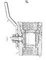
- a ball valve comprises a valve casing 1 having an opening at each end thereof, a ball 2 accommodatedin the valve casing 1 centrally thereof, valve seats 3, 4 disposed on opposite sides of the ball 2, and a valve stem 6 having a handle 5.
- the valve casing 1 comprises a valve body 7 provided with a socket 9, and a pipe connecting bushing 11.
- the socket 9 is provided with an internally threaded portion 8 and has an inside diameter for permitting the passage of the ball 2.
- the bushing 11 has an externally threaded portion 10 screwed in the socket 9.
- the outer peripheral surface 12 of the forward end of the bushing 11 has a smaller diameter than the externally threaded portion 10 to provide a movable circular step 13.
- the valve body 7 is internally formed with a stationary circular step 14 opposed to, and spaced apart from, the movable circular step 13.
- An annular space 16 is defined by both the circular steps 13, 14, the bushing end outer peripheral surface 12 and the valve body inner surface 15 opposed to the surface 12.
- the annular space 16 has accommodated therein a sealing ring 17 of tetrafluoroethylene which is so shaped in cross section as to almost completely fill up the space 16.
- the outer peripheral surface 12 forms an obtuse angle with the movable circular step 13, while the valve body inner surface 15 makes a right angle with the stationary circular step 14.
- the sealing ring 17 is trapezoidal in cross section.
- the movable circular step 13 and the sealing ring 17 have tapered surfaces in contact with each other.
- the sealing ring 17 is clamped between the movable step 13 and the stationary step 14 when the bushing 11 is screwed into the socket 9 of the valve body 7.
- the reaction of the sealing ring 17 resulting from the clamping pressure acts on both the steps 13, 14 and also on the bushing end outer surface 12 and the valve body inner surface 15 opposed to the surface 12.
- the movable circular step 13 and the sealing ring 17 have the tapered surfaces where they are in contact with each other, consequently producing a wedging effect.
- Fig. 3 shows a modification of the essential part of the above ball valve.
- the bushing end outer peripheral surface 12 and the movable circular step 22, as well as the valve body inner surface 15 and the stationary circular step 14, form a right angle.
- a sealing ring 23 comprises a pair of divided segments 23a, 23b which are wedge-shaped and which have slanting surfaces in contact with each other.
- the sealing ring 23 is clamped between the movable step 22 and the stationary step 14 when a bushing 21 is screwed into the socket 9 of the valve body 7.
- the reaction of the sealing ring 23 resulting from the clamping pressure acts on the steps 22, 14 and also on the bushing end outer surface 12 and the valve body inner surface 15 opposed to the surface 12 as is the case with the embodiment shown in Figs. 1 and 2.
- the sealing ring 23 is divided into the segments 23a, 23b which are wedge-shaped in cross section and are in contact with each other at the slanting surfaces, a greater wedging effect can be obtained than is available with the foregoing embodiment.
- the material for forming the sealing ring is not limited to tetrafluoroethylene but can be other suitable synthetic resin. Also usable are rubbers, such as acrylonitrile-butadiene rubber, urethane rubber, silicone rubber and fluoroelastomer, and metals, such as copper, aluminum and nickel.
Landscapes
- Engineering & Computer Science (AREA)
- General Engineering & Computer Science (AREA)
- Mechanical Engineering (AREA)
- Taps Or Cocks (AREA)
- Valve Housings (AREA)
- Lift Valve (AREA)
Applications Claiming Priority (2)
| Application Number | Priority Date | Filing Date | Title |
|---|---|---|---|
| JP151753/83 | 1983-09-29 | ||
| JP1983151753U JPS6058973U (ja) | 1983-09-29 | 1983-09-29 | ボ−ル弁 |
Publications (2)
| Publication Number | Publication Date |
|---|---|
| EP0139246A2 true EP0139246A2 (de) | 1985-05-02 |
| EP0139246A3 EP0139246A3 (de) | 1985-10-30 |
Family
ID=15525537
Family Applications (1)
| Application Number | Title | Priority Date | Filing Date |
|---|---|---|---|
| EP84111443A Withdrawn EP0139246A3 (de) | 1983-09-29 | 1984-09-26 | Kugelhahn |
Country Status (4)
| Country | Link |
|---|---|
| EP (1) | EP0139246A3 (de) |
| JP (1) | JPS6058973U (de) |
| KR (1) | KR890002509Y1 (de) |
| CA (1) | CA1256084A (de) |
Cited By (3)
| Publication number | Priority date | Publication date | Assignee | Title |
|---|---|---|---|---|
| WO2002063189A1 (de) * | 2001-02-06 | 2002-08-15 | Imt Armaturen Ag | Regel- oder sperrventil |
| CN104455535A (zh) * | 2014-12-08 | 2015-03-25 | 浙江中信阀门有限公司 | 大口径自带监测功能的天然气专用双向密封偏心球阀 |
| CN108278382A (zh) * | 2018-04-10 | 2018-07-13 | 博莱阀门(常州)有限公司 | 一种浮动球阀 |
Family Cites Families (8)
| Publication number | Priority date | Publication date | Assignee | Title |
|---|---|---|---|---|
| US1291631A (en) * | 1917-03-29 | 1919-01-14 | Luther T Pearsall | Cut-off valve. |
| US2981284A (en) * | 1959-07-24 | 1961-04-25 | J L Putnam Company Inc | Ball valve |
| DE1450470A1 (de) * | 1964-11-18 | 1968-12-05 | Acf Ind Inc | Kugelschieberventil |
| CH474011A (de) * | 1968-10-18 | 1969-06-15 | Wullschleger Erwin | Klemmverschraubung zum Verbinden von Rohren, insbesondere verzinkten Eisenrohren, sowie Verwendung derselben |
| DE6920341U (de) * | 1969-05-20 | 1969-08-28 | Boehler & Co Ag Wien I Geb | Dichtung, insbesondere zur abdichtung von zwischen gehaeussteilen dampfbeheizter ventile vorhandenen spalten |
| JPS483158U (de) * | 1971-05-31 | 1973-01-16 | ||
| NZ180986A (en) * | 1975-05-29 | 1978-03-06 | Richards & Co B C | Ball valve seal assembly |
| NL181136C (nl) * | 1976-08-06 | 1987-06-16 | Richards & Co B C | Kogelafsluiter. |
-
1983
- 1983-09-29 JP JP1983151753U patent/JPS6058973U/ja active Pending
-
1984
- 1984-09-26 KR KR2019840009475U patent/KR890002509Y1/ko not_active Expired
- 1984-09-26 EP EP84111443A patent/EP0139246A3/de not_active Withdrawn
- 1984-09-28 CA CA000464251A patent/CA1256084A/en not_active Expired
Cited By (3)
| Publication number | Priority date | Publication date | Assignee | Title |
|---|---|---|---|---|
| WO2002063189A1 (de) * | 2001-02-06 | 2002-08-15 | Imt Armaturen Ag | Regel- oder sperrventil |
| CN104455535A (zh) * | 2014-12-08 | 2015-03-25 | 浙江中信阀门有限公司 | 大口径自带监测功能的天然气专用双向密封偏心球阀 |
| CN108278382A (zh) * | 2018-04-10 | 2018-07-13 | 博莱阀门(常州)有限公司 | 一种浮动球阀 |
Also Published As
| Publication number | Publication date |
|---|---|
| EP0139246A3 (de) | 1985-10-30 |
| JPS6058973U (ja) | 1985-04-24 |
| CA1256084A (en) | 1989-06-20 |
| KR890002509Y1 (ko) | 1989-04-29 |
| KR850009609U (ko) | 1985-12-05 |
Similar Documents
| Publication | Publication Date | Title |
|---|---|---|
| US4109923A (en) | Pipe joint | |
| US3759552A (en) | Hydraulic coupling with metallic sealing member | |
| US4744572A (en) | All-metal, valve sealing mechanism | |
| EP0049573B1 (de) | Kugelhahn | |
| US3883112A (en) | Plug valve having composite seat element | |
| US4580788A (en) | Split ring sealing device for high pressure service | |
| US5490537A (en) | Prosthesis air valve assembly and tool therefor | |
| US2641381A (en) | Sealing means for pressure vessels | |
| US4817668A (en) | Integral metal seal for hydraulic coupling | |
| US3206216A (en) | Fluid pressure seal assemblage | |
| US4415170A (en) | Double toric sealing ring | |
| KR910012589A (ko) | 유니온 조인트 | |
| US4235418A (en) | Ball valve having metal seat rings | |
| GB1577807A (en) | Ball valves and metallic valve seats and ball-and-seat assemblies therefor | |
| US4138183A (en) | Cryogenic connector | |
| US4482129A (en) | All metal valve structure for gas systems | |
| ES291638Y (es) | Perfeccionamientos en una empaquetadura de estaquidad para ion. | |
| EP0139246A2 (de) | Kugelhahn | |
| US4150836A (en) | Backed boss seal fitting | |
| DE3067355D1 (en) | Valve for cryogenic service and seal therefor | |
| EP0176687A3 (en) | Sealing device for throttle valves | |
| JPH08135795A (ja) | シール装置 | |
| US3028183A (en) | Sealed ball joint for electrodes | |
| US3346233A (en) | Seating ring for valves for the control of fluids | |
| US3131953A (en) | Valve and means for attaching the same to a conduit |
Legal Events
| Date | Code | Title | Description |
|---|---|---|---|
| PUAI | Public reference made under article 153(3) epc to a published international application that has entered the european phase |
Free format text: ORIGINAL CODE: 0009012 |
|
| AK | Designated contracting states |
Designated state(s): AT BE CH DE FR GB IT LI NL SE |
|
| PUAL | Search report despatched |
Free format text: ORIGINAL CODE: 0009013 |
|
| AK | Designated contracting states |
Designated state(s): AT BE CH DE FR GB IT LI NL SE |
|
| 17P | Request for examination filed |
Effective date: 19851218 |
|
| 17Q | First examination report despatched |
Effective date: 19860425 |
|
| STAA | Information on the status of an ep patent application or granted ep patent |
Free format text: STATUS: THE APPLICATION IS DEEMED TO BE WITHDRAWN |
|
| 18D | Application deemed to be withdrawn |
Effective date: 19860906 |
|
| RIN1 | Information on inventor provided before grant (corrected) |
Inventor name: OGAWA, HIROSHI Inventor name: MESE, HISAYOSHI |