EP0139287A2 - Transporteur sans fin - Google Patents
Transporteur sans fin Download PDFInfo
- Publication number
- EP0139287A2 EP0139287A2 EP84112339A EP84112339A EP0139287A2 EP 0139287 A2 EP0139287 A2 EP 0139287A2 EP 84112339 A EP84112339 A EP 84112339A EP 84112339 A EP84112339 A EP 84112339A EP 0139287 A2 EP0139287 A2 EP 0139287A2
- Authority
- EP
- European Patent Office
- Prior art keywords
- chain
- rail
- conveying means
- conveyor
- segments
- Prior art date
- Legal status (The legal status is an assumption and is not a legal conclusion. Google has not performed a legal analysis and makes no representation as to the accuracy of the status listed.)
- Withdrawn
Links
Images


Classifications
-
- B—PERFORMING OPERATIONS; TRANSPORTING
- B65—CONVEYING; PACKING; STORING; HANDLING THIN OR FILAMENTARY MATERIAL
- B65G—TRANSPORT OR STORAGE DEVICES, e.g. CONVEYORS FOR LOADING OR TIPPING, SHOP CONVEYOR SYSTEMS OR PNEUMATIC TUBE CONVEYORS
- B65G17/00—Conveyors having an endless traction element, e.g. a chain, transmitting movement to a continuous or substantially-continuous load-carrying surface or to a series of individual load-carriers; Endless-chain conveyors in which the chains form the load-carrying surface
- B65G17/30—Details; Auxiliary devices
- B65G17/38—Chains or like traction elements; Connections between traction elements and load-carriers
- B65G17/385—Chains or like traction elements; Connections between traction elements and load-carriers adapted to follow three-dimensionally curved paths
-
- B—PERFORMING OPERATIONS; TRANSPORTING
- B65—CONVEYING; PACKING; STORING; HANDLING THIN OR FILAMENTARY MATERIAL
- B65G—TRANSPORT OR STORAGE DEVICES, e.g. CONVEYORS FOR LOADING OR TIPPING, SHOP CONVEYOR SYSTEMS OR PNEUMATIC TUBE CONVEYORS
- B65G21/00—Supporting or protective framework or housings for endless load-carriers or traction elements of belt or chain conveyors
- B65G21/20—Means incorporated in, or attached to, framework or housings for guiding load-carriers, traction elements or loads supported on moving surfaces
- B65G21/22—Rails or the like engaging sliding elements or rollers attached to load-carriers or traction elements
-
- B—PERFORMING OPERATIONS; TRANSPORTING
- B65—CONVEYING; PACKING; STORING; HANDLING THIN OR FILAMENTARY MATERIAL
- B65G—TRANSPORT OR STORAGE DEVICES, e.g. CONVEYORS FOR LOADING OR TIPPING, SHOP CONVEYOR SYSTEMS OR PNEUMATIC TUBE CONVEYORS
- B65G39/00—Rollers, e.g. drive rollers, or arrangements thereof incorporated in roller-ways or other types of mechanical conveyors
- B65G39/10—Arrangements of rollers
- B65G39/20—Arrangements of rollers attached to moving belts or chains
-
- F—MECHANICAL ENGINEERING; LIGHTING; HEATING; WEAPONS; BLASTING
- F16—ENGINEERING ELEMENTS AND UNITS; GENERAL MEASURES FOR PRODUCING AND MAINTAINING EFFECTIVE FUNCTIONING OF MACHINES OR INSTALLATIONS; THERMAL INSULATION IN GENERAL
- F16C—SHAFTS; FLEXIBLE SHAFTS; ELEMENTS OR CRANKSHAFT MECHANISMS; ROTARY BODIES OTHER THAN GEARING ELEMENTS; BEARINGS
- F16C29/00—Bearings for parts moving only linearly
- F16C29/04—Ball or roller bearings
-
- F—MECHANICAL ENGINEERING; LIGHTING; HEATING; WEAPONS; BLASTING
- F16—ENGINEERING ELEMENTS AND UNITS; GENERAL MEASURES FOR PRODUCING AND MAINTAINING EFFECTIVE FUNCTIONING OF MACHINES OR INSTALLATIONS; THERMAL INSULATION IN GENERAL
- F16C—SHAFTS; FLEXIBLE SHAFTS; ELEMENTS OR CRANKSHAFT MECHANISMS; ROTARY BODIES OTHER THAN GEARING ELEMENTS; BEARINGS
- F16C33/00—Parts of bearings; Special methods for making bearings or parts thereof
- F16C33/30—Parts of ball or roller bearings
- F16C33/38—Ball cages
- F16C33/3812—Ball cages formed of interconnected segments, e.g. chains
-
- B—PERFORMING OPERATIONS; TRANSPORTING
- B65—CONVEYING; PACKING; STORING; HANDLING THIN OR FILAMENTARY MATERIAL
- B65G—TRANSPORT OR STORAGE DEVICES, e.g. CONVEYORS FOR LOADING OR TIPPING, SHOP CONVEYOR SYSTEMS OR PNEUMATIC TUBE CONVEYORS
- B65G2201/00—Indexing codes relating to handling devices, e.g. conveyors, characterised by the type of product or load being conveyed or handled
- B65G2201/02—Articles
Definitions
- the invention relates to a continuous conveyor according to the preamble of claim 1.
- Such a continuous conveyor is known for example from FR-PS 2 064 235 in its application as a spreader for textile webs.
- the raceways namely both the conveyor-side and the rail-side raceways have an arcuate cross-section, the radius of which corresponds to the radius of the balls.
- the proposed continuous conveyor has the features specified in the characterizing part of patent claim 1.
- the endless conveying means with the dash-dotted line 11 and a rail guiding the conveying means with the solid lines 12 running on both sides of the line 11 are indicated.
- the funding 11 is equipped with only schematically indicated drivers 13. These drivers can be controlled grippers or protruding stops, for example.
- the conveyor-active strand (top in FIG. 1) of the continuous conveyor 10 begins following an infeed conveyor 14 in the form of a ribbon conveyor, is flanked on both sides by slide rails 15 which serve to support piece goods (not shown) captured by the drivers 13, and finally ends at a conveyor 16.
- baffles 19 are arranged in the region of the active conveyor side to the side of the slide rails 15 and at least on the outside of the respective curve section in order to cause the conveyed piece goods to follow the course of the continuous conveyor 10.
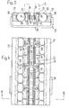
- the conveying means is formed by a roller guide chain 20.
- This has rollers 21 arranged at regular intervals from one another and penetrated by pins, which are connected in pairs to one another by means of inner tabs 22.
- Each pair of these rollers 21 is connected to the adjacent pair by outer plates 23, the plates 22 and 23 also being rotatable about the pins passing through the rollers 21.
- Every second of the inner plates 22 is provided with an extension 24 protruding at right angles from the chain 20 and bent in an L-shape, to each of which a guide segment 25 is anchored by means of a screw.
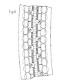
- Each guide segment 25 has a raceway 26, the profile of which has the shape of a truncated V. It can be seen from FIG. 4 that there is a small distance between successive guide segments 25.
- the rail 12 has a guide track 27, which describes the entire course of the continuous conveyor, on both sides of the chain.
- these guideways 27 On their sides facing the guide segments 25, these guideways 27 have a raceway 28, the profile of which is similar to the profile of the raceways 26 in the guide segments 25.
- the two guideways 27 are connected to one another by spacers or brackets 29 arranged at regular intervals and anchored to the guideways 27 themselves.
- each guide segment 25 on one side of the chain 20 and between the guideway 27 and the guide segments 25 on the other side of the chain there are a number of balls 30 each, which move when the chain 20 moves in the raceways 26 and pass on 28.
- the balls 30 move in the same direction as the chain 20, but only at about half the speed if slip-free rolling is assumed.
- the length of the guide segments 25 is advantageously more than twice the diameter of the ball 30, since this ensures that each guide segment 25 always abuts at least two balls 30.
- ball cages or spacers could additionally be provided in order to keep the balls 30 at a well-defined distance from one another and thus to collide with one another during operation to prevent neighboring balls.
- FIG. 5 differs from that of FIGS. 3 and 4 in that the guide segments 25 on one side of the roller chain 20 are offset with respect to the guide segments 25 on the other side by an amount which corresponds to approximately half their length .
- adjacent guide segments 25 are loosely coupled to one another by pins 31 in FIG. 5.
- the pins 31 engage both with circumferential and axial play in bores in the mutually facing end faces of the guide segments 25.
- a biegsa can also be used to couple adjacent guide segments between them Mes and elastically deformable element, for example made of rubber.
- the coupling of the guide segments 25 to one another essentially serves to keep their raceways 26 somewhat aligned with one another.
- the continuous conveyor thanks to the small distance between the successive guide segments 25 and the inevitable play of the connecting tabs on the bolts or bushings of the roller chain 20, can also have a curved course in a plane that is perpendicular to that plane , which is given, for example, by a sprocket engaging in the roller chain.
- each link of the link chain 32 has two identical link halves 33, 34 which are screwed together (FIG. 9). Both link halves have at one end a ring eyelet 36 or 37 enclosing an articulated ball 35 "equatorially", and at their other end a ball socket 38 or 39 that grips the next articulated ball 35 in the manner of "pole caps". Between the ring eyelet 36 or 37 and the ball socket 38 or 39, each of the link halves 33, 34 has a continuous opening 40 or 41, which has a square, slightly converging cross section. This continuous opening serves to drive the chain 32, for which purpose a chain wheel 42 can serve, as is indicated by dash-dotted lines in FIG. 7.
- the side flanks of the link halves 33, 34 are profiled, as can be seen in FIG. 8, so that when the link halves are screwed together, the chain-side raceway 26 is formed for the balls 30. Again, the length of the link halves 33, 34 is selected such that the raceways 26 are longer than twice the diameter of the balls 30.
- the rail-side raceways 28 are formed in this embodiment in the mutually facing sides of the legs of the here substantially U-shaped and one-piece rail 12. Since the chain 32 can follow any course spatially and can also be twisted, the continuous conveyor according to FIGS. 7 to 9 is particularly suitable for spatially complicated courses.
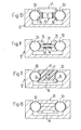
- the conveying means is again formed by a roller chain 20.
- the outer connecting lugs are replaced by a bracket 43 spanning the rollers 21 in a portal-like manner, the legs of which serve as an outer connecting lug and are also profiled in such a way that they at the same time form a bottom-side barrel 26 for the balls 30.
- the bracket 43 instead of the bracket 43, as shown in FIG. 10, to give only the outer connecting links the shape of a truncated V which is open towards the side of the chain 20, so that each of these connecting links is in itself a section of the chain-side raceway 26 form. In other words, it is possible to omit the part of the same located between the dotted lines in the bracket 43 in FIG.
- the conveying means is also formed by the roller chain 20.
- the guide segments 25 are not fastened here to the connecting plates between the rollers 21, but on a bolt 44 projecting on both sides of the chain, on which one of the rollers 21 and the respective connecting plates of the roller chain are rotatably mounted.
- the conveying means is formed by a toothed belt 45.
- This has a toothing designated by 46 for the drive and on its narrow sides each have a fillet which forms the raceway 26 for the balls 30.
- the toothed belt 45 can, as shown, a soul, e.g. have in the form of a wire rope 47.
- the toothed belt 45 can be constructed from two profile belts which are intimately connected to one another, as indicated by dashed lines in FIG. 12.
- a massive "toothed belt” 48 made of a flexible plastic is provided as the conveying means.
- This can be endless or made of individual flexible profile bars that abut one another on the end face, the cross section of which corresponds to the cross section of the toothed belt 45 of FIG. 12.
- the conveying means is a composite structure which is constructed as follows.
- strings made of a tensile material similar to the soul 47 in Fig. 12
- a pearl cord a plurality of transverse to the or Strings extending slats drawn, the outline of which corresponds approximately to the cross section of the belts 45 and 48 shown in FIGS. 12 and 13.
- the end faces of these lamellae that is to say the faces perpendicular to the strings or strings, are advantageously somewhat cambered and abut one another.
- the conveyor-side track 26 is not divided into comparatively long segments, as in the embodiments of FIGS. 3 to 11, and also not, as in FIGS. 12 and 13, practically uninterrupted, rather the track on the conveyor side is in the laminated conveyor of this embodiment a large number of segments, which are very short compared to the dimensions of the balls, so that during operation each ball is in contact with only one of these segments for a very short time and, in the rest, rolls smoothly over the laminated track.
- This embodiment also has the advantage that the continuous conveyor can be given any spatial course which, if the associated rail 12 is shaped accordingly, can also have twists.
Landscapes
- Engineering & Computer Science (AREA)
- Mechanical Engineering (AREA)
- General Engineering & Computer Science (AREA)
- Framework For Endless Conveyors (AREA)
- Specific Conveyance Elements (AREA)
- Attitude Control For Articles On Conveyors (AREA)
- Rollers For Roller Conveyors For Transfer (AREA)
Applications Claiming Priority (2)
| Application Number | Priority Date | Filing Date | Title |
|---|---|---|---|
| CH5824/83 | 1983-10-27 | ||
| CH582483A CH663773A5 (de) | 1983-10-27 | 1983-10-27 | Stetigfoerderer. |
Publications (2)
| Publication Number | Publication Date |
|---|---|
| EP0139287A2 true EP0139287A2 (fr) | 1985-05-02 |
| EP0139287A3 EP0139287A3 (fr) | 1985-06-19 |
Family
ID=4299908
Family Applications (1)
| Application Number | Title | Priority Date | Filing Date |
|---|---|---|---|
| EP84112339A Withdrawn EP0139287A3 (fr) | 1983-10-27 | 1984-10-13 | Transporteur sans fin |
Country Status (3)
| Country | Link |
|---|---|
| EP (1) | EP0139287A3 (fr) |
| JP (1) | JPS60112508A (fr) |
| CH (1) | CH663773A5 (fr) |
Cited By (3)
| Publication number | Priority date | Publication date | Assignee | Title |
|---|---|---|---|---|
| WO2005087627A1 (fr) * | 2004-03-18 | 2005-09-22 | Wrh Walter Reist Holding Ag | Dispositif de transport roulant |
| WO2006094423A1 (fr) * | 2005-03-11 | 2006-09-14 | Wrh Walter Reist Holding Ag | Dispositif de transport, corps de roulement et corps de transport |
| EP2210832A1 (fr) * | 2005-03-11 | 2010-07-28 | WRH Walter Reist Holding AG | Dispositif de transport et roulement à billes |
Families Citing this family (3)
| Publication number | Priority date | Publication date | Assignee | Title |
|---|---|---|---|---|
| DE8914973U1 (de) * | 1989-12-21 | 1990-05-10 | Konstruktions- und Entwicklungsbüro W. Augenstein, 89312 Günzburg | Scharnierbandkettentransport |
| CH704134A1 (de) | 2010-11-26 | 2012-05-31 | Ferag Ag | Fördersystem, förderelement und führungskanal. |
| JP6472961B2 (ja) * | 2014-08-13 | 2019-02-20 | 日本電子株式会社 | 検体ラック搬送ユニット及び自動分析システム |
Family Cites Families (2)
| Publication number | Priority date | Publication date | Assignee | Title |
|---|---|---|---|---|
| BE757062A (fr) * | 1969-10-10 | 1971-03-16 | Proctor & Schwartz Inc | Transporteur a billes circulantes |
| JPS531751A (en) * | 1976-06-29 | 1978-01-10 | Olympus Optical Co | Pole race |
-
1983
- 1983-10-27 CH CH582483A patent/CH663773A5/de not_active IP Right Cessation
-
1984
- 1984-10-13 EP EP84112339A patent/EP0139287A3/fr not_active Withdrawn
- 1984-10-26 JP JP22422684A patent/JPS60112508A/ja active Pending
Cited By (9)
| Publication number | Priority date | Publication date | Assignee | Title |
|---|---|---|---|---|
| WO2005087627A1 (fr) * | 2004-03-18 | 2005-09-22 | Wrh Walter Reist Holding Ag | Dispositif de transport roulant |
| EP2233411A3 (fr) * | 2004-03-18 | 2010-10-06 | WRH Walter Reist Holding AG | Dispositif de transport roulant |
| US7870948B2 (en) | 2004-03-18 | 2011-01-18 | Wrh Walter Reist Holding Ag | Rolling conveying device |
| WO2006094423A1 (fr) * | 2005-03-11 | 2006-09-14 | Wrh Walter Reist Holding Ag | Dispositif de transport, corps de roulement et corps de transport |
| EP2210832A1 (fr) * | 2005-03-11 | 2010-07-28 | WRH Walter Reist Holding AG | Dispositif de transport et roulement à billes |
| EP2210831A1 (fr) * | 2005-03-11 | 2010-07-28 | WRH Walter Reist Holding AG | Dispositif de transport et élément de transport |
| US7918331B2 (en) | 2005-03-11 | 2011-04-05 | Wrh Walter Reist Holding Ag | Transport device, rolling body and transport body |
| US8079463B2 (en) | 2005-03-11 | 2011-12-20 | Wrh Walter Reist Holding Ag | Conveying device, rolling body and conveying body |
| AU2006222472B2 (en) * | 2005-03-11 | 2012-07-05 | Wrh Walter Reist Holding Ag | Transport device, rolling body and transport body |
Also Published As
| Publication number | Publication date |
|---|---|
| JPS60112508A (ja) | 1985-06-19 |
| EP0139287A3 (fr) | 1985-06-19 |
| CH663773A5 (de) | 1988-01-15 |
Similar Documents
| Publication | Publication Date | Title |
|---|---|---|
| EP0635441B1 (fr) | Chaîne transporteuse | |
| EP2928807A1 (fr) | Roue à chaîne de convoyeur ou roue à chaîne de renvoi à durée de vie accrue | |
| DE19616907C2 (de) | Förderbahn für Stückgut, insbesondere für Gepäck-Behälter | |
| EP1342928B1 (fr) | Palier linéaire à billes | |
| EP1092656B1 (fr) | Dispositif de transport | |
| EP1412265B1 (fr) | Element de courbe capable de retenir des articles, pour un systeme de transfert | |
| DE2754918C2 (de) | Einrichtung zum Herstellen gleicher Abstände zwischen Stückgütern auf einem Transportband | |
| DE3432042C2 (fr) | ||
| EP0139287A2 (fr) | Transporteur sans fin | |
| EP2256070B1 (fr) | Dispositif de convoyeur de bande | |
| DE2620864A1 (de) | Waelzelement fuer linearbewegungen | |
| DE102014102873A1 (de) | Förderer zum Sortieren von Stückgütern | |
| DE2031903C3 (de) | Gliederhandlauf für Fahrtreppen oder Personenförderbänder | |
| DE102005041689B4 (de) | Energieführungskette | |
| DE2025667C3 (de) | Endloser Kettenförderer | |
| EP0937663A1 (fr) | Dispositif d'appui | |
| DE2264865B2 (de) | Gliederförderband aus mehreren gelenkig miteinander verbundenen metallischen Plattengliedern | |
| DE3304568C2 (de) | Fördervorrichtung für den Transport von Lasten | |
| EP0649729B1 (fr) | Dispositif de transport avec bande transporteuse guidée le long d'un tournant | |
| DE2622813C2 (de) | Fördervorrichtung | |
| EP0592893B1 (fr) | Brosse avec porte-soies flexible sans fin | |
| DE974815C (de) | Plattenbandfoerderer | |
| CH714496A1 (de) | Fördervorrichtung. | |
| EP1705770A1 (fr) | Méthode d'emploi d'une chaîne de transport d'énergie et goulotte de maintien pour la mise en oeuvre de cette méthode | |
| DE2751081A1 (de) | Foerdervorrichtung fuer stueckgut, insbesondere weiche fuer eine foerderanlage |
Legal Events
| Date | Code | Title | Description |
|---|---|---|---|
| PUAI | Public reference made under article 153(3) epc to a published international application that has entered the european phase |
Free format text: ORIGINAL CODE: 0009012 |
|
| PUAL | Search report despatched |
Free format text: ORIGINAL CODE: 0009013 |
|
| AK | Designated contracting states |
Designated state(s): AT CH DE FR GB IT LI NL SE |
|
| AK | Designated contracting states |
Designated state(s): AT CH DE FR GB IT LI NL SE |
|
| 17P | Request for examination filed |
Effective date: 19850429 |
|
| STAA | Information on the status of an ep patent application or granted ep patent |
Free format text: STATUS: THE APPLICATION HAS BEEN WITHDRAWN |
|
| 18W | Application withdrawn |
Withdrawal date: 19860312 |
|
| RIN1 | Information on inventor provided before grant (corrected) |
Inventor name: REIST, WALTER |