EP0139292A2 - Ortungsgerät für ein Fahrzeug - Google Patents
Ortungsgerät für ein Fahrzeug Download PDFInfo
- Publication number
- EP0139292A2 EP0139292A2 EP84112406A EP84112406A EP0139292A2 EP 0139292 A2 EP0139292 A2 EP 0139292A2 EP 84112406 A EP84112406 A EP 84112406A EP 84112406 A EP84112406 A EP 84112406A EP 0139292 A2 EP0139292 A2 EP 0139292A2
- Authority
- EP
- European Patent Office
- Prior art keywords
- mobile system
- navigation apparatus
- image
- pattern
- information
- Prior art date
- Legal status (The legal status is an assumption and is not a legal conclusion. Google has not performed a legal analysis and makes no representation as to the accuracy of the status listed.)
- Granted
Links
Images



Classifications
-
- G—PHYSICS
- G01—MEASURING; TESTING
- G01S—RADIO DIRECTION-FINDING; RADIO NAVIGATION; DETERMINING DISTANCE OR VELOCITY BY USE OF RADIO WAVES; LOCATING OR PRESENCE-DETECTING BY USE OF THE REFLECTION OR RERADIATION OF RADIO WAVES; ANALOGOUS ARRANGEMENTS USING OTHER WAVES
- G01S3/00—Direction-finders for determining the direction from which infrasonic, sonic, ultrasonic or electromagnetic waves, or particle emission, not having a directional significance, are being received
- G01S3/78—Direction-finders for determining the direction from which infrasonic, sonic, ultrasonic or electromagnetic waves, or particle emission, not having a directional significance, are being received using electromagnetic waves other than radio waves
- G01S3/782—Systems for determining direction or deviation from predetermined direction
- G01S3/785—Systems for determining direction or deviation from predetermined direction using adjustment of orientation of directivity characteristics of a detector or detector system to give a desired condition of signal derived from that detector or detector system
- G01S3/786—Systems for determining direction or deviation from predetermined direction using adjustment of orientation of directivity characteristics of a detector or detector system to give a desired condition of signal derived from that detector or detector system the desired condition being maintained automatically
- G01S3/7864—T.V. type tracking systems
- G01S3/7865—T.V. type tracking systems using correlation of the live video image with a stored image
-
- G—PHYSICS
- G05—CONTROLLING; REGULATING
- G05D—SYSTEMS FOR CONTROLLING OR REGULATING NON-ELECTRIC VARIABLES
- G05D1/00—Control of position, course, altitude or attitude of land, water, air or space vehicles, e.g. using automatic pilots
- G05D1/02—Control of position or course in two dimensions
- G05D1/021—Control of position or course in two dimensions specially adapted to land vehicles
- G05D1/0231—Control of position or course in two dimensions specially adapted to land vehicles using optical position detecting means
- G05D1/0246—Control of position or course in two dimensions specially adapted to land vehicles using optical position detecting means using a video camera in combination with image processing means
-
- G—PHYSICS
- G05—CONTROLLING; REGULATING
- G05D—SYSTEMS FOR CONTROLLING OR REGULATING NON-ELECTRIC VARIABLES
- G05D1/00—Control of position, course, altitude or attitude of land, water, air or space vehicles, e.g. using automatic pilots
- G05D1/02—Control of position or course in two dimensions
- G05D1/021—Control of position or course in two dimensions specially adapted to land vehicles
- G05D1/0268—Control of position or course in two dimensions specially adapted to land vehicles using internal positioning means
- G05D1/027—Control of position or course in two dimensions specially adapted to land vehicles using internal positioning means comprising intertial navigation means, e.g. azimuth detector
-
- G—PHYSICS
- G05—CONTROLLING; REGULATING
- G05D—SYSTEMS FOR CONTROLLING OR REGULATING NON-ELECTRIC VARIABLES
- G05D1/00—Control of position, course, altitude or attitude of land, water, air or space vehicles, e.g. using automatic pilots
- G05D1/02—Control of position or course in two dimensions
- G05D1/021—Control of position or course in two dimensions specially adapted to land vehicles
- G05D1/0268—Control of position or course in two dimensions specially adapted to land vehicles using internal positioning means
- G05D1/0272—Control of position or course in two dimensions specially adapted to land vehicles using internal positioning means comprising means for registering the travel distance, e.g. revolutions of wheels
-
- G—PHYSICS
- G05—CONTROLLING; REGULATING
- G05D—SYSTEMS FOR CONTROLLING OR REGULATING NON-ELECTRIC VARIABLES
- G05D1/00—Control of position, course, altitude or attitude of land, water, air or space vehicles, e.g. using automatic pilots
- G05D1/02—Control of position or course in two dimensions
- G05D1/021—Control of position or course in two dimensions specially adapted to land vehicles
- G05D1/0268—Control of position or course in two dimensions specially adapted to land vehicles using internal positioning means
- G05D1/0274—Control of position or course in two dimensions specially adapted to land vehicles using internal positioning means using mapping information stored in a memory device
Definitions
- the present invention relates to a navigation apparatus for mobile systems such as robots, and more particularly to a navigation apparatus which can move a mobile system to a destination by understanding the surroundings and in adaptation to the environment.
- a navigation apparatus which autonomously guides a robot to a desired destination.
- the navigation apparatus there is a system which employs observed image information for guidance information (Proceeding of 24th conference on remote systems technology, IS 76, pp. 196 - 218).
- This navigation apparatus employing the image information is such that an image obtained with a television camera or the like is processed to extract the feature points of the image, that determine the three-dimensional arrangement of an object including directions, distances etc. is computed on the basis of the arrangement of the feature points, and that a distance to the object is detected on the basis of the computation so as to find a guidance signal which includes an steering, a speed etc. and with which the mobile system is guided.
- the prior-art navigation apparatus has been used under a well-ordered situation in which vibrations hardly develop or a situation in which a fixed target object can be always utilized or a recognition pattern is comprised. Moreover, it has been inevitable to run the mobile system at low speed so that the surroundings can be sufficiently recognized. Consequently, the aforementioned navigation apparatus is unsuited for application to a mobile system which moves at high speed in general environments.
- the present invention has been made in view of the above drawbacks, and has for its object to provide a navigation apparatus which can move and guide a mobile system at high speed in general environments.
- the present invention for accomplishing the object consists, in a navigation apparatus for guiding a mobile system along a predetermined path, in comprising means to detect a path movement of the mobile system, memory means to deliver a predictive pattern measurable at a particular position on the basis of positional information of the mobile system detected by the detection means, vision means to measure an actual environment and to detect an actual image thereof, at least one image processor which extracts a observed feature pattern from the observed image obtained with the vision means, and guidance control means to compare the observed feature pattern from the image processor with the predicted pattern and to deliver a guidance signal for the mobile system.
- the navigation apparatus of the present invention computes a guidance signal for a mobile system by estimating the position of the mobile system on the basis of an image taken by means of a camera carried on the mobile system, under the premise that information items on an environment model and a moving path have been already given.
- An algorithm for producing the guidance signal will be explained more in detail. As illustrated in Fig. 1, the pre-estimated value X O of the current position of the mobile system is found on the basis of the rotational magnitude, the steering magnitude etc. of the driving motor of the mobile system.
- a prediction image f p corresponding to the pre-estimated value is generated drawn using environment model information K and a predictor L.
- the predicted image fp and a measured image f m are compared to find their image error E f , which a converter M converts into a position error E X , on the basis of which the pre-estimated value X o is compensated for to obtain an estimated positional value X.
- the mobile system is guided to a desired path on the basis of the estimated positional value X. Information for bringing the current position of the mobile system into agreement with the present path is available as the residual E X of the position estimation throughout the sampling of the television camera.
- dynamic position estimation means in the comparison between the predicted image f p and the observed image f m for the positional error conversion in the operating flow of obtaining the guidance signal states before, dynamic position estimation means is employed which is acquired by introducing a dynamical model between the patterns of these images.
- the position estimation means is such that a pattern A and a pattern B are arranged within an identical space S and that these patterns A and B are provided with respective operators M A and M B , either or both of which is/are manipulated to move the pattern/patterns so as to decrease an interaction working between the patterns A and B, whereby the pattern matching is dynamically executed.
- the space S is a image screen and that the patterns A and B are binary images.
- the pattern A is assumed a pattern based on the measured image
- the pattern B is assumed a pattern based on the predicted image produced in accordance with the environment model K.
- This adaptation rule is obtained by introducing a potential f A which is established on the space S by the pattern A.
- the potential f A can be evaluated by the following equation (1):
- ⁇ denotes a differential operator expressed by and y are parameters which express the spatial spread of the potential ⁇ A .
- X A is a characteristic function in the case of regarding the pattern A as a subset of the space A.
- a force F B to which the pattern B is subjected by the field of the potential ⁇ A of the pattern A on the space S described above can be evaluated by the following equation (2).
- equation (2) a force F B to which the pattern B is subjected by the field of the potential ⁇ A of the pattern A on the space S described above.
- X B denotes a characteristic function in the case of regarding the pattern B as being identical to a subset of the space S
- D a gradient operator, namely, a differential operator of .
- Equation (1) in the computation includes simultaneous equations of infinite dimensional equation
- equation of approximation (3) should favorably be used:
- a pattern matching mechanism made from the aforementioned equations (3) and (4) can be put into hardware by the use of an image memory and two sorts of regional arithmetic units.
- a mobile system 1 which is guided by the navigation apparatus of the present invention includes a vehicle mechanism 1A such as wheels or caterpillars and can move in a desired direction by means of a steering mechanism (not shown).
- the mobile system 1 includes a gyroscope 1B for detecting an azimuth and a detector or rotary encoder 1C for detecting the rotational magnitude of the vehicle mechanism lA, which offer information for predicting the position of the mobile system itself.
- the mobile system 1 includes a television camera 2 by which a situation in front of the mobile system is picked up as image information.
- the navigation apparatus of the present invention for guiding the mobile system 1 comprises a location detector 3 which detects the location of the mobile system 1 in the path thereof on the basis of information signals delivered from the gyroscope 1B and the rotary encoder 1C; a memory 4 which stores the estimative feature patterns of the environment which are estimated from the locations of the mobile system delivered from the location detector 3, for example, the linear patterns of the group of parallel lines of a staircase, the border between a corridor and a wall, a window, etc.
- an image processor 5 by which a observed image from the television camera 2 is processed into a plurality of feature patterns at the same time, while a feature pattern effective for a comparison is extracted; a comparator 6 which studies the coincidence between the effective observed feature pattern from the image processor 5 and the predictive characteristic pattern from the memory 4; and a guidance controller 7 which computes a guidance signal for the mobile system 1 in accordance with the result of the comparison of the comparator 6 between the observed feature pattern and the predicted feature pattern and which delivers the guidance signal to the mobile system 1.
- the guidance signal of the guidance controller 7 moves the mobile system 1 along the target path as stated above, and is also used as a signal for the position control of the mobile system.
- the guidance controller 7 comprises a potential computer 7A which computes the field of the potential ⁇ A acting between the predicted pattern and the observed pattern, and a matching force evaluator 7B which computes the gradient vector of the force F B of the observed pattern acting on the predicted pattern, the force being produced by the field of the potential ⁇ A .
- the computative contents of these arithmetic units 7A and 7B are executed in accordance with the foregoing principle of the present invention.
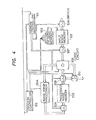
- the image processor 5 described above comprises an input image memory 501 which writes an input image therein; a pattern memory 502 which controls a write address for the input image memory 501, a processed image memory 503 which stores a processed image; an image array processor 504 which computes a compensation value that compensates for the gradation value of each of the picture elements of a given image on the basis of the gradation values of nearby picture elements; a hardware logic circuit 505 which executes a calculation for the data of a word length corresponding to the larger one of the gradation values of the picture elements of the input image memory 501 and the processed image memory 503; switches 506 - 509 which selectively deliver the values of the input image memory 501, processed image memory 503 and hardware logic circuit 505; a memory controller 511 which controls the switches 506 - 509; and a process controller 512 which controls the memory controller 511, pattern memory 502, hardware logic circuit 505, image array processor 504 and a switch 510.
- This image processor 5 can store the input image into the input image memory 501 by controlling the write address of the input image memory 501 by means of the pattern memory 502 as stated before. Therefore, it does not require any conversion computation, and it can execute the correction of a distortion, the conversion of an orientation, etc. in real time in respose to the image input signal. On this occasion, the content of the pattern memory 502 can be converted and set by the process controller 512. In addition, owing to the image array processor 504 and the hardware logic circuit 505 which are controlled by the process controller 512, this image processor 5 can be switched and used so as to have the functions of the potential computer 7A and the matching force evaluator 7B mentioned before.
- the information F 1 of the distorted staircase image F 1 is stored in the input image memory 501 as the information of a staircase image F 2 free from the distortions.
- the distortionless staircase image F 2 is processed into, for example, a horizontal line image F 3 corresponding to the steps of the staircase by means of the hardware logic circuit 505 as well as the image array processor 504.
- the horizontal line image F 3 is stored in the processed image memory 503.
- the information of the stored horizontal line image F 3 is delivered to the potential computer 7A of the guidance controller 7 by the switches 508 and 510.
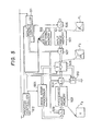
- the potential computer 7A can be implemented by the same arrangement as that of the image processor 5 shown in Fig. 4. Therefore, a circuit in Fig. 6 is treated as the arrangement of the potential computer 7A.
- the pattern memory 502 is set so as to perform the function of enlarging the specified region of the image information from the image processor 5 into the size of the whole screen, namely, the curving-out function.
- the image array processor 504 has its operation parameter set at isotropic diffusion.
- the hardware logic circuit 505 is set at an addition mode. Under this state, the information of the horizontal line image . F 3 from the image processor 5 shown in Fig.
- This information F 4 has, for example, only the information F 4 of one horizontal line stored into the input image memory 501 by the pattern memory 502 which is set at curving-out.
- This information F 4 is added in the hardware logic circuit 505 with an operation signal having the isotropic diffusion from the image array processor 504, to be converted into the information F 5 of a potential field which serves as one indicator of approach to the recognized information F 4'
- This information F 5 of the potential field is stored into the processed image memory 503, while it is delivered via the switch 510 to the matching force evaluator 7B connected therewith.
- the matching force evaluator 7B can be realized by the same arrangement as that of the image processor 5 shown in Fig. 4.
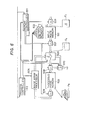
- the operations of the matching force evaluator 7B will be explained with reference to Fig. 7.
- the pattern memory 502 is set at a curving-out pattern memory
- the image array processor 504 is set at an operation parameter for computing a gradient in a matching force
- the hardware logic circuit 505 is set at an integration mode.
- the information F 5 of the potential field from the potential computer 7A has only a partial information F 6 thereof extracted by the pattern memory 502, whereupon the extracted information is stored into the input image memory 501.
- This information F 6 is applied to the image array processor 504 through the hardware logic circuit 505.
- the information F 6 is processed into the information F 7 of a gradient field which expresses the elements of the matching force.
- the information F 7 of the gradient preset field denotes a movement deviation relative to the f moving path of the mobile system 1. In other words, it denotes the position and sense to and in which the mobile system 1 ought to advance relative to the set moving path.
- This information F 7 of the gradient field is stored into the processed image memory 503, while it is delivered as the guidance signal of the mobile system 1 to this mobile system 1 shown in Fig. 3 through the switch 510.
- the guidance signal controls the steering mechanism of the mobile system 1.
- the mobile system 1 is guided along the predetermined path and can move toward its destination.
- the guidance signal is compared with the predicted location value of the mobile system from the mobile-system location predictor 3 so as to compensate for various errors involved in the running of the mobile system in the actual environment, for example, a running distance error caused by a slip, an uneven path surface or the like, and a steering error attributed to the unbalance of right and left motors or the drift of the gyroscope, and also to correct positional and directional errors at the point of time at which the running starts.
- the observed image obtained with the television camera has a plurality of feature patterns extracted at the same time by the image processors, and the best recognized one of the patterns is used as the index of navigation, so that navigation of high precision is possible. Furthermore, information which expresses the deviation between the observed feature pattern and a predicted feature pattern is detected in real time by the guidance controller 7.
- the present invention can be performed without employing the comparator 6.
- a mobile system can be moved at high speed in a wide range of general environments.
Landscapes
- Engineering & Computer Science (AREA)
- Physics & Mathematics (AREA)
- Radar, Positioning & Navigation (AREA)
- Remote Sensing (AREA)
- General Physics & Mathematics (AREA)
- Aviation & Aerospace Engineering (AREA)
- Automation & Control Theory (AREA)
- Multimedia (AREA)
- Electromagnetism (AREA)
- Computer Vision & Pattern Recognition (AREA)
- Navigation (AREA)
- Control Of Position, Course, Altitude, Or Attitude Of Moving Bodies (AREA)
- Image Analysis (AREA)
- Length Measuring Devices By Optical Means (AREA)
- Image Processing (AREA)
- Traffic Control Systems (AREA)
Applications Claiming Priority (2)
| Application Number | Priority Date | Filing Date | Title |
|---|---|---|---|
| JP192353/83 | 1983-10-17 | ||
| JP58192353A JPS6084610A (ja) | 1983-10-17 | 1983-10-17 | 誘導装置 |
Publications (3)
| Publication Number | Publication Date |
|---|---|
| EP0139292A2 true EP0139292A2 (de) | 1985-05-02 |
| EP0139292A3 EP0139292A3 (en) | 1987-04-22 |
| EP0139292B1 EP0139292B1 (de) | 1991-01-23 |
Family
ID=16289860
Family Applications (1)
| Application Number | Title | Priority Date | Filing Date |
|---|---|---|---|
| EP84112406A Expired - Lifetime EP0139292B1 (de) | 1983-10-17 | 1984-10-15 | Ortungsgerät für ein Fahrzeug |
Country Status (5)
| Country | Link |
|---|---|
| US (1) | US4628453A (de) |
| EP (1) | EP0139292B1 (de) |
| JP (1) | JPS6084610A (de) |
| CA (1) | CA1211537A (de) |
| DE (1) | DE3483994D1 (de) |
Cited By (19)
| Publication number | Priority date | Publication date | Assignee | Title |
|---|---|---|---|---|
| EP0198792A1 (de) * | 1985-03-06 | 1986-10-22 | University Of Cincinnati | Weitwinkel-Beobachtungssystem zur Steuerung einer mobilen Maschine |
| EP0190742A3 (en) * | 1985-02-08 | 1987-10-28 | Hitachi, Ltd. | Method for guiding a mobile object and guidance system |
| EP0265542A1 (de) * | 1986-10-28 | 1988-05-04 | Richard R. Rathbone | Optisches Navigationssystem |
| EP0247014A3 (de) * | 1986-05-23 | 1988-06-01 | Aktiebolaget Electrolux | Standortbestimmungssystem für einen sich bewegenden Gegenstand |
| EP0290633A1 (de) * | 1987-05-09 | 1988-11-17 | Carl Schenck Ag | Verfahren zum Erkennen von Änderungen in Fahrraum eines unbemannten Fahrzeuges |
| FR2637681A1 (fr) * | 1988-10-12 | 1990-04-13 | Commissariat Energie Atomique | Procede de mesure de l'evolution de la position d'un vehicule par rapport a une surface |
| GB2237951A (en) * | 1989-11-08 | 1991-05-15 | Smiths Industries Plc | Navigation systems using passive imaging sensors |
| GB2246261A (en) * | 1990-07-16 | 1992-01-22 | Roke Manor Research | Tracking arrangements and systems |
| EP0485253A1 (de) * | 1990-11-09 | 1992-05-13 | Thomson-Csf | Millimeterwellenradarsystem zur Führung eines mobilen bodengebundenen Roboters |
| EP0409642A3 (en) * | 1989-07-20 | 1992-08-26 | Fujitsu Limited | Automatic guidance of vehicles along guide lines |
| EP0530088A1 (de) * | 1991-08-27 | 1993-03-03 | Thomson-Csf | Verfahren zur Detektion und Nachführung von Objekten mittels Analyse von Bildsequenzen |
| WO1995016227A1 (en) * | 1993-12-08 | 1995-06-15 | Caterpillar Inc. | Method and apparatus for operating compacting machinery relative to a work site |
| WO1995016228A1 (en) * | 1993-12-08 | 1995-06-15 | Caterpillar Inc. | Method and apparatus for operating geography-altering machinery relative to a work site |
| EP0681230A1 (de) * | 1994-05-02 | 1995-11-08 | General Electric Company | Navigationssystem |
| US5646844A (en) * | 1994-04-18 | 1997-07-08 | Caterpillar Inc. | Method and apparatus for real-time monitoring and coordination of multiple geography altering machines on a work site |
| AU702626B2 (en) * | 1993-12-08 | 1999-02-25 | Caterpillar Inc. | Method and apparatus for operating geography-altering machinery relative to work site |
| RU2173861C1 (ru) * | 1999-12-27 | 2001-09-20 | Открытое акционерное общество "ЛОМО" | Способ формирования из сигнала фотоприемника сигнала управления исполнительным элементом оптико-электронных следящих систем |
| DE19750315B4 (de) * | 1996-11-19 | 2008-11-13 | Caterpillar Inc., Peoria | Verfahren und Vorrichtung zum Betrieb von Oberflächenveränderungsmaschinen relativ zu einem Arbeitsgelände |
| CN110716554A (zh) * | 2019-11-12 | 2020-01-21 | 华育昌(肇庆)智能科技研究有限公司 | 基于视觉的家庭机器人 |
Families Citing this family (43)
| Publication number | Priority date | Publication date | Assignee | Title |
|---|---|---|---|---|
| JPS5975357A (ja) * | 1982-10-22 | 1984-04-28 | Hitachi Ltd | 画像処理装置 |
| US4959802A (en) * | 1985-08-30 | 1990-09-25 | Texas Instruments Incorporated | Video bus for a vision system |
| JPS62155140A (ja) * | 1985-12-27 | 1987-07-10 | Aisin Warner Ltd | 車両制御用道路画像入力方式 |
| US4802757A (en) * | 1986-03-17 | 1989-02-07 | Geospectra Corporation | System for determining the attitude of a moving imaging sensor platform or the like |
| JPS63314618A (ja) * | 1987-06-17 | 1988-12-22 | Nissan Motor Co Ltd | 自律走行車両制御装置 |
| US5155684A (en) * | 1988-10-25 | 1992-10-13 | Tennant Company | Guiding an unmanned vehicle by reference to overhead features |
| US4962453A (en) * | 1989-02-07 | 1990-10-09 | Transitions Research Corporation | Autonomous vehicle for working on a surface and method of controlling same |
| JP2668034B2 (ja) * | 1989-02-06 | 1997-10-27 | 株式会社日立製作所 | 建設装置 |
| US5144685A (en) * | 1989-03-31 | 1992-09-01 | Honeywell Inc. | Landmark recognition for autonomous mobile robots |
| US5006988A (en) * | 1989-04-28 | 1991-04-09 | University Of Michigan | Obstacle-avoiding navigation system |
| US5051906A (en) * | 1989-06-07 | 1991-09-24 | Transitions Research Corporation | Mobile robot navigation employing retroreflective ceiling features |
| JP2953712B2 (ja) * | 1989-09-27 | 1999-09-27 | 株式会社東芝 | 移動物体検知装置 |
| JPH03201110A (ja) * | 1989-12-28 | 1991-09-03 | Toyota Central Res & Dev Lab Inc | 自律走行車の位置方位検出装置 |
| US5227973A (en) * | 1991-02-26 | 1993-07-13 | Siemens Corporate Research, Inc. | Control arbitration system for a mobile robot vehicle |
| US5347456A (en) * | 1991-05-22 | 1994-09-13 | The Regents Of The University Of California | Intelligent roadway reference system for vehicle lateral guidance and control |
| JP3225635B2 (ja) * | 1992-10-20 | 2001-11-05 | 株式会社日立製作所 | 建設支援装置及び方法 |
| JP2501010B2 (ja) * | 1993-10-25 | 1996-05-29 | インターナショナル・ビジネス・マシーンズ・コーポレイション | 移動ロボットの誘導装置 |
| WO1996024216A1 (en) | 1995-01-31 | 1996-08-08 | Transcenic, Inc. | Spatial referenced photography |
| US5764014A (en) * | 1996-02-01 | 1998-06-09 | Mannesmann Dematic Rapistan Corp. | Automated guided vehicle having ground track sensor |
| WO2000003311A2 (de) | 1998-07-08 | 2000-01-20 | Siemens Aktiengesellschaft | Verfahren und anordnung zur ermittlung eines ähnlichkeitsmasses einer ersten struktur mit mindestens einer vorgegebenen zweiten struktur |
| US6772062B2 (en) | 2001-05-31 | 2004-08-03 | The Regents Of The University Of California | Intelligent ultra high speed distributed sensing system and method for sensing roadway markers for intelligent vehicle guidance and control |
| WO2003042029A1 (es) * | 2001-11-16 | 2003-05-22 | Consejo Superior De Investigaciones Científicas | Robot submarino y su método de control |
| GB0212748D0 (en) * | 2002-05-31 | 2002-07-10 | Qinetiq Ltd | Feature mapping between data sets |
| WO2004016400A2 (en) * | 2002-08-16 | 2004-02-26 | Evolution Robotics, Inc. | Systems and methods for the automated sensing of motion in a mobile robot using visual data |
| US7145478B2 (en) * | 2002-12-17 | 2006-12-05 | Evolution Robotics, Inc. | Systems and methods for controlling a density of visual landmarks in a visual simultaneous localization and mapping system |
| KR20040086940A (ko) * | 2003-04-03 | 2004-10-13 | 엘지전자 주식회사 | 이미지센서를 채용한 이동로봇 및 그의 이동거리 측정방법 |
| US7689321B2 (en) * | 2004-02-13 | 2010-03-30 | Evolution Robotics, Inc. | Robust sensor fusion for mapping and localization in a simultaneous localization and mapping (SLAM) system |
| EP1571584A1 (de) * | 2004-03-03 | 2005-09-07 | Honda Research Institute Europe GmbH | Integrierung von visuellen Informationen und Objektinformationen in ein überall vorhandenes Rechnernetzwerk |
| KR100763234B1 (ko) * | 2004-06-11 | 2007-10-04 | 삼성전자주식회사 | 주행 상태를 감지하는 시스템 및 방법 |
| DE102004028763A1 (de) * | 2004-06-16 | 2006-01-19 | Daimlerchrysler Ag | Andockassistent |
| US7706917B1 (en) | 2004-07-07 | 2010-04-27 | Irobot Corporation | Celestial navigation system for an autonomous robot |
| US8930023B2 (en) | 2009-11-06 | 2015-01-06 | Irobot Corporation | Localization by learning of wave-signal distributions |
| US8666661B2 (en) * | 2006-03-31 | 2014-03-04 | The Boeing Company | Video navigation |
| JP5112666B2 (ja) * | 2006-09-11 | 2013-01-09 | 株式会社日立製作所 | 移動装置 |
| EP2460629B1 (de) * | 2009-07-28 | 2022-06-29 | Yujin Robot Co., Ltd. | Steuerverfahren zur lokalisierung und navigation eines mobilen roboters und mobiler roboter damit |
| DE102010029241A1 (de) * | 2010-05-21 | 2011-11-24 | Alfred Kärcher Gmbh & Co. Kg | Bodenbearbeitungsgerät sowie Verfahren zur Bearbeitung einer Bodenfläche |
| AU2011305154B2 (en) | 2010-09-24 | 2015-02-05 | Irobot Corporation | Systems and methods for VSLAM optimization |
| US8798840B2 (en) | 2011-09-30 | 2014-08-05 | Irobot Corporation | Adaptive mapping with spatial summaries of sensor data |
| DE102011115354B4 (de) * | 2011-10-07 | 2017-01-05 | Telejet Kommunikations Gmbh | Navigation anhand von zufälligen Mustern |
| WO2013185102A1 (en) | 2012-06-08 | 2013-12-12 | Irobot Corporation | Carpet drift estimation using differential sensors or visual measurements |
| US9020637B2 (en) | 2012-11-02 | 2015-04-28 | Irobot Corporation | Simultaneous localization and mapping for a mobile robot |
| US9037396B2 (en) | 2013-05-23 | 2015-05-19 | Irobot Corporation | Simultaneous localization and mapping for a mobile robot |
| US11221631B2 (en) | 2019-04-24 | 2022-01-11 | Innovation First, Inc. | Performance arena for robots with position location system |
Family Cites Families (6)
| Publication number | Priority date | Publication date | Assignee | Title |
|---|---|---|---|---|
| JPS5633758B2 (de) * | 1973-05-08 | 1981-08-05 | ||
| US4278142A (en) * | 1978-05-08 | 1981-07-14 | Agency Of Industrial Science And Technology | Automatic guidance system for vehicles |
| EP0007789B1 (de) * | 1978-08-01 | 1984-03-14 | Imperial Chemical Industries Plc | Unbemanntes, durch Lichtsignale selbst-gesteuertes Fahrzeug mit gerichteten Empfangseinrichtungen |
| DE2939656C2 (de) * | 1979-09-29 | 1983-03-10 | Licentia Patent-Verwaltungs-Gmbh, 6000 Frankfurt | Verfahren zur Verfolgung von Zielen |
| SE423840B (sv) * | 1980-10-02 | 1982-06-07 | Volvo Ab | Sett att vid ett med dod rekning styrt hjulfordon anordna en uppdatering |
| US4500970A (en) * | 1982-01-15 | 1985-02-19 | Richard A. Boulais | Robot vehicle guidance system including checkpoint realignment system |
-
1983
- 1983-10-17 JP JP58192353A patent/JPS6084610A/ja active Granted
-
1984
- 1984-09-28 US US06/655,541 patent/US4628453A/en not_active Expired - Lifetime
- 1984-10-15 CA CA000465453A patent/CA1211537A/en not_active Expired
- 1984-10-15 EP EP84112406A patent/EP0139292B1/de not_active Expired - Lifetime
- 1984-10-15 DE DE8484112406T patent/DE3483994D1/de not_active Expired - Lifetime
Cited By (31)
| Publication number | Priority date | Publication date | Assignee | Title |
|---|---|---|---|---|
| EP0190742A3 (en) * | 1985-02-08 | 1987-10-28 | Hitachi, Ltd. | Method for guiding a mobile object and guidance system |
| EP0198792A1 (de) * | 1985-03-06 | 1986-10-22 | University Of Cincinnati | Weitwinkel-Beobachtungssystem zur Steuerung einer mobilen Maschine |
| EP0247014A3 (de) * | 1986-05-23 | 1988-06-01 | Aktiebolaget Electrolux | Standortbestimmungssystem für einen sich bewegenden Gegenstand |
| EP0265542A1 (de) * | 1986-10-28 | 1988-05-04 | Richard R. Rathbone | Optisches Navigationssystem |
| EP0290633A1 (de) * | 1987-05-09 | 1988-11-17 | Carl Schenck Ag | Verfahren zum Erkennen von Änderungen in Fahrraum eines unbemannten Fahrzeuges |
| FR2637681A1 (fr) * | 1988-10-12 | 1990-04-13 | Commissariat Energie Atomique | Procede de mesure de l'evolution de la position d'un vehicule par rapport a une surface |
| EP0364353A1 (de) * | 1988-10-12 | 1990-04-18 | Commissariat A L'energie Atomique | Verfahren zur Messung der Positionsentwicklung eines Fahrzeugs im Bezug auf eine Oberfläche |
| EP0409642A3 (en) * | 1989-07-20 | 1992-08-26 | Fujitsu Limited | Automatic guidance of vehicles along guide lines |
| US5072396A (en) * | 1989-11-08 | 1991-12-10 | Smiths Industries Public Limited Company | Navigation systems |
| GB2237951B (en) * | 1989-11-08 | 1994-04-27 | Smiths Industries Plc | Navigation systems |
| EP0427431A3 (en) * | 1989-11-08 | 1992-11-25 | Smiths Industries Public Limited Company | Navigation systems |
| GB2237951A (en) * | 1989-11-08 | 1991-05-15 | Smiths Industries Plc | Navigation systems using passive imaging sensors |
| GB2246261A (en) * | 1990-07-16 | 1992-01-22 | Roke Manor Research | Tracking arrangements and systems |
| GB2246261B (en) * | 1990-07-16 | 1994-05-11 | Roke Manor Research | Tracking arrangements and systems |
| EP0485253A1 (de) * | 1990-11-09 | 1992-05-13 | Thomson-Csf | Millimeterwellenradarsystem zur Führung eines mobilen bodengebundenen Roboters |
| FR2669115A1 (fr) * | 1990-11-09 | 1992-05-15 | Thomson Csf | Systeme radar en ondes millimetriques pour le guidage d'un robot mobile au sol. |
| US5247306A (en) * | 1990-11-09 | 1993-09-21 | Thomson-Csf | Millimetric wave radar system for the guidance of mobile ground robot |
| EP0530088A1 (de) * | 1991-08-27 | 1993-03-03 | Thomson-Csf | Verfahren zur Detektion und Nachführung von Objekten mittels Analyse von Bildsequenzen |
| FR2680931A1 (fr) * | 1991-08-27 | 1993-03-05 | Thomson Csf | Procede de detection et de suivi d'objets en mouvement par analyse de sequences d'images. |
| AU702626B2 (en) * | 1993-12-08 | 1999-02-25 | Caterpillar Inc. | Method and apparatus for operating geography-altering machinery relative to work site |
| WO1995016227A1 (en) * | 1993-12-08 | 1995-06-15 | Caterpillar Inc. | Method and apparatus for operating compacting machinery relative to a work site |
| WO1995016228A1 (en) * | 1993-12-08 | 1995-06-15 | Caterpillar Inc. | Method and apparatus for operating geography-altering machinery relative to a work site |
| AU711136B2 (en) * | 1993-12-08 | 1999-10-07 | Caterpillar Inc. | Method and apparatus for operating compacting machinery relative to a work site |
| US5471391A (en) * | 1993-12-08 | 1995-11-28 | Caterpillar Inc. | Method and apparatus for operating compacting machinery relative to a work site |
| US5631658A (en) * | 1993-12-08 | 1997-05-20 | Caterpillar Inc. | Method and apparatus for operating geography-altering machinery relative to a work site |
| AU682422B2 (en) * | 1993-12-08 | 1997-10-02 | Caterpillar Inc. | Method and apparatus for operating geography-altering machinery relative to a work site |
| US5646844A (en) * | 1994-04-18 | 1997-07-08 | Caterpillar Inc. | Method and apparatus for real-time monitoring and coordination of multiple geography altering machines on a work site |
| EP0681230A1 (de) * | 1994-05-02 | 1995-11-08 | General Electric Company | Navigationssystem |
| DE19750315B4 (de) * | 1996-11-19 | 2008-11-13 | Caterpillar Inc., Peoria | Verfahren und Vorrichtung zum Betrieb von Oberflächenveränderungsmaschinen relativ zu einem Arbeitsgelände |
| RU2173861C1 (ru) * | 1999-12-27 | 2001-09-20 | Открытое акционерное общество "ЛОМО" | Способ формирования из сигнала фотоприемника сигнала управления исполнительным элементом оптико-электронных следящих систем |
| CN110716554A (zh) * | 2019-11-12 | 2020-01-21 | 华育昌(肇庆)智能科技研究有限公司 | 基于视觉的家庭机器人 |
Also Published As
| Publication number | Publication date |
|---|---|
| JPS6084610A (ja) | 1985-05-14 |
| US4628453A (en) | 1986-12-09 |
| CA1211537A (en) | 1986-09-16 |
| EP0139292A3 (en) | 1987-04-22 |
| EP0139292B1 (de) | 1991-01-23 |
| JPH0370803B2 (de) | 1991-11-11 |
| DE3483994D1 (de) | 1991-02-28 |
Similar Documents
| Publication | Publication Date | Title |
|---|---|---|
| EP0139292B1 (de) | Ortungsgerät für ein Fahrzeug | |
| US4652803A (en) | Guidance system | |
| US6704619B1 (en) | Method and system for universal guidance and control of automated machines | |
| US7302345B2 (en) | Method and apparatus for generating magnetic field map and method and apparatus for checking pose of mobile body using the magnetic field map | |
| EP1158309A2 (de) | Verfahren und Vorrichtung zur Positionserfassung | |
| JP2001266123A (ja) | 画像処理装置、特異箇所検出方法、及び特異箇所検出プログラムを記録した記録媒体 | |
| JP2920352B2 (ja) | 移動体の走行制御方法および装置 | |
| Wunsche | Detection and control of mobile robot motion by real-time computer vision | |
| CN109459046B (zh) | 悬浮式水下自主航行器的定位和导航方法 | |
| JPH06262568A (ja) | 視覚に基く三次元位置および姿勢の認識方法とその装置 | |
| JP3448640B2 (ja) | 車両追跡方法及び車両追跡装置 | |
| Saeedi et al. | 3D localization and tracking in unknown environments | |
| CN113632029A (zh) | 信息处理装置、程序及信息处理方法 | |
| Fleischer et al. | Improved real-time videomosaicking of the ocean floor | |
| Cao et al. | Dynamic omnidirectional vision for mobile robots | |
| Zhang et al. | An unscented Kalman filter-based visual pose estimation method for underwater vehicles | |
| Han et al. | Tracking of a moving object using ultrasonic sensors based on a virtual ultrasonic image | |
| Wu et al. | Hybrid navigation of an autonomous mobile robot to depress an elevator button | |
| Hwang et al. | Robust 2D map building with motion-free ICP algorithm for mobile robot navigation | |
| Elkins et al. | Three-dimensional line following using omnidirectional vision | |
| MENON et al. | Image based range determination | |
| JPH024951B2 (de) | ||
| JPH07129237A (ja) | 移動ロボットの環境内位置認識方法 | |
| Nourmohammadi et al. | Image-based Visual Servoing for Dynamic Positioning of a Work-Class ROV with Depth Computation | |
| Thomas et al. | Real-time vision guided navigation |
Legal Events
| Date | Code | Title | Description |
|---|---|---|---|
| PUAI | Public reference made under article 153(3) epc to a published international application that has entered the european phase |
Free format text: ORIGINAL CODE: 0009012 |
|
| AK | Designated contracting states |
Designated state(s): DE FR GB IT |
|
| PUAL | Search report despatched |
Free format text: ORIGINAL CODE: 0009013 |
|
| AK | Designated contracting states |
Kind code of ref document: A3 Designated state(s): DE FR GB IT |
|
| 17P | Request for examination filed |
Effective date: 19870428 |
|
| 17Q | First examination report despatched |
Effective date: 19880121 |
|
| GRAA | (expected) grant |
Free format text: ORIGINAL CODE: 0009210 |
|
| AK | Designated contracting states |
Kind code of ref document: B1 Designated state(s): DE FR GB IT |
|
| REF | Corresponds to: |
Ref document number: 3483994 Country of ref document: DE Date of ref document: 19910228 |
|
| ET | Fr: translation filed | ||
| ITF | It: translation for a ep patent filed | ||
| PLBE | No opposition filed within time limit |
Free format text: ORIGINAL CODE: 0009261 |
|
| STAA | Information on the status of an ep patent application or granted ep patent |
Free format text: STATUS: NO OPPOSITION FILED WITHIN TIME LIMIT |
|
| 26N | No opposition filed | ||
| REG | Reference to a national code |
Ref country code: GB Ref legal event code: IF02 |
|
| PGFP | Annual fee paid to national office [announced via postgrant information from national office to epo] |
Ref country code: FR Payment date: 20030923 Year of fee payment: 20 |
|
| PGFP | Annual fee paid to national office [announced via postgrant information from national office to epo] |
Ref country code: GB Payment date: 20030924 Year of fee payment: 20 |
|
| PGFP | Annual fee paid to national office [announced via postgrant information from national office to epo] |
Ref country code: DE Payment date: 20031203 Year of fee payment: 20 |
|
| PG25 | Lapsed in a contracting state [announced via postgrant information from national office to epo] |
Ref country code: GB Free format text: LAPSE BECAUSE OF EXPIRATION OF PROTECTION Effective date: 20041014 |
|
| REG | Reference to a national code |
Ref country code: GB Ref legal event code: PE20 |