EP0139302A2 - Elektromechanischer Vibrator im Audio-Frequenz-Bereich - Google Patents
Elektromechanischer Vibrator im Audio-Frequenz-Bereich Download PDFInfo
- Publication number
- EP0139302A2 EP0139302A2 EP84112649A EP84112649A EP0139302A2 EP 0139302 A2 EP0139302 A2 EP 0139302A2 EP 84112649 A EP84112649 A EP 84112649A EP 84112649 A EP84112649 A EP 84112649A EP 0139302 A2 EP0139302 A2 EP 0139302A2
- Authority
- EP
- European Patent Office
- Prior art keywords
- vibrator
- case
- magnet
- coil unit
- plate
- Prior art date
- Legal status (The legal status is an assumption and is not a legal conclusion. Google has not performed a legal analysis and makes no representation as to the accuracy of the status listed.)
- Granted
Links
Images


Classifications
-
- A—HUMAN NECESSITIES
- A61—MEDICAL OR VETERINARY SCIENCE; HYGIENE
- A61H—PHYSICAL THERAPY APPARATUS, e.g. DEVICES FOR LOCATING OR STIMULATING REFLEX POINTS IN THE BODY; ARTIFICIAL RESPIRATION; MASSAGE; BATHING DEVICES FOR SPECIAL THERAPEUTIC OR HYGIENIC PURPOSES OR SPECIFIC PARTS OF THE BODY
- A61H23/00—Percussion or vibration massage, e.g. using supersonic vibration; Suction-vibration massage; Massage with moving diaphragms
- A61H23/02—Percussion or vibration massage, e.g. using supersonic vibration; Suction-vibration massage; Massage with moving diaphragms with electric or magnetic drive
-
- H—ELECTRICITY
- H04—ELECTRIC COMMUNICATION TECHNIQUE
- H04R—LOUDSPEAKERS, MICROPHONES, GRAMOPHONE PICK-UPS OR LIKE ACOUSTIC ELECTROMECHANICAL TRANSDUCERS; ELECTRIC HEARING AIDS; PUBLIC ADDRESS SYSTEMS
- H04R11/00—Transducers of moving-armature or moving-core type
Definitions
- This invention relates to electromechanical vibrators and, in particular, to audio-frequency electromechanical vibrators adapted for a body-felt vibrato n reproduction in sound reproducing systems.
- a sound reproducing system has been known in the prior art as disclosed in, for example, U.S. patent No. 4,064,376, which reproduces from an electric signal not only sound felt by ear but also mechanical vibration of, preferably undertones lower than 150 Hz, to be directly transmitted to a body.
- Such a system has an electromechanical vibrator for reproducing the mechanical vibration which is fitted to a bed or a chair.
- An audio signal to be fed to sound reproducing speakers is also applied to the vibrator, preferably after passing through a filter for removing a higher frequency component than 150 Hz.
- a person on the chair or bed feels vibration while enjoying music from the speaker through ear.
- a known vibrator has an arrangement similar to an electro-dynamic speaker, as shown in U.S. patents Nos. 4,064,376 and 4,354,067.
- the known vibrator has a magnetic circuit constituted by one or two permanent magnets and a magnetic yoke with a magnetic gap in which a drive coil is loosely fitted or disposed. The electric signal is applied to the drive coil and therefore, the coil and the yoke are moved relatively to cause the vibration.
- the drive coil is disposed in the small magnetic gap and therefore, it is required small so that strong and neat vibration cannot be made. Furthermore, a thin and good heat-conductivity case cover is required to make good heat radiation from the drive coil. I :is means that the case cover tends to vibrate in response to a higher frequency component included in the audio signal applied to the vibrator, so that the vibrator makes noise. In order to prevent the noise generation, the filter must be used to remove the higher frequency component from the audio signal applied to the vibrator.
- the present invention is an audio-frequency electromechanical vibrator comprising an open-topped case of a magnetic material with a cover plate closing the open end, or annular coil unit for receiving an audio-frequency power signal and being disposed within the case, a ring-shaped permanent magnet being axially magnetized, the ring-shaped magnet disposed coaxial with the annular coil unit and facing the coil unit with an axial space therebetween, and a spring damper means supported in the case and for elastically supporting one of the magnet and the coil unit, the other one being fixedly mounted to an inner bottom of the case.
- a flat and compact vibrator can be obtained by the use of a flat hollow case, a flat coil unit and a flat magnet.
- the vibrator can produce strong and neat vibration with a reduced heat generation.
- the vibrator according to the present invention can be driven by an audio-frequency signal without the use of a filter for removing a comparatively higher frequency component, because neither coil unit nor magnet is directly connected to a thin cover plate.
- the case has a central boss portion formed by a central portion of the bottom of the case being inwardly raised.
- the coil unit and the magnet are disposed within an annular space around tne central boss portion and coaxial with the central boss portion.
- a spring plate is supported on, and coaxial with, the central boss portion.
- the case has terminal plate means having terminals to which leads of the coil unit are connected.
- An electrical cable can also be connected to the terminal means after completion of assembling of the vibrator, to supply the audio signal to the coil unit.
- the case has a plurality of small holes for permitting air to flow therethrough, and a sponge-like soft and porous member is disposed in the case to close the small holes.
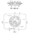
- a known audio-frequency electromechanical vibrator 1 shown therein comprises a magnetic circuit constituted by a magnetic yoke 2 of a inversed T-shape having a center pillar 2a and a bottom plate 2b, a ring-shaped permanent magnet 3 disposed on bottom plate 2b, and an annular top yoke plate 4 attached on permanent magnet 3.
- An annular small space or a magnetic gap 5 is formed between a top portion of center pillar 2a and an inner end of annular plate 4.
- a drive coil 6 is loosely fitted or disposed in the magnetic gap 5.
- the magnetic circuit structure is elastically supported by a case 7 through a spring plate 8, and drive coil 6 is supported by a case cover 9 through a coil bobbin 10.
- drive coil 6 Since drive coil 6 is disposed in a static magnetic field generated in the magnetic gap 5, drive coil 6 and the magnetic circuit structure (2-3-4) are relatively moved when an electric A.C. current is applied to drive coil 6. Thus, the vibrator 1 vibrates in response to an electric audio signal applied to drive coil.
- the known vibrator 1 Since drive coil 6 is loosely fitted in the magnetic small gap 5, it is a small coil of a thin wire, so that a large current cannot be applied to drive coil 6. Therefore, the known vibrator 1 has a problem that a strong and neat vibration cannot be generated, as described hereinabove.
- case cover 9 is made of a thin and good heat conductivity material. This means that cover plate 9 vibrates in response to a higher frequency component included in an audio-frequency signal applied to the vibrator to make noise, as described hereinabove. Therefore, a filter must be used before the audio-frequency signal is applied to the vibrator.
- the present invention resolves such problems and provides an improved audio-frequency electromechanical vibrator.
- a vibrator 11 according to an emboodiment of the present invention has an open-topped case 12 of a magnetic material and a cover case 13 closing the open top end of the case 12.
- a ring-shaped permanent magnet 14 axially magnetized is fixedly mounted onto an inner bottom surface of case 12.
- An annular coil 15 is disposed to face magnet 14 with a space therebetween.
- the annular coil 15 is contained in an annular coil housing 16 of a magnetic material.
- the coil 15 is secured to coil housing 16 by, for example, adhesive agent to form a coil unit.
- the coil housing 16 is fixed to a spring plate 17 which is fixedly secured to case 12, so that the coil unit is elastically supported by spring plate 17 in case 12.
- An electric cable 18 is led into case 12 through a hole 13a formed in case cover 13 and is electrically connected to coil 15.
- a gum bushing 19 is fitted in hole 13a to hold electric cable 18.
- Case 12 has an outer annular flange portion 12a to which a vibration plate 20 is joined.
- coil unit (15-16) faces an axial end of ring-shaped magnet 14 and is disposed in a large space in case 12, a large coil can be used in the vibrator which has a large number of windings and made of a thick wire. Therefore, the vibrator can generate strong and neat vibration with a reduced heat generation.
- the vibrator can be made flat and compact by the use of a flat coil unit and a flat magnet.
- cover plate 13 since cover plate 13 is not directly connected to coil 15 and magnet 14 which are relatively moved, it is not directly vibrated by coil 15 or magnet 14. Therefore, cover plate 13 does not generate noise even if it is made of a thin and good heat-conductivity plate. This means that a filter is not necessary for removing a higher frequency component from an audio-frequency signal applied to the vibrator.
- the vibrator is adapted to, for example, a chair.
- vibrator 11 is mounted in a chair back 21a of a chair 21 by securing vibration plate 20 to a cushion spring 22 in the chair back by, for example, strings or tapes 23.
- a person o the chair 21 feels vibration at his back when an audio signal is applied to the vibrator 11.
- a right channel (R) signal and a left channel signal (L) are applied to respective speakers 24R and 24L from an audio signal amplifier (not shown).
- the R and L signals are also inputted into a mixer circuit 25.
- the output signal from mixer 25 is applied to coil 15 of vibrator 11 through a filter 26 and a power amplifier.
- Filter 26 is for removing a frequency component lower than 99 Hz from the output of mixer 25, because such a lower frequency sound makes a person unpleasant.
- FIG. 6 and 7 another embodiment 11' shown therein is similar to the vibrator 11 in Figs. 2 and 3 but is different therefrom, mainly, in support of the coil unit.
- the similar parts are represented by the same reference numerals as Figs. 2 and 3, and a detailed description thereto is omitted for purpose of simplification of the description.
- a central portion of a bottom of a case 12' is raised upwardly so that the case 12' is formed to have a cross section of a W-like shape.
- the case has a central boss portion 12'a.
- Ring-shaped permanent magnet 14 and the coil unit (15-16) are disposed in an annular space around the central boss portion 12'a, Magnet 14 is fixedly mounted on the inner bottom of case 12', and coil init (15-16) faces magnet 14 with a space therebetween.
- Coil unit (15-16) is fixed to a spring plate 17'.
- Spring plate 17' is fixedly secured to boss portion 12'a by joining a central portion of spring plate 17' to the top end of boss portion 12'aby, for example, a rivet 28, so that boss portion 12'a,spring plate 17' and coil unit (15-16) are disposed coaxial. Thereby, coil unit 15-16 can vibrate uniformly without inclination.
- Terminal plates 29a and 29b are mounted in an annular wall of boss portion 12'a, and lead wires 15a and 15b are connected to terminals 30a and 30b of terminal plates 29a and 29b.
- Electric cable 18 is led out to the back side of the case 12' through gum bushing 19 and a central hole of rivet 28, and is connected to terminals 30a and 30b, as shown in Fig. 6.
- electric cable 18 can be adapted to vibrator 11' without removal of case cover 1.3 after the vibrator is completely assembled.
- a ring shaped felt 31 is overlaid onto magnet 14 to form a buffer between the magnet and the coil unit (15-16).
- a ring :.ember 32 of a soft and porous, such as sponge-like material is disposed around magnet 14 to serve as another buffer between magnet 14 and the coil unit (15-16).
- Case 12' is provided with a number of small holes 12'b along the ring member 32 so that holes 12'b are closed by the ring member. Air in the case 12' is exchanged through holes 12'b and the sponge-like ring member serves as a filter for removing dust.
- Vibratio- plate 20' is of a hard material, and may be backed with another plate 35 of a soft material.
- the permanent magnet is fixedly mounted to the case and the coil unit is elastically supported by the spring plate.
- the magnet and the coil unit may be mounted to the spring plate and the case, respectively.
Landscapes
- Physics & Mathematics (AREA)
- Electromagnetism (AREA)
- Engineering & Computer Science (AREA)
- Acoustics & Sound (AREA)
- Signal Processing (AREA)
- Health & Medical Sciences (AREA)
- Epidemiology (AREA)
- Pain & Pain Management (AREA)
- Physical Education & Sports Medicine (AREA)
- Rehabilitation Therapy (AREA)
- Life Sciences & Earth Sciences (AREA)
- Animal Behavior & Ethology (AREA)
- General Health & Medical Sciences (AREA)
- Public Health (AREA)
- Veterinary Medicine (AREA)
- Details Of Audible-Bandwidth Transducers (AREA)
- Apparatuses For Generation Of Mechanical Vibrations (AREA)
- Percussion Or Vibration Massage (AREA)
- Electrostatic, Electromagnetic, Magneto- Strictive, And Variable-Resistance Transducers (AREA)
Applications Claiming Priority (6)
| Application Number | Priority Date | Filing Date | Title |
|---|---|---|---|
| JP161395/83U | 1983-10-19 | ||
| JP16139583U JPS6071386U (ja) | 1983-10-19 | 1983-10-19 | 振動装置 |
| JP161394/83U | 1983-10-19 | ||
| JP16139483U JPS6071385U (ja) | 1983-10-19 | 1983-10-19 | 振動装置 |
| JP161396/83U | 1983-10-19 | ||
| JP16139683U JPS6068779U (ja) | 1983-10-19 | 1983-10-19 | 振動装置 |
Publications (3)
| Publication Number | Publication Date |
|---|---|
| EP0139302A2 true EP0139302A2 (de) | 1985-05-02 |
| EP0139302A3 EP0139302A3 (en) | 1987-12-09 |
| EP0139302B1 EP0139302B1 (de) | 1991-05-29 |
Family
ID=27321844
Family Applications (1)
| Application Number | Title | Priority Date | Filing Date |
|---|---|---|---|
| EP84112649A Expired EP0139302B1 (de) | 1983-10-19 | 1984-10-19 | Elektromechanischer Vibrator im Audio-Frequenz-Bereich |
Country Status (6)
| Country | Link |
|---|---|
| US (1) | US4635287A (de) |
| EP (1) | EP0139302B1 (de) |
| KR (1) | KR900001413B1 (de) |
| AU (1) | AU579838B2 (de) |
| CA (1) | CA1218939A (de) |
| DE (1) | DE3484641D1 (de) |
Cited By (1)
| Publication number | Priority date | Publication date | Assignee | Title |
|---|---|---|---|---|
| US4914750A (en) * | 1987-07-13 | 1990-04-03 | Avm Hess, Inc. | Sound transducer |
Families Citing this family (22)
| Publication number | Priority date | Publication date | Assignee | Title |
|---|---|---|---|---|
| US4354067A (en) * | 1978-05-17 | 1982-10-12 | Bodysonic Kabushiki Kaisha | Audio-band electromechanical vibration converter |
| DE3527501A1 (de) * | 1984-09-03 | 1986-03-13 | Sanden Corp., Isesaki, Gunma | Dynamische wandlereinrichtung |
| JPS6167400A (ja) * | 1984-09-11 | 1986-04-07 | Sanden Corp | 電気機械振動変換装置 |
| DE3541350A1 (de) * | 1985-11-22 | 1987-06-04 | Pius Voegel | Therapiegeraet fuer den menschlichen koerper |
| US4757548A (en) * | 1985-12-02 | 1988-07-12 | Fenner Jr Thomas C | Speaker system and dome-shaped enclosure therefor |
| DE3825454A1 (de) * | 1988-07-27 | 1990-02-01 | Gfpe Verlag & Seminar | Liege |
| US5606754A (en) | 1989-03-09 | 1997-03-04 | Ssi Medical Services, Inc. | Vibratory patient support system |
| US5103223A (en) * | 1990-01-26 | 1992-04-07 | Humphrey Jerry J | Street crossing signal |
| US5035235A (en) * | 1990-06-25 | 1991-07-30 | Chesky Kris S | Music vibration table and system |
| US5247925A (en) * | 1991-12-23 | 1993-09-28 | Kabushiki Kaisha Japan Health | Chair for office work with vibration structure |
| US5473700A (en) * | 1993-11-24 | 1995-12-05 | Fenner, Jr.; Thomas C. | High gain acoustic transducer |
| CA2258762C (en) * | 1996-06-21 | 2002-12-31 | Sanyo Electric Co., Ltd. | Notifying vibration generator and portable communications device wherein the generator is used |
| US6600399B1 (en) | 2002-02-05 | 2003-07-29 | Roland Pierre Trandafir | Transducer motor/generator assembly |
| US7981064B2 (en) | 2005-02-18 | 2011-07-19 | So Sound Solutions, Llc | System and method for integrating transducers into body support structures |
| US7418108B2 (en) * | 2004-02-19 | 2008-08-26 | So Sound Solutions, Llc | Transducer for tactile applications and apparatus incorporating transducers |
| US8077884B2 (en) * | 2004-02-19 | 2011-12-13 | So Sound Solutions, Llc | Actuation of floor systems using mechanical and electro-active polymer transducers |
| US7219690B2 (en) * | 2004-03-11 | 2007-05-22 | Watkins Manufacturing Corporation | Flow control valve |
| KR100645442B1 (ko) * | 2005-07-25 | 2006-11-14 | 삼성전자주식회사 | 칼라 하프톤 스크린 설계 방법 및 그 장치 |
| US20100056847A1 (en) * | 2007-04-18 | 2010-03-04 | Koninklijke Philips Electronics N.V. | Electro-mechanical massage device and wearable massage apparatus |
| US20100048980A1 (en) * | 2007-04-18 | 2010-02-25 | Koninklijke Philips Electronics N.V. | Electro-mechanical massage device and wearable massage apparatus |
| US20110166486A1 (en) * | 2009-05-01 | 2011-07-07 | Norio Kumanomido | Compact and light weight portable transducer massager |
| US20110044486A1 (en) * | 2009-08-24 | 2011-02-24 | Borkowski Gregory P | Personal back bass system |
Family Cites Families (13)
| Publication number | Priority date | Publication date | Assignee | Title |
|---|---|---|---|---|
| BE469578A (de) * | 1945-11-30 | |||
| US2957053A (en) * | 1956-02-21 | 1960-10-18 | Gen Phones Corp | Audio-electric translating device |
| US3185767A (en) * | 1960-10-10 | 1965-05-25 | Rca Corp | Loudspeakers |
| US3366749A (en) * | 1964-04-09 | 1968-01-30 | Allen Alan A | Audio transducer |
| GB1063914A (en) * | 1965-01-11 | 1967-04-05 | Plessey Co Ltd | Improvements in or relating to arrangements embodying flexible electric leads for electro-acoustic loudspeakers |
| US3801943A (en) * | 1971-06-16 | 1974-04-02 | J Bertagni | Electoacoustic transducers and electromagnetic assembly therefor |
| GB1530688A (en) * | 1975-04-08 | 1978-11-01 | Bodysonic Kk | Sound reproduction system |
| JPS553233A (en) * | 1978-06-22 | 1980-01-11 | Bodeisonitsuku Kk | Acoustic vibration device |
| US4506379A (en) * | 1980-04-21 | 1985-03-19 | Bodysonic Kabushiki Kaisha | Method and system for discriminating human voice signal |
| FR2488765A1 (fr) * | 1980-08-13 | 1982-02-19 | Telephonie Ind Commerciale | Transducteur electrodynamique |
| FR2503516B1 (fr) * | 1981-04-01 | 1986-02-07 | Klein Siegfried | Haut-parleur electrodynamique omnidirectionnel pour les frequences basses et medium du spectre sonore |
| NL8301460A (nl) * | 1983-04-26 | 1984-11-16 | Philips Nv | Elektroakoestische omzettereenheid met verlaagde resonantiefrekwentie. |
| JPS6167400A (ja) * | 1984-09-11 | 1986-04-07 | Sanden Corp | 電気機械振動変換装置 |
-
1984
- 1984-10-17 US US06/661,916 patent/US4635287A/en not_active Ceased
- 1984-10-18 AU AU34469/84A patent/AU579838B2/en not_active Ceased
- 1984-10-19 CA CA000465989A patent/CA1218939A/en not_active Expired
- 1984-10-19 EP EP84112649A patent/EP0139302B1/de not_active Expired
- 1984-10-19 KR KR1019840006514A patent/KR900001413B1/ko not_active Expired
- 1984-10-19 DE DE8484112649T patent/DE3484641D1/de not_active Expired - Lifetime
Cited By (1)
| Publication number | Priority date | Publication date | Assignee | Title |
|---|---|---|---|---|
| US4914750A (en) * | 1987-07-13 | 1990-04-03 | Avm Hess, Inc. | Sound transducer |
Also Published As
| Publication number | Publication date |
|---|---|
| CA1218939A (en) | 1987-03-10 |
| KR850002947A (ko) | 1985-05-28 |
| AU3446984A (en) | 1985-04-26 |
| US4635287A (en) | 1987-01-06 |
| EP0139302A3 (en) | 1987-12-09 |
| EP0139302B1 (de) | 1991-05-29 |
| AU579838B2 (en) | 1988-12-15 |
| KR900001413B1 (ko) | 1990-03-09 |
| DE3484641D1 (de) | 1991-07-04 |
Similar Documents
| Publication | Publication Date | Title |
|---|---|---|
| EP0139302B1 (de) | Elektromechanischer Vibrator im Audio-Frequenz-Bereich | |
| KR0148085B1 (ko) | 헤드폰 | |
| USRE32785E (en) | Audio-frequency electromechanical vibrator | |
| EP0891117A3 (de) | Lautsprecher und Tonwiedergabeanordnung mit einem solchen Lautsprecher | |
| US4680492A (en) | Audio-frequency electromechanical vibrator | |
| JP2002238089A (ja) | 電気−機械−音響変換器 | |
| US3178512A (en) | Electrical sound reproducing device | |
| US3679833A (en) | Loudspeaker system | |
| JP3045032B2 (ja) | ヘッドホン | |
| JP4601410B2 (ja) | スピーカ装置 | |
| CN114391261A (zh) | 扬声器单元及扬声器 | |
| KR20060058078A (ko) | 휴대단말기용 기능성스피커 | |
| KR200421900Y1 (ko) | 휴대단말기용 기능성스피커 | |
| KR960016675B1 (ko) | 청각장애자용 음향 청취 장치 | |
| JP3904797B2 (ja) | スピーカ装置 | |
| KR200333043Y1 (ko) | 진동 스피커 | |
| KR200253585Y1 (ko) | 음향기기를 이용한 진동장치 | |
| KR920002442B1 (ko) | 스피커 | |
| JP4035709B2 (ja) | スピーカおよびスピーカシステム | |
| JP2000197185A (ja) | バイザ―用スピ―カ | |
| JPH11207027A (ja) | ゲーム機 | |
| JPH0733517Y2 (ja) | 電気音響変換器 | |
| KR200264896Y1 (ko) | 평면형 스피커 | |
| JP2006093774A (ja) | ステレオ対応多機能型振動アクチュエータ | |
| JPH11206834A (ja) | マッサージ機 |
Legal Events
| Date | Code | Title | Description |
|---|---|---|---|
| PUAI | Public reference made under article 153(3) epc to a published international application that has entered the european phase |
Free format text: ORIGINAL CODE: 0009012 |
|
| 17P | Request for examination filed |
Effective date: 19841228 |
|
| AK | Designated contracting states |
Designated state(s): DE FR GB IT SE |
|
| PUAL | Search report despatched |
Free format text: ORIGINAL CODE: 0009013 |
|
| AK | Designated contracting states |
Kind code of ref document: A3 Designated state(s): DE FR GB IT SE |
|
| 17Q | First examination report despatched |
Effective date: 19890424 |
|
| GRAA | (expected) grant |
Free format text: ORIGINAL CODE: 0009210 |
|
| AK | Designated contracting states |
Kind code of ref document: B1 Designated state(s): DE FR GB IT SE |
|
| ITF | It: translation for a ep patent filed | ||
| ET | Fr: translation filed | ||
| REF | Corresponds to: |
Ref document number: 3484641 Country of ref document: DE Date of ref document: 19910704 |
|
| PLBE | No opposition filed within time limit |
Free format text: ORIGINAL CODE: 0009261 |
|
| STAA | Information on the status of an ep patent application or granted ep patent |
Free format text: STATUS: NO OPPOSITION FILED WITHIN TIME LIMIT |
|
| 26N | No opposition filed | ||
| PGFP | Annual fee paid to national office [announced via postgrant information from national office to epo] |
Ref country code: GB Payment date: 19931011 Year of fee payment: 10 Ref country code: FR Payment date: 19931011 Year of fee payment: 10 |
|
| PGFP | Annual fee paid to national office [announced via postgrant information from national office to epo] |
Ref country code: SE Payment date: 19931015 Year of fee payment: 10 |
|
| PGFP | Annual fee paid to national office [announced via postgrant information from national office to epo] |
Ref country code: DE Payment date: 19931021 Year of fee payment: 10 |
|
| PG25 | Lapsed in a contracting state [announced via postgrant information from national office to epo] |
Ref country code: GB Effective date: 19941019 |
|
| PG25 | Lapsed in a contracting state [announced via postgrant information from national office to epo] |
Ref country code: SE Effective date: 19941020 |
|
| EAL | Se: european patent in force in sweden |
Ref document number: 84112649.3 |
|
| GBPC | Gb: european patent ceased through non-payment of renewal fee |
Effective date: 19941019 |
|
| PG25 | Lapsed in a contracting state [announced via postgrant information from national office to epo] |
Ref country code: FR Effective date: 19950630 |
|
| PG25 | Lapsed in a contracting state [announced via postgrant information from national office to epo] |
Ref country code: DE Effective date: 19950701 |
|
| EUG | Se: european patent has lapsed |
Ref document number: 84112649.3 |
|
| REG | Reference to a national code |
Ref country code: FR Ref legal event code: ST |