EP0139367A1 - Vorrichtung zur Reinigung von Becherwerken - Google Patents
Vorrichtung zur Reinigung von Becherwerken Download PDFInfo
- Publication number
- EP0139367A1 EP0139367A1 EP84305394A EP84305394A EP0139367A1 EP 0139367 A1 EP0139367 A1 EP 0139367A1 EP 84305394 A EP84305394 A EP 84305394A EP 84305394 A EP84305394 A EP 84305394A EP 0139367 A1 EP0139367 A1 EP 0139367A1
- Authority
- EP
- European Patent Office
- Prior art keywords
- cleaning
- bucket elevator
- cleaning device
- folded
- cleaning element
- Prior art date
- Legal status (The legal status is an assumption and is not a legal conclusion. Google has not performed a legal analysis and makes no representation as to the accuracy of the status listed.)
- Withdrawn
Links
- 238000004140 cleaning Methods 0.000 title claims abstract description 111
- 230000009471 action Effects 0.000 claims description 16
- 238000005452 bending Methods 0.000 claims description 5
- 238000007790 scraping Methods 0.000 claims description 3
- 239000000428 dust Substances 0.000 abstract description 5
- 238000011109 contamination Methods 0.000 abstract description 2
- 235000013339 cereals Nutrition 0.000 description 22
- 230000000694 effects Effects 0.000 description 5
- 241000237858 Gastropoda Species 0.000 description 4
- 210000000078 claw Anatomy 0.000 description 4
- 230000002441 reversible effect Effects 0.000 description 4
- 238000004873 anchoring Methods 0.000 description 2
- 238000007599 discharging Methods 0.000 description 2
- 230000004048 modification Effects 0.000 description 2
- 238000012986 modification Methods 0.000 description 2
- 238000010408 sweeping Methods 0.000 description 2
- 238000010276 construction Methods 0.000 description 1
- 235000013312 flour Nutrition 0.000 description 1
- 230000006872 improvement Effects 0.000 description 1
- 239000000463 material Substances 0.000 description 1
- 230000009467 reduction Effects 0.000 description 1
Images


Classifications
-
- B—PERFORMING OPERATIONS; TRANSPORTING
- B07—SEPARATING SOLIDS FROM SOLIDS; SORTING
- B07B—SEPARATING SOLIDS FROM SOLIDS BY SIEVING, SCREENING, SIFTING OR BY USING GAS CURRENTS; SEPARATING BY OTHER DRY METHODS APPLICABLE TO BULK MATERIAL, e.g. LOOSE ARTICLES FIT TO BE HANDLED LIKE BULK MATERIAL
- B07B13/00—Grading or sorting solid materials by dry methods, not otherwise provided for; Sorting articles otherwise than by indirectly controlled devices
-
- B—PERFORMING OPERATIONS; TRANSPORTING
- B65—CONVEYING; PACKING; STORING; HANDLING THIN OR FILAMENTARY MATERIAL
- B65G—TRANSPORT OR STORAGE DEVICES, e.g. CONVEYORS FOR LOADING OR TIPPING, SHOP CONVEYOR SYSTEMS OR PNEUMATIC TUBE CONVEYORS
- B65G45/00—Lubricating, cleaning, or clearing devices
- B65G45/10—Cleaning devices
- B65G45/12—Cleaning devices comprising scrapers
- B65G45/14—Moving scrapers
Definitions
- the present invention relates to an improvement in a cleaning device for a bucket elevator for grains, grain flour and other materials.
- the typical bucket elevator has been known as having such construction that an upright casing is provided at its top portion with a shaft carrying a head wheel and at its bottom portion a shaft carrying a foot wheel; an endless belt mounting thereon a number of buckets at spaced inter- va 1 s is mounted over the head and foot wheels.
- the grains supplied to an inlet port disposed at the lower portion of the casing are scooped up and elevated up to the top portion of the casing by the buckets travelling within the casing, and the thus elevated grains are discharged through a grain discharging port by centrifugal action as the buckets pass over the head wheel.
- an object of the present invention is to overcome the above-described problems of the prior art.
- the present invention provides a cleaning device for a bucket elevator which includes a swing member carrying a cleaning element such as brushes or a resilient thin plate member, which swings with respect to the endless belt and is capable of being folded-in while the cleaning operation is not in progress and folded-out while the cleaning operation is in progress and, if necessary, a cleaning element contracting means which is capable of reducing the width of the cleaning element when it is in its folded-in position, whereby the cleaning element can travel within the casing without friction with or touching on the inner wall of the casing.
- a cleaning element contracting means which is capable of reducing the width of the cleaning element when it is in its folded-in position, whereby the cleaning element can travel within the casing without friction with or touching on the inner wall of the casing.
- the bucket elevator having the cleaning device of the invention it is possible to effect the cleaning operation only when optionally necessary in the course of a long operation thereby preventing the inside surface of the casing as well as the cleaning device itself from being damaged and also completely avoiding extraneous matter adhering onto the inner wall of the casing and grains remaining at the bottom of the casing.
- a bucket elevator embodying the present invention has an upright casing 1 at an upper portion of which is provided with a shaft 2 carrying a head wheel and at a lower portion of which is provided with a shaft 3 carrying a foot wheel.
- An endless bucket belt 5 carrying thereon a number of buckets 4... at spaced intervals runs around the head and foot wheels and thus provides, in combination with other parts, an elevator of a bucket belt type.
- the numeral 6 represents a head shaft takeup means of the screw type arranged for the purpose of compensating the variations in length of the bucket belt 5 due to temperature changes, atmospheric conditions, or wear.
- the numeral 7 represents a grain inlet port which is disposed at the lower portion of the casing 1.
- the numeral 9 represents a grain discharging port through which the grains elevated by the travelling buckets are discharged out of the casing.
- the numerals 10 and 20 represent the cleaning device of the present invention, which will be fully explained hereunder.
- a first embodiment of the cleaning device which comprises a cleaning element 8 which may be made of brushes or a resilient plate member such as a rubber plate; a swing member 105 in the form of divided swing frames 105a and 105b, which swings together with the cleaning element 8 from its folded-in position to the folded-out position and vice versa with respect to the endless bucket belt 5; and a control means 20 including a pair of racks 22A and 22B, which is provided on the wall of the casing 1 in such a way that the racks 22A and 22B can alternately protrude and retreat from the inner surface of the same casing.
- the swing frames 105a and 105b are swingably supported by a fixing member including a base plate 101 secured on the surface of the bucket belt 5 and having a rotatable bar 102 carried between the two side wall portions 101a and 101b thereof.
- a pair of nut members 103 and 104, to which the swing frames 105a and 105b are fixed respectively, are movable on the rotatable bar 102.
- the respective threaded portions on the bar 102 where the respective nuts 103 and 104 are mounted are oppositely oriented so that the rotation of the bar 102 in one direction causes the nut members 103 and 104 together with the respective swing frames 105a and 105b to move away from each other and in the other direction causes the same nuts to move closer to each other, whereby the width of the swing member 105 together with the cleaning element 8 is expanded when the swing member 105 is in its folded-out position and is contracted to reduce the width of the swing member 105 when it is in its folded-in position.
- the swing frames 105a and 105b carry respectively at their leg portions hook engaging plates 107 and 108 to be hooked for being folded-out and folded-in.
- hooking arms 109 and 110 On the intermediate non-threaded portion of the rotatable bar 102, there are provided hooking arms 109 and 110 in such a way that, as the bar 102 rotates, either of these hooking arms 109 and 110, as the case may be, will abut either of the above hook engaging plates 107 and 108 to fold-out or fold-in the swing frames 105a and 105b together with the cleaning element 8.
- a pinion 120 is fixed at one end portion of the bar 102.
- the wall of the casing 1 carries the control means 20 including the racks 22A, 22B for engagement with the pinion 120 for the folding-out and folding-in action of the swing member 105.
- Solenoids 24A and 24B are respectively connected to the racks 22A and 22B.
- the solenoid 24A for the folding-out action provided in the control means 20 is actuated to cause the associated rack 22A to protrude from the inner surface of the wall so that the pinion 120 fixed to the end of the bar 102 engages with the rack 22A thereby effecting the rotation of the pinion 120 and hence the rotation of the bar 102.
- the solenoid 24A for the folding-out action provided in the control means 20 is actuated to cause the associated rack 22A to protrude from the inner surface of the wall so that the pinion 120 fixed to the end of the bar 102 engages with the rack 22A thereby effecting the rotation of the pinion 120 and hence the rotation of the bar 102.
- the swing frames 105a and 105b assume a predetermined expanded position and the hooking arm 109 hooks and presses up the hook engaging plate 107 together with the hook engaging plate 108 so as to fold-out the swing frames 105a and 105b.
- the cleaning element 8 in the folded-out position and the buckets 4... travel within the casing 1 and, thus, any extraneous matter adhering to the inner wall or any grains remaining at the bottom are removed and discharged from the bucket elevator.
- the folding-in action of the cleaning element 8 is effected in such a manner that, when the solenoid 24B provided in the control means 20 is actuated to cause the associated rack 22B to protrude from the inner surface of the wa 11, the pinion 120 engages with the rack 22B thereby effecting the reverse rotation of the pinion 120 and hence the reverse rotation of the bar 102.
- This reverse rotation causes the swing frames 105a and 105b to assume a contracted position and the hooking arm 110 to hook and press down the hook engaging plate 108 together with the hook engaging plate 107 so as to fold-in the swing frames 105a and 105b.
- both the racks 22A and 22B in the control means 20 are in a position in which these racks are retreated from the inner wall surface of the casing.
- Fig. 5 the folded-out position of the cleaning element 8 with respect to the endless bucket belt 5 is shown by the full line and the folded-in position with respect to the same belt by the two-dots-and-dash line.
- Figs. 6 and 7 show a second embodiment of the present invention in which the cleaning device is so arranged that an anchoring means 201 is provided near one side-edge portion of a swing plate 209 and a spring 204 is provided between the anchoring means 201 and a stationary arm 203 extending from the fixing meriber, that is, a base plate 202, and there are provided lexers such as folding-out lever 206a and folding-in lever 206': at one end of the bar 206.
- the tension of the spring 204 causes the swing member, that is, the swing plate 209 to flir -out and flip-in when either of the above folding levers 206a and 206b is actuated.
- the cleaning plate 8 may easily be folded-out and folded-in by the manual actuation of the folding-out and -in levers 206a, 206b, but it is to be noted that, as explained later, the control means 20 may be provided on the wal 1 of the casing so as to effect the folding-out and folding-in action of the cleaning plate 8 while the bucket belt is travelling within the casing. Further, the folded-out angular position of the cleaning plate 8 during the cleaning operation is maintained by the tension of the spring 204 and the abutment of the upper surface of the swing plate 209 to the underside surface of a stopper plate 208 which horizontally extends from the base plate 202.
- a fixing member that is, a bent base plate 302 consisting of a first base plate portion 302a and a second base plate portion 302b for mounting on its underside surface a first cleaning element 8a.
- the second base plate portion 302b is provided at its side edges with a pair of arms 305 and 306 standing opposite to each other thereat.
- a swing plate 307 mounting on its underside surface a second cleaning element 8b and having a pair of arms 308 and 309 at its side edges is swingably carried by the bent base plate 302 in such a manner that their arms 308 and 309 are pivoted at respective pivots 310 and 311 of the arms 305 and 306 standing from the side edges of the second base plate portion 302b.
- the first base plate portion 302a and the swing plate 307 have a spring member 312 therebetween so that the swing plate 307 can swing back and forth from its horizontal position to a vertical position with respect to the second base plate portion 302b.
- a folding-out handle 314 is fixed to the arm 3:8 for effecting the folding-out action of the swing plate 3f 7 and a folding-in handle 315 is fixed to the arm 309 for effecting the folding-in action of the same plate 307. Due to the appropriate tension of the spring 312, the flip-out and flip-in action of the swing plate 307 can surely and easily be effected. Also, when the swing plate 307 moves upwardly to assume its vertical position, that is, the folded-in position, both the side edge portions of the first and second cleaning elements 8a and 8b are pressed away by the respective end portions of the arms 308, 309 and 305, 306, and, thus, are prevented from being in contact with the inner wall of the casing. Therefore, any damage or wear which may otherwise be caused by the frictional contact of the cleaning elements 8a and 8b can be effectively avoided.
- the cleaning element 8(8b) can easily be folded-out and folded-in by the manual actuation of the folding-out and folding-in handles 314 and 315, but it is to be noted that, as explained later, the control means 20 may be provided on the wa 11 of the casing so as to effect the fold-out and fold-in action of the above cleaning element 8(8b) while the bucket belt is travelling within the casing.
- a fixing member 403 is secured on the endless bucket belt 5 by means of bolts and nuts. Between the two side wall portions 404 and 405 of the fixing member 403, there extends a rotatable bar 406 on which is provided a stop claw hook 408. The stop claw hook 408 is always forced clockwise by a spring 409. A folding-in handle 407 is fixed to one end portion of the rotatable bar 406.
- the lower parts of the above two wal portions 404 and 405 carry respectively shafts 410 and 411 on which a swing body 412 is mounted.
- a spring 413 is provided at the supporting shaft 410 so as to force always the swing body 412 clockwise and a folding-out handle 416 is fixed to the outer end portion of the supporting shaft 411.
- a snail cam plate 420 having an engaging groove 420a thereon is mounted on the supporting shaft 411.
- a cleaning element 8 of the cleaning device of this fourth embodiment comprises a grain scooping plate 401 for scraping and scooping up the grains remaining at the bottom of the casing 1 and a cleaning plate 402 made of such a resilient plate member as a rubber plate for sweeping out the dust or extraneous matter adhering onto the inner wall of the casing and remaining at the bottom of the casing.
- a connecting body 418, at the front edge of which is secured the grain scooping plate 401, and the cleaning plate 402 are both screw-fixed onto the underside surface of the swing body 412.
- the cleaning plate 402 has at its front edge portion a plurality of ribs 419 for removing or sweeping off the bran or dust firmly attached on the inside wall surface of the casing.
- the folding-out handle 416 is actuated to rotate the snail cam plate 420 to an appropriate extent, that is, until 1 the stop claw hook 408 on the rotatable bar 406 6 engages with the engaging groove 420a of the snail cam plate 420, so that the swing body 412 is folded-out together with the grain scooping plate 401 and the cleaning plate 402.
- the grain scooping plate 401 operates to scoop up any grains A having not been taken up by the buckets 4... and remaining at the bottom of the casing 1 and the cleaning plate 402 operates to sweep out any dust or extraneous matter B remaining there.
- the folding-in handle 407 is slightly moved in a counterclockwise direction so as to release the engagement of the stop claw hook 408 with the engaging groove 420a of the snail cam plate 420. Then, the swing body 412 is forced to move angularly clockwise due to the spring force of the spring 413 so that the grain scooping plate 401 and the cleaning plate 402 assume the folded-in position as shown in Fig. 11.
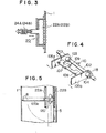
- the cleaning device shown in Fig. 12 is a modification of that shown in Fig. 9, which is further provided with a bending guide plate 425 provided underneath the fixing member 403.
- This bending guide plate 425 causes the side edges 402a and 402b of the cleaning plate 402 to be bent when this plate 402 is in the folded-in position.
- the side edges 402a and 402b of the cleaning plate 402 are respectively pressed and bent by the side wall portions 425a and 425b of the bending guide plate 425 in the manner as shown in Fig. 13. Accordingly, the span between the two side edges of the cleaning plate 402 is reduced so as to be able to avoid any damage or wear which would otherwise occur due to friction between the cleaning plate 402 and the inside wall surface of the casing 1. This will also facilitate smooth travelling of the endless belt 5 because of the reduction of load and also avoid wearing of the cleaning plate 402 and other parts associated thereto.
- Each of the cleaning elements 8 explained so far with respect to the second to fourth embodiments is such that it is possible for the cleaning element 8 to be easily folded-out and folded-in by the manual operation of the folding-out and folding-in levers or handles after the movement of the bucket belt is temporary stopped.
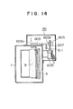
- Fig. 14 shows an example of the control means 20 installed on the wall of the casing 1, which can be employed in any of the second to fourth embodiments explained above.
- the cleaning element 8 is caused to be folded-out or folded-in as a hook portion 603a of a lever arm 603 pivotally provided on the casing 1 moves in or out and thus engages with the folding-out or folding-in lever 206a, 206b in the second embodiment, the folding-out or folding-in handle 314, 315 in the third embodiment, or the folding-out or folding-in handle 416, 407 in the fourth embodiment, as the case may be.
- An end portion 603b of the lever arm 603 is connected to a movable nut 605 engaging with a threaded shaft 607 connected to a shaft of a reversible electric motor 609.
- the numeral 611 represents a spring.
- the control means 20 may perform its function, as required, by way of remote control means.
- control means 20 shown in Fig. 14 is intended only to illustrate an example of arrangements, especially as to how the hook portion 603a of the lever 603 in the control means 20 engages with the levers or handles in the casing 1.
- the arrangements must suit the given types of levers or handles extending from the swing member and it will be a matter of design as to how the control means 20, especially the hook portion 603a, should be designed.
- the same arrangements as given in Fig. 14, at least those for th hook portion may be provided at the symmetrically opposite side of the casing so that the hook portion on one side engages with the folding-out handle and the other hook portion on the other side engages with the folding-in handle.
- the present invention made it possible to perform the cleaning operation only when optionally necessary, thereby preventing the inside surface of the casing as well as the cleaning device, especially the cleaning element, from being damaged or worn and also facilitating smooth travel of the bucket belt.
Landscapes
- Engineering & Computer Science (AREA)
- Mechanical Engineering (AREA)
- Chain Conveyers (AREA)
Applications Claiming Priority (4)
| Application Number | Priority Date | Filing Date | Title |
|---|---|---|---|
| JP19128883A JPS6082511A (ja) | 1983-10-12 | 1983-10-12 | 揚穀機の清掃装置 |
| JP191288/83 | 1983-10-12 | ||
| JP28299/84 | 1984-02-16 | ||
| JP2829984A JPS60171912A (ja) | 1984-02-16 | 1984-02-16 | 揚穀機の清掃体装置 |
Publications (1)
| Publication Number | Publication Date |
|---|---|
| EP0139367A1 true EP0139367A1 (de) | 1985-05-02 |
Family
ID=26366370
Family Applications (1)
| Application Number | Title | Priority Date | Filing Date |
|---|---|---|---|
| EP84305394A Withdrawn EP0139367A1 (de) | 1983-10-12 | 1984-08-08 | Vorrichtung zur Reinigung von Becherwerken |
Country Status (3)
| Country | Link |
|---|---|
| EP (1) | EP0139367A1 (de) |
| KR (1) | KR850003690A (de) |
| AU (1) | AU3162584A (de) |
Families Citing this family (1)
| Publication number | Priority date | Publication date | Assignee | Title |
|---|---|---|---|---|
| CN119160611B (zh) * | 2024-11-22 | 2025-06-06 | 苏州极味邦食品有限公司 | 一种具有清洁装置的带式输送装置 |
Citations (3)
| Publication number | Priority date | Publication date | Assignee | Title |
|---|---|---|---|---|
| AT62830B (de) * | 1912-05-28 | 1913-12-27 | Theodor Dahnert | Elevatorreiniger. |
| DE382667C (de) * | 1923-10-05 | Eugen Takacs | An einem Becherelevator sitzende Buersten zum Reinigen der Elevatorschaechte | |
| US1942590A (en) * | 1931-10-29 | 1934-01-09 | Delmar M Binger | Elevator cleaning device |
-
1984
- 1984-08-06 AU AU31625/84A patent/AU3162584A/en not_active Abandoned
- 1984-08-08 EP EP84305394A patent/EP0139367A1/de not_active Withdrawn
- 1984-10-12 KR KR1019840006317A patent/KR850003690A/ko not_active Withdrawn
Patent Citations (3)
| Publication number | Priority date | Publication date | Assignee | Title |
|---|---|---|---|---|
| DE382667C (de) * | 1923-10-05 | Eugen Takacs | An einem Becherelevator sitzende Buersten zum Reinigen der Elevatorschaechte | |
| AT62830B (de) * | 1912-05-28 | 1913-12-27 | Theodor Dahnert | Elevatorreiniger. |
| US1942590A (en) * | 1931-10-29 | 1934-01-09 | Delmar M Binger | Elevator cleaning device |
Also Published As
| Publication number | Publication date |
|---|---|
| KR850003690A (ko) | 1985-06-26 |
| AU3162584A (en) | 1985-04-18 |
Similar Documents
| Publication | Publication Date | Title |
|---|---|---|
| CA1056562A (en) | Disconnect and storage means for a windshield wiper arm assembly | |
| JPH04118411A (ja) | 液体流動流れから固体を除去する装置 | |
| USRE33154E (en) | Vehicle restraint | |
| EP0139367A1 (de) | Vorrichtung zur Reinigung von Becherwerken | |
| US5121970A (en) | Wheel barrow dump apparatus | |
| CN221439472U (zh) | 一种输送带自动清洗装置 | |
| US4533037A (en) | Telescoping conveyor belt cleaner | |
| US3019468A (en) | Wiper blade parking device | |
| KR100346938B1 (ko) | 컨베이어 벨트 크리너의 스크랩퍼 | |
| CN217577028U (zh) | 一种皮带输送机清扫装置 | |
| CN214929608U (zh) | 轮体自动清理装置 | |
| US1658312A (en) | Windshield cleaner | |
| CN109592251B (zh) | 一种便于倾倒的小区垃圾桶 | |
| US4621389A (en) | Windscreen wiper device | |
| JP2001058713A (ja) | ベルトコンベア | |
| JPH05263410A (ja) | 自動除塵機 | |
| JPS6035620Y2 (ja) | 除塵機 | |
| CN222862159U (zh) | 一种道路积雪铲除机构及除雪设备 | |
| JPS625062Y2 (de) | ||
| CN223254396U (zh) | 一种港口运货用运输带 | |
| JPH07158012A (ja) | 舗装車両における回転式スクレーパ装置 | |
| JPS5925045B2 (ja) | 除塵装置 | |
| JPH05338983A (ja) | 乗客コンベア清掃装置 | |
| JPS6038731Y2 (ja) | 除塵機 | |
| CN217285614U (zh) | 一种铝合金门窗安装时的清理装置 |
Legal Events
| Date | Code | Title | Description |
|---|---|---|---|
| PUAI | Public reference made under article 153(3) epc to a published international application that has entered the european phase |
Free format text: ORIGINAL CODE: 0009012 |
|
| AK | Designated contracting states |
Designated state(s): CH DE GB IT LI |
|
| STAA | Information on the status of an ep patent application or granted ep patent |
Free format text: STATUS: THE APPLICATION IS DEEMED TO BE WITHDRAWN |
|
| 18D | Application deemed to be withdrawn |
Effective date: 19860107 |
|
| RIN1 | Information on inventor provided before grant (corrected) |
Inventor name: SATAKE, TOSHIHIKO |