EP0139376A1 - System und Gerät zur kontinuierlichen Fraktionierung von Blut - Google Patents
System und Gerät zur kontinuierlichen Fraktionierung von Blut Download PDFInfo
- Publication number
- EP0139376A1 EP0139376A1 EP84305498A EP84305498A EP0139376A1 EP 0139376 A1 EP0139376 A1 EP 0139376A1 EP 84305498 A EP84305498 A EP 84305498A EP 84305498 A EP84305498 A EP 84305498A EP 0139376 A1 EP0139376 A1 EP 0139376A1
- Authority
- EP
- European Patent Office
- Prior art keywords
- blood
- outlet
- fraction
- blood flow
- inlet
- Prior art date
- Legal status (The legal status is an assumption and is not a legal conclusion. Google has not performed a legal analysis and makes no representation as to the accuracy of the status listed.)
- Granted
Links
- 210000004369 blood Anatomy 0.000 title claims abstract description 272
- 239000008280 blood Substances 0.000 title claims abstract description 272
- 238000011065 in-situ storage Methods 0.000 title claims abstract description 10
- 230000017531 blood circulation Effects 0.000 claims abstract description 89
- 238000012546 transfer Methods 0.000 claims abstract description 53
- 239000012528 membrane Substances 0.000 claims abstract description 49
- 238000000034 method Methods 0.000 claims abstract description 25
- 238000009826 distribution Methods 0.000 claims abstract description 23
- 239000003146 anticoagulant agent Substances 0.000 claims description 14
- 229940127219 anticoagulant drug Drugs 0.000 claims description 14
- FAPWRFPIFSIZLT-UHFFFAOYSA-M Sodium chloride Chemical compound [Na+].[Cl-] FAPWRFPIFSIZLT-UHFFFAOYSA-M 0.000 claims description 8
- 239000012530 fluid Substances 0.000 claims description 8
- 238000004519 manufacturing process Methods 0.000 claims description 7
- 239000011148 porous material Substances 0.000 claims description 7
- 239000011780 sodium chloride Substances 0.000 claims description 6
- 238000004891 communication Methods 0.000 claims description 5
- 238000005086 pumping Methods 0.000 claims description 4
- 230000014759 maintenance of location Effects 0.000 claims description 2
- 238000009827 uniform distribution Methods 0.000 abstract 1
- 210000002381 plasma Anatomy 0.000 description 83
- 238000003306 harvesting Methods 0.000 description 11
- 210000002105 tongue Anatomy 0.000 description 10
- 238000013461 design Methods 0.000 description 7
- 230000008901 benefit Effects 0.000 description 4
- 238000010276 construction Methods 0.000 description 4
- 230000003247 decreasing effect Effects 0.000 description 4
- 238000005534 hematocrit Methods 0.000 description 4
- 230000009467 reduction Effects 0.000 description 4
- 210000003743 erythrocyte Anatomy 0.000 description 3
- 239000000306 component Substances 0.000 description 2
- 238000002474 experimental method Methods 0.000 description 2
- 239000000706 filtrate Substances 0.000 description 2
- 238000001914 filtration Methods 0.000 description 2
- 238000012986 modification Methods 0.000 description 2
- 230000004048 modification Effects 0.000 description 2
- 238000005457 optimization Methods 0.000 description 2
- 230000008569 process Effects 0.000 description 2
- GXCDLJXPZVCHBX-UHFFFAOYSA-N 3-methylpent-1-yn-3-yl carbamate Chemical compound CCC(C)(C#C)OC(N)=O GXCDLJXPZVCHBX-UHFFFAOYSA-N 0.000 description 1
- 206010013082 Discomfort Diseases 0.000 description 1
- 238000012404 In vitro experiment Methods 0.000 description 1
- 230000001133 acceleration Effects 0.000 description 1
- 239000000853 adhesive Substances 0.000 description 1
- 230000001070 adhesive effect Effects 0.000 description 1
- 210000001367 artery Anatomy 0.000 description 1
- 238000010923 batch production Methods 0.000 description 1
- 230000009286 beneficial effect Effects 0.000 description 1
- 239000012503 blood component Substances 0.000 description 1
- 210000001772 blood platelet Anatomy 0.000 description 1
- 230000015556 catabolic process Effects 0.000 description 1
- 210000004027 cell Anatomy 0.000 description 1
- 230000000295 complement effect Effects 0.000 description 1
- 238000009833 condensation Methods 0.000 description 1
- 230000005494 condensation Effects 0.000 description 1
- 230000007423 decrease Effects 0.000 description 1
- 238000006731 degradation reaction Methods 0.000 description 1
- 230000001934 delay Effects 0.000 description 1
- 238000001514 detection method Methods 0.000 description 1
- 201000010099 disease Diseases 0.000 description 1
- 208000037265 diseases, disorders, signs and symptoms Diseases 0.000 description 1
- 238000005194 fractionation Methods 0.000 description 1
- 238000013023 gasketing Methods 0.000 description 1
- 230000006872 improvement Effects 0.000 description 1
- 208000015181 infectious disease Diseases 0.000 description 1
- 238000007689 inspection Methods 0.000 description 1
- 210000000265 leukocyte Anatomy 0.000 description 1
- 239000007788 liquid Substances 0.000 description 1
- 230000007246 mechanism Effects 0.000 description 1
- 230000002093 peripheral effect Effects 0.000 description 1
- 230000002572 peristaltic effect Effects 0.000 description 1
- 238000012545 processing Methods 0.000 description 1
- 230000007425 progressive decline Effects 0.000 description 1
- 230000002035 prolonged effect Effects 0.000 description 1
- 102000004169 proteins and genes Human genes 0.000 description 1
- 108090000623 proteins and genes Proteins 0.000 description 1
- 238000011084 recovery Methods 0.000 description 1
- 230000003252 repetitive effect Effects 0.000 description 1
- 239000007787 solid Substances 0.000 description 1
- 210000003462 vein Anatomy 0.000 description 1
- 238000003466 welding Methods 0.000 description 1
Images




Classifications
-
- B—PERFORMING OPERATIONS; TRANSPORTING
- B01—PHYSICAL OR CHEMICAL PROCESSES OR APPARATUS IN GENERAL
- B01D—SEPARATION
- B01D63/00—Apparatus in general for separation processes using semi-permeable membranes
- B01D63/08—Flat membrane modules
- B01D63/082—Flat membrane modules comprising a stack of flat membranes
-
- A—HUMAN NECESSITIES
- A61—MEDICAL OR VETERINARY SCIENCE; HYGIENE
- A61M—DEVICES FOR INTRODUCING MEDIA INTO, OR ONTO, THE BODY; DEVICES FOR TRANSDUCING BODY MEDIA OR FOR TAKING MEDIA FROM THE BODY; DEVICES FOR PRODUCING OR ENDING SLEEP OR STUPOR
- A61M1/00—Suction or pumping devices for medical purposes; Devices for carrying-off, for treatment of, or for carrying-over, body-liquids; Drainage systems
- A61M1/34—Filtering material out of the blood by passing it through a membrane, i.e. hemofiltration or diafiltration
- A61M1/3496—Plasmapheresis; Leucopheresis; Lymphopheresis
Definitions
- Plasma has been found to be efficacious in the treatment of various disease states and is generally useful since it may be stored for long periods in comparison to whole blood which has a rather short shelf life.
- plasma is harvested by transferring blood from a donor into a blood bag and thereafter centrifuging the blood to separate the plasma from the formed elements of the blood. Then the plasma is separated from the formed elements of the blood, the formed elements are thereafter reconstituted with a saline solution and reintroduced to the donor. Because of a variety of reasons, generally each donor must undergo two such operations for each plasma donation.
- the traditional manner of harvesting plasma involves several risks and discomforts to the donor.
- a principal risk is the chance that the reconstituted blood returned to the donor will not be the donor's, a situation which has in the past resulted in fatalities.
- Other attendant risks are those of infection and the like.
- the discomfort involves, among other things, the inordinate length of time required to permit two samples of blood to be taken with the required centrifuging of each sample, the large volume of blood removed for processing, the reconstituting of the formed elements into a saline solution and reintroducing same to the donor. It is clear that a simpler, safer, speedier system for harvesting plasma is needed and has been needed for a considerable length of time.
- This invention relates to a system, apparatus and method for continuously fractionating blood in situ.
- the fractionating device per se, is small and relatively inexpensive in contradistinction to the available prior art devices which are complicated and costly.
- the inventive system, apparatus and method permits blood to be taken from a donor and returned to the donor in a closed loop, thereby obviating any chance of returning incorrect blood, reducing the time necessary for plasma harvesting and reducing the cost of the equipment and labor necessary to obtain blood plasma.
- An important object of the present invention is to provide a system, apparatus and method for continuously fractionating blood in situ.
- the present invention provides a device for continuously producing a blood fraction, comprising a stack of at least two plates having at least one surface with a blood flow channel therein facing a surface with a collection channel therein separated by a semipermeable membrane selectively permeable to the blood fraction, an inlet for conducting blood to each blood flow channel and an outlet for conducting blood therefrom to establish a longitudinally extending blood flow path, each blood flow channel having a distribution portion for uniformly distributing blood transversely of the blood flow path and a transfer portion extending longitudinally thereof, each collection channel being substantially in registry with the transfer portion of the facing blood flow channel for receiving the blood fraction passing through the membrane, and a fraction outlet for conducting the blood fraction from each collection channel, whereby the blood fraction continuously transfers from blood passing through the transfer portion of each blood flow channel through the membrane to the adjacent collection channel to the fraction outlet.
- the present invention also provides a method of continuously fractionating blood in situ, comprising establishing a olosed loop between the blood donor and a device having a blood inlet and outlet and a blood fraction outlet, pumping blood from the donor to the blood inlet and through the device and from the blood outlet to the donor while continuously producing a blood fraction, and collecting the blood fraction from the blood fraction outlet.
- the present invention also provides a system for continuously producing a blood fraction in situ comprising a closed blood flow loop between a blood fraction donor and a fractionating device, a pump for pumping blood from the donor to the fractionating device and therefrom to the donor, the fractionating device comprising a stack of at least two plates having at least one surface with a blood flow channel therein facing a surface with a collection channel therein separated by a semipermeable membrane selectively permeable to the blood fraction, an inlet to the device connected to the closed loop for conducting blood to each blood flow channel and an outlet from the device connected to the closed loop for establishing a longitudinally extending blood flow path through the device, each blood flow channel having a distribution portion for uniformly distributing blood transversely of the blood flow path and a transfer portion extending longitudinally thereof, each collection channel being substantially in registry with the transfer portion of the facing blood flow channel for receiving the blood fraction passing through the membrane, a fraction outlet for conducting the blood fraction from each collection channel, and a receptacle for storing the blood fraction, where
- a blood fractionating system 20 which includes a blood fractionator 25 connected in a closed loop to a donor 30.
- the blood fractionator 25 has an inlet 26 and an outlet 36, the inlet 26 being connected to the donor 30 by a blood tube 27 connected to a catheter, needle or double lumen needle 28 inserted into an appropriate vein or artery of the donor 30.
- a peristaltic pump 31 having a roller 32 in contact with the blood tube 27 is positioned between the donor 30 and the inlet 26 of the blood fractionator 25 to pump blood from the donor through the tube 27 into the fractionator in the direction of the arrow 33.
- blood fractionator 25 of the present invention along with the system 20 disclosed herein may be useful to produce a variety of blood fractions
- plasma is one of the most important blood fractions needed in the medical community, and therefore, the blood fractionator 25 as well as the system 20 and method of collecting a blood fraction will hereinafter be described with respect to blood plasma only, it being understood that other blood fractions may be collected with minor modifications to the device 25 and system 20, as will be apparent to those skilled in the art.
- the blood fractionator 25 is made up of a stack 45 of plates, there being provided two external plasma plates 50 two internal blood plates 55 and an interior or internal plasma plate 60, an appropriate inlet manifold 65 and outlet manifold 70 with each of the plasma plates and blood plates being separated by an appropriate membrane 75.
- the blood fractionator 25 is comprised of a stack 45 of five separate plates and four membranes 75 interleaved between the plates such that each plasma plate 50, 60 faces a blood plate 55 and is separated therefrom by an appropriate membrane 75.
- the stack 45 could as easily be comprised of a stack of plates in which the external plates are blood plates having two double sided plasma plates separated by an internal double sided blood plate. The number of plates also could be increased.
- each external plasma plate 50 is an oval member 80 with an outer flat surface 81 opposed by an inner flat surface 82.
- the plate 50 is generally oval in shape and has a large inlet end 83 and a small outlet end 84.
- Each of the end plasma plates 50 has on the inside flat surface 82 thereof a plasma collection channel 90 which has a trapezoidal portion 91 defined by side edges 92 and end edges 93.
- Toward the small outlet end 84 of the end plasma plate 50 is a transversely extending slot 94 in fluid communicaiton with a plurality of longitudinally extending shallow collection grooves 95 separated by ridges 96.
- the slot 94 is substantially deeper than the shallow collection grooves 95 and the portion of the grooves 95 adjacent the slot 94 are deeper than the remainder of the grooves 95 but shallower than the slot.
- a plasma outlet 98 in the form of an aperture extending from the end surface 86a extends through the oval member 80 and is in fluid communication with the slot 94.
- an oval tongue 99 surrounds the plasma collection channel 90, for a purpose hereinafter explained.
- a blood plate 55 which is provided with the same configuration on both sides thereof, whereby only one side will be described for the sake of brevity.
- Each of the blood plates 55 is identical in configuration and has in the opposed flat surfaces 102 thereof a blood flow channel 100, the plate 55 being generally oval in shape and identical in size to the external plasma plates 50 previously described. For that matter, all of the plates 50, 55 and 60 have the same general dimensions in plan view.
- the blood plate 55 has an edge surface 101 and opposed flat side surfaces 102, it being the surfaces 102 in which the blood flow channels 100 are positioned.
- the blood plate 55 has a large inlet end 103 and a small outlet end 104, with recesses 105 being provided in the side edges as previously discussed with respect to the end plasma plates 50.
- there is a large notch 106 in the small outlet end 103 the notch having an end surface 106a and there is a small notch 107 at the large inlet end 103, the small notch 107 being provided with an end surface 107a.
- a groove 109 extends around the periphery of both flat side surfaces 102 and each is complementary in shape to the tongue 99 in the adjacent end plasma plate 50 and are shaped and dimensioned to receive therein the associated tongue 99 as well as the thickness of the membrane 75, as will be explained. Although shown with grooves on blood plate 55 and tongues on plates 50, the tongues and grooves can be interchanged.
- Each of the blood flow channels 100 has a distribution portion 110 and a collection portion 110a in the form of a multiple bifurcated manifolds, these distribution and collection portions are identical in shape but not in dimension, as will be explained, but for the case of brevity again, like numerals have been applied to like portions of the manifolds 110, 110a. Both the distribution portion 110 and the collection portion 110a, that is the bifurcated manifolds are in fluid communication with a transfer portion 160, all for a purpose hereinafter explained.
- an inlet aperture 112 extending through the end surface 107a of the notch 107 and extending longitudinally of the blood plate 55.
- the inlet 112 has a counterbore portion 113 at one end thereof and communicates with an aperture 114 which extends through the plate 55, as best seen in Figs. 6 and 11, so as to provide communication between the inlet manifold 65 and the blood flow channel 100 on both sides of the plate 55.
- the inside facing surface 114a of the aperture 114 is rounded at the juncture with the bifurcated manifold 110 to prevent contact of the blood flowing therethrough with a sharp edge for a purpose, as will hereinafter be set forth.
- Each of the channels 116 curves as at 118 into a secondary channel 119 which is again bifurcated into channels 121, both the arcuate portions 122 and 123 being formed to prevent stagnation and increase smooth flow of blood through the manifold 110.
- From the channels 121 the blood into the tertiary channel 129 where it is again bifurcated into channels 131 and channels 131 are again provided with arcuate surfaces 132 and 133 for the same purposes as previously described.
- the blood flows from channels 131 into the fourth tier of channels 149 where they are again bifurcated into channels 141, the channels 141 being provided with smooth arcuate surfaces 142 and 143 to prevent stagnation of blood as it flows through the distribution portion of the blood flow channel 100.
- a fifth tier channel 149 receives the blood from the channels 141 and is bifurcated as at 151 into two additional streams, thereby making the five bifurcations previously described with each of the channels 151 having rounded or arcuate smooth surfaces 152 and 153 to prevent any stagnation of blood and to enhance the flow characteristics-thereof.
- Each of the bifurcated channels 151 has an entrance 155 to the transfer portion 160 of the blood flow channel 100. As before indicated there are 32 entrances 155 to the transfer portion 160.
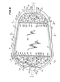
- the transfer portion 160 is generally trapezoidal in plan view and is defined by side edges 161 and end edges 162 with a generally flat uniformly deep surface 163 which is shallow and as hereinbefore set forth of the same depth as the entrances 155 from both the collection and distribution portions of manifolds 110, 110a. Because the transfer portion 160 of the blood flow channel 100 is trapezoidal in shape, that is it tapers from the inlet end 103 to the outlet end 104 of the plate 55, the transverse dimension of the collection manifold 110a is less than the transverse dimension of the distribution manifold 110. However, the configuration of the collection manifold 110a is precisely the same as the configuration of the distribution manifold 110; therefore, like numerals have been placed on like portions to prevent repetitive description.
- the entrances 155 of the collection manifold 110a at the end of the transfer portion 160 are identical in configuration and number but smaller in overall transverse dimension than the entrances 155 from the manifold 110.
- the same five bifurcations are in the manifold 110a as in the manifold 110 and the vertically extending aperture 114 with the same arcuate surface 114a connects the outlet 112a to the collection manifold 110a, the outlet 112a being provided in the end edge 106a of the notch 106 and having a counterbore portion 113a of the same size and dimension as the counterbore 113 at the inlet end 103.
- the collection manifold 110a has a varying depth in the same manner as the distribution manifold 110, that is the depth of the entrances 155 is the same as the depth of the transfer portion 160 and the depth of the manifold increases uniformly from the entrances 155 toward the aperture 114.
- the increase in depth is preferably uniform so that the depth of the manifold 110a would be exactly the same along a plane transverse to the longitudinally established blood flow path of the blood plate 55.
- the blood plate 55 has provided blood flow channels 100 on both sides thereof and each blood flow channel 100 is identical and has a distribution portion in the form of a multiple bifurcated manifold 110, a transfer portion 160 and a collection portion in the form of a multiple bifurcated manifold 110a.
- the blood flow is established longitudinally of the plate and flows from the inlet 112 through the end surface 107a of the notch 107 and exits through the outlet 112a through the end surface 106a of the notch 106 which is opposite to the notch 107.
- Fig. 12 is taken along a portion of the manifold 110 where there are four channels 129 and Fig. 14 is taken along the entrances 155 of the manifold 110 wherein there are thirty-two channels.
- the blood flow has been bifurcated five times so that from a single blood stream at the inlet 112 it is divided twice five times, there being two channels 116, four channels 121, eight channels 131, sixteen channels 141 and thirty-two channels 151 which terminate in the entrances 155.
- the plasma collection channel 180 further includes a trapezoidally shaped collection area 185 defined by side edges 186 and end edges 187, the trapezoidal plasma collection area being substantially the same size and dimension as the transfer portion 160 of the blood plates 55 and the same as the trapezoidal plasma collection portion or area 91 of the end plasma plates 50.
- the end plasma plates 50 there are a plurality of longitudinally extending shallow collection grooves 195 separated by ridges 196.
- a portion 197 of the grooves 195 which is deeper than the remainder of the grooves 195 but of course shallower than the slot 181 which extends entirely through the plate 60.
- fractionator 25 Other blood fractions which are of interest and which may be separated by the fractionator 25 are protein-free filtrates and protein fractions and membranes useful for these purposes would necessarily have pore sizes in the range of from about 50 Angestrom to about 0.05 microns. These membranes, also are readily available as will be appreciated by those skilled in the art.
- the stack 45 is sealed in part and clearly aligned by the tongue and groove mechanism previously described.
- the end plasma plates 50 have the tongues 99 while the blood plates 55 are provided with the grooves 109 and the central plasma plate 60 has the tongues 179, all of which are shaped, constructed and arranged to fit one within the other while accommodating therein membrane 75 which, as illustrated in Figs. 15-18, extends from edge to edge of the various plates.
- the usefulness of the tongue and groove construction is that the membranes 75 remain imperforate which is critical to the design of the blood fractionator 25 and to the operation of the system 20 since membrane rupture or leakage can result in serious problems.
- an imperforate membrane effectively constructs blood flow channels without the need for gaskets or other fluid separating components. In any event, utmost care is taken to ensure the leak free nature of the membranes 75 and to this end, the design of a device which provides an imperforate membrane 75 is a significant advantage.
- the vertical inlet manifold 65 and the outlet manifold 70 which, in cooperation with other design features of the fractionator, result in a uniform blood distribution intraplate and a uniform blood distribution along each blood flow channel 100.
- Another aspect of the inlet manifold 65 and the outlet manifold 70 which cooperates with tongue and groove construction of the fractionator 25 is the elegant seal of the device 25 which simplifies the internal gasketing necessary to maintain a liquid tight seal for the fractionator 25.
- the taper is calculated on the basis that plasma transfer through the membrane 75 is uniform throughout the blood transfer portion 160 and on the length of the portion 160. For longer devices, the taper is necessarily greater and tapers of up to about 10° are contemplated.
- the length of the blood transfer area 160 is about 2.6 inches.
- the manifold 110 flow channels, at the inlet were approximately 125 mils deep with the depth decreasing progressively, and uniformly, to 3 mils at the juncture between the ends of the manifolds 110 and the beginnings of the blood transfer area 160 on the one hand and the entrance to the manifold and the end of the blood transfer area on the other hand.
- the system 20 is useful to provide a method of continuously fractionating blood in situ, that is continuously fractionating blood utilizing a closed loop system with a donor 30.
- the closed loop consists of the tubes 27 and 37 in combination with the double lumen needle, needles or catheter 28 and the blood fractionator 25 enabling a method to be used in which blood is continuously pumped via the pump 31 from the donor 30 in a closed loop through the blood fractionator 25 and returned to the donor.
- the blood fraction is continuously produced during the operation of the method and is collected in the receptacle or blood fraction bag 40.
- the method optimizes transmembrane pressure resulting in continued satisfactory blood fraction collection rates for prolonged durations.
- the method also includes the use of an anti-coagulant 35 which may be citrated saline or heparinized saline, or other well known anti-coagulants.
- an anti-coagulant 35 which may be citrated saline or heparinized saline, or other well known anti-coagulants.
- the flow rate of the anti-coagulant and the blood are fixed by the pumps 31 and 31A used in conjunction with the supply 35 of anti-coagulant.
- a flow rate of 65 milliliters of blood per minute and 15 milliliters of anti-coagulant per minute for a total inlet flow rate to the fractionator 25 of about 80 milliliters per minute has been satisfactory.
- the blood velocity is maintained constant through the transfer area of each plate, but the blood velocity is accelerated from manifold inlet to manifold outlet.
- the blood shear is also maintained substantially constant from manifold inlet to manifold outlet.
- the system 20 of the present invention may have other safety features not illustrated.
- an air bubble detection device may be included on the return tubing 37 and there may be a blood leak detector or other such equipment elsewhere located in the system, all well within the skill of the art.
- An important and unique feature of the blood fractionator 25 is the minimum volume of the device. All of the blood channels of the-Ttevice 25, including both end manifolds 110, 110a, have a volume less than 2.5 ml. Volume of the plasma compartments, including manifolds, is less than 2 ml. This feature, not present in previously described devices, minimizes blood loss by the donor and maximizes plasma recovery. The minimal amounts of plasma left in the device 25 are important to commercial utilization of the device. Accordingly, low blood and plasma retention volumes of less than 10 mls is an important commercial feature of the invention. Total blood volume of the tubing plus fractionator 25 is estimated to be less than 20 ml.
Landscapes
- Health & Medical Sciences (AREA)
- Heart & Thoracic Surgery (AREA)
- Vascular Medicine (AREA)
- Engineering & Computer Science (AREA)
- Anesthesiology (AREA)
- Biomedical Technology (AREA)
- Hematology (AREA)
- Life Sciences & Earth Sciences (AREA)
- Animal Behavior & Ethology (AREA)
- General Health & Medical Sciences (AREA)
- Public Health (AREA)
- Veterinary Medicine (AREA)
- Chemical & Material Sciences (AREA)
- Chemical Kinetics & Catalysis (AREA)
- External Artificial Organs (AREA)
- Separation Using Semi-Permeable Membranes (AREA)
- Medicines Containing Material From Animals Or Micro-Organisms (AREA)
Priority Applications (1)
| Application Number | Priority Date | Filing Date | Title |
|---|---|---|---|
| DE8484305498T DE3480327D1 (en) | 1983-08-15 | 1984-08-13 | System and apparatus for continuously fractionating blood in situ |
Applications Claiming Priority (2)
| Application Number | Priority Date | Filing Date | Title |
|---|---|---|---|
| US06/523,007 US4980068A (en) | 1983-08-15 | 1983-08-15 | System, apparatus and method for continuously fractionating blood in situ |
| US523007 | 1983-08-15 |
Related Child Applications (3)
| Application Number | Title | Priority Date | Filing Date |
|---|---|---|---|
| EP87200579.8 Division-Into | 1987-03-27 | ||
| EP87200580.6 Division-Into | 1987-03-27 | ||
| EP87200581.4 Division-Into | 1987-03-27 |
Publications (2)
| Publication Number | Publication Date |
|---|---|
| EP0139376A1 true EP0139376A1 (de) | 1985-05-02 |
| EP0139376B1 EP0139376B1 (de) | 1989-11-02 |
Family
ID=24083290
Family Applications (4)
| Application Number | Title | Priority Date | Filing Date |
|---|---|---|---|
| EP87200580A Withdrawn EP0246676A1 (de) | 1983-08-15 | 1984-08-13 | Platte zur Sammlung von Plasma für ein Gerät zur Blutfraktionierung |
| EP87200579A Withdrawn EP0246675A1 (de) | 1983-08-15 | 1984-08-13 | Platte zur kontinuierlichen Fraktionierung von Blut in situ |
| EP87200581A Withdrawn EP0251346A1 (de) | 1983-08-15 | 1984-08-13 | Verfahren zur kontinuierlichen Fraktionierung von Blut in situ |
| EP84305498A Expired EP0139376B1 (de) | 1983-08-15 | 1984-08-13 | System und Gerät zur kontinuierlichen Fraktionierung von Blut |
Family Applications Before (3)
| Application Number | Title | Priority Date | Filing Date |
|---|---|---|---|
| EP87200580A Withdrawn EP0246676A1 (de) | 1983-08-15 | 1984-08-13 | Platte zur Sammlung von Plasma für ein Gerät zur Blutfraktionierung |
| EP87200579A Withdrawn EP0246675A1 (de) | 1983-08-15 | 1984-08-13 | Platte zur kontinuierlichen Fraktionierung von Blut in situ |
| EP87200581A Withdrawn EP0251346A1 (de) | 1983-08-15 | 1984-08-13 | Verfahren zur kontinuierlichen Fraktionierung von Blut in situ |
Country Status (11)
| Country | Link |
|---|---|
| US (1) | US4980068A (de) |
| EP (4) | EP0246676A1 (de) |
| JP (1) | JPS6058157A (de) |
| AU (1) | AU3185784A (de) |
| CA (1) | CA1265008A (de) |
| DK (1) | DK391984A (de) |
| ES (4) | ES293409Y (de) |
| FI (1) | FI843210A7 (de) |
| NO (1) | NO843225L (de) |
| NZ (1) | NZ209172A (de) |
| ZA (1) | ZA846342B (de) |
Cited By (3)
| Publication number | Priority date | Publication date | Assignee | Title |
|---|---|---|---|---|
| EP0229504A3 (de) * | 1985-12-15 | 1989-07-19 | Ardis R. Lavender | Anordnung und Verfahren für die kontinuierliche Bluttrennung in situ |
| EP0423871A1 (de) * | 1989-10-16 | 1991-04-24 | Amafilter Bv | Vorrichtung zur Membranfiltration |
| US11911549B2 (en) | 2018-03-12 | 2024-02-27 | Tsi Technology Limited | Plasmapheresis device |
Families Citing this family (16)
| Publication number | Priority date | Publication date | Assignee | Title |
|---|---|---|---|---|
| US5324253A (en) * | 1992-03-02 | 1994-06-28 | Mcrea James C | Cannula apparatus and system for heparin removal from blood |
| US7759113B2 (en) | 1999-04-30 | 2010-07-20 | The General Hospital Corporation | Fabrication of tissue lamina using microfabricated two-dimensional molds |
| US7776021B2 (en) | 2000-04-28 | 2010-08-17 | The Charles Stark Draper Laboratory | Micromachined bilayer unit for filtration of small molecules |
| WO2005034624A2 (en) | 2003-05-21 | 2005-04-21 | The General Hospital Corporation | Microfabricated compositions and processes for engineering tissues containing multiple cell types |
| DE602004032347D1 (de) * | 2003-07-31 | 2011-06-01 | Debiotech Sa | System zur durchführung von flüssigkeitsverabreichung in der peritonealdialyse |
| US8097456B2 (en) | 2003-08-18 | 2012-01-17 | The Charles Stark Draper Laboratory | Nanotopographic compositions and methods for cellular organization in tissue engineered structures |
| US7087177B2 (en) * | 2004-04-16 | 2006-08-08 | Baxter International Inc. | Methods for determining flow rates of biological fluids |
| EP3192369B1 (de) | 2007-04-12 | 2018-12-12 | The General Hospital Corporation | Biomimetisches gefässnetz |
| AU2008293431B2 (en) | 2007-08-31 | 2013-07-04 | Cytopherx, Inc. | Selective cytopheresis devices and related methods thereof |
| EP2200931B1 (de) | 2007-09-19 | 2017-06-07 | The Charles Stark Draper Laboratory, Inc. | Mikrofluidstrukturen mit kreisförmigem querschnitt |
| US9595206B2 (en) | 2008-02-11 | 2017-03-14 | The General Hospital | System and method for in vitro blood vessel modeling |
| EP2470636A1 (de) * | 2009-08-28 | 2012-07-04 | The Trustees of Columbia University in the City of New York | Vorrichtungen, systeme und verfahren zum austausch einer mehrschichtigen blutkomponente |
| CN103260670A (zh) | 2010-10-15 | 2013-08-21 | 塞托弗尔克斯股份有限公司 | 细胞分离灌流器及其用途 |
| CA2860831C (en) | 2012-01-09 | 2024-09-10 | Seastar Medical, Inc. | CARTRIDGE AND METHOD FOR INCREASING MYOCARDIAL FUNCTION |
| US9421315B2 (en) * | 2012-09-05 | 2016-08-23 | The Charles Stark Draper Laboratory, Inc. | Compact hydraulic manifold structure for shear sensitive fluids |
| US9656212B2 (en) * | 2013-01-08 | 2017-05-23 | The Charles Stark Draper Laboratory, Inc. | Compact hydraulic manifold structure for shear sensitive fluids |
Citations (5)
| Publication number | Priority date | Publication date | Assignee | Title |
|---|---|---|---|---|
| US4212742A (en) * | 1978-05-25 | 1980-07-15 | United States Of America | Filtration apparatus for separating blood cell-containing liquid suspensions |
| EP0021301A2 (de) * | 1979-06-22 | 1981-01-07 | Biotest-Serum-Institut GmbH | Vorrichtung für die kontinuierliche Plasmapherese |
| EP0045073A1 (de) * | 1980-07-24 | 1982-02-03 | Terumo Corporation | Filtervorrichtung für eine Körperflüssigkeit |
| US4375415A (en) * | 1976-11-22 | 1983-03-01 | Lavender Ardis R | Device and method for continuously fractionating blood to produce plasma |
| GB2112293A (en) * | 1981-10-01 | 1983-07-20 | Cobe Lab | Plasmapheresis apparatus |
Family Cites Families (6)
| Publication number | Priority date | Publication date | Assignee | Title |
|---|---|---|---|---|
| US3705100A (en) * | 1970-08-25 | 1972-12-05 | Amicon Corp | Blood fractionating process and apparatus for carrying out same |
| US4110220A (en) * | 1976-10-18 | 1978-08-29 | Lavender Ardis R | Mass transfer device |
| US4324658A (en) * | 1977-06-10 | 1982-04-13 | Esmond William G | Transfer device having a thin wall plate |
| US4162982A (en) * | 1977-09-06 | 1979-07-31 | American Scanmec, Inc. | Vacuum filter segment with replaceable sector plates |
| US4318813A (en) * | 1980-06-30 | 1982-03-09 | Baxter Travenol Laboratories, Inc. | Membrane plasmapheresis module |
| AU526959B2 (en) * | 1980-07-23 | 1983-02-10 | Terumo Corp. | Blood filter with multi-mesh-core layers and residue outlet |
-
1983
- 1983-08-15 US US06/523,007 patent/US4980068A/en not_active Expired - Fee Related
-
1984
- 1984-08-10 NZ NZ209172A patent/NZ209172A/xx unknown
- 1984-08-13 CA CA000460913A patent/CA1265008A/en not_active Expired - Lifetime
- 1984-08-13 NO NO843225A patent/NO843225L/no unknown
- 1984-08-13 EP EP87200580A patent/EP0246676A1/de not_active Withdrawn
- 1984-08-13 AU AU31857/84A patent/AU3185784A/en not_active Abandoned
- 1984-08-13 EP EP87200579A patent/EP0246675A1/de not_active Withdrawn
- 1984-08-13 EP EP87200581A patent/EP0251346A1/de not_active Withdrawn
- 1984-08-13 EP EP84305498A patent/EP0139376B1/de not_active Expired
- 1984-08-14 FI FI843210A patent/FI843210A7/fi not_active Application Discontinuation
- 1984-08-14 JP JP59169881A patent/JPS6058157A/ja active Pending
- 1984-08-15 ZA ZA846342A patent/ZA846342B/xx unknown
- 1984-08-15 DK DK391984A patent/DK391984A/da unknown
-
1986
- 1986-04-07 ES ES1986293409U patent/ES293409Y/es not_active Expired
- 1986-04-07 ES ES1986293408U patent/ES293408Y/es not_active Expired
- 1986-04-07 ES ES553762A patent/ES8801586A1/es not_active Expired
- 1986-04-07 ES ES1986293407U patent/ES293407Y/es not_active Expired
Patent Citations (5)
| Publication number | Priority date | Publication date | Assignee | Title |
|---|---|---|---|---|
| US4375415A (en) * | 1976-11-22 | 1983-03-01 | Lavender Ardis R | Device and method for continuously fractionating blood to produce plasma |
| US4212742A (en) * | 1978-05-25 | 1980-07-15 | United States Of America | Filtration apparatus for separating blood cell-containing liquid suspensions |
| EP0021301A2 (de) * | 1979-06-22 | 1981-01-07 | Biotest-Serum-Institut GmbH | Vorrichtung für die kontinuierliche Plasmapherese |
| EP0045073A1 (de) * | 1980-07-24 | 1982-02-03 | Terumo Corporation | Filtervorrichtung für eine Körperflüssigkeit |
| GB2112293A (en) * | 1981-10-01 | 1983-07-20 | Cobe Lab | Plasmapheresis apparatus |
Cited By (3)
| Publication number | Priority date | Publication date | Assignee | Title |
|---|---|---|---|---|
| EP0229504A3 (de) * | 1985-12-15 | 1989-07-19 | Ardis R. Lavender | Anordnung und Verfahren für die kontinuierliche Bluttrennung in situ |
| EP0423871A1 (de) * | 1989-10-16 | 1991-04-24 | Amafilter Bv | Vorrichtung zur Membranfiltration |
| US11911549B2 (en) | 2018-03-12 | 2024-02-27 | Tsi Technology Limited | Plasmapheresis device |
Also Published As
| Publication number | Publication date |
|---|---|
| ES553762A0 (es) | 1988-02-16 |
| EP0246676A1 (de) | 1987-11-25 |
| ES293409Y (es) | 1987-04-16 |
| DK391984A (da) | 1985-02-16 |
| DK391984D0 (da) | 1984-08-15 |
| EP0139376B1 (de) | 1989-11-02 |
| ES293409U (es) | 1986-08-01 |
| ES8801586A1 (es) | 1988-02-16 |
| AU3185784A (en) | 1985-02-21 |
| NO843225L (no) | 1985-02-18 |
| CA1265008C (en) | 1990-01-30 |
| ES293408U (es) | 1986-08-01 |
| JPS6058157A (ja) | 1985-04-04 |
| EP0246675A1 (de) | 1987-11-25 |
| CA1265008A (en) | 1990-01-30 |
| ES293407U (es) | 1986-08-01 |
| EP0251346A1 (de) | 1988-01-07 |
| ES293408Y (es) | 1987-04-16 |
| US4980068A (en) | 1990-12-25 |
| FI843210A0 (fi) | 1984-08-14 |
| FI843210A7 (fi) | 1985-02-16 |
| NZ209172A (en) | 1989-03-29 |
| ZA846342B (en) | 1985-03-27 |
| ES293407Y (es) | 1987-04-16 |
Similar Documents
| Publication | Publication Date | Title |
|---|---|---|
| EP0139376B1 (de) | System und Gerät zur kontinuierlichen Fraktionierung von Blut | |
| US4898675A (en) | System and method for continuously fractionating blood in situ | |
| EP0016781B1 (de) | Filterapparat zum trennen von blutzellen enthaltenden flüssigen suspensionen | |
| US4411792A (en) | Lymph filtration system | |
| US4769037A (en) | Artificial replacement kidney implant and method of dialyzing blood | |
| US4767399A (en) | Volumetric fluid withdrawal system | |
| US4980054A (en) | System and method for mass transfer between fluids | |
| EP0184852B1 (de) | Automatische Trennvorrichtung für die Bestandteile einer Flüssigkeit | |
| US4191182A (en) | Method and apparatus for continuous plasmaphersis | |
| US8883008B2 (en) | Double fiber bundle dialyzer | |
| EP0549341A1 (de) | Hohlfaser-Probenehmer für Plasma | |
| US5330420A (en) | Hemolysis detector | |
| Miller et al. | Technical aspects of high-flux hemodiafiltration for adequate short (under 2 hours) treatment | |
| Majkowski et al. | Postoperative collection and reinfusion of autologous blood in total knee arthroplasty | |
| CA2074592A1 (en) | Filter and method for obtaining platelets | |
| US4978446A (en) | Sterile blood component collection | |
| EP0914048A1 (de) | Einwegschlauchsystem und halterahmen für flexible schläuche | |
| WO1979001121A1 (en) | Process for separating blood cell-containing liquid suspensions by filtration | |
| US4474568A (en) | Multipurpose component container and anticoagulant bag | |
| US4229290A (en) | Compact low surface area dialyzer method and apparatus | |
| JPS59168843A (ja) | 血漿試料を採取する方法とそのためのフィルタ | |
| Castino et al. | The filtration of plasma from whole blood: A novel approach to clinical detoxification | |
| Borzio et al. | A simple method for ascites concentration and reinfusion | |
| Ronco et al. | Solute and water transport during continuous arteriovenous hemofiltration (CAVH) | |
| Holt et al. | Hemofiltration as an adjunct to cardiopulmonary bypass for total oxygenator volume control |
Legal Events
| Date | Code | Title | Description |
|---|---|---|---|
| PUAI | Public reference made under article 153(3) epc to a published international application that has entered the european phase |
Free format text: ORIGINAL CODE: 0009012 |
|
| AK | Designated contracting states |
Designated state(s): AT BE CH DE FR GB IT LI LU NL SE |
|
| 17P | Request for examination filed |
Effective date: 19851007 |
|
| 17Q | First examination report despatched |
Effective date: 19861110 |
|
| GRAA | (expected) grant |
Free format text: ORIGINAL CODE: 0009210 |
|
| AK | Designated contracting states |
Kind code of ref document: B1 Designated state(s): BE CH DE FR GB IT LI LU NL SE |
|
| PG25 | Lapsed in a contracting state [announced via postgrant information from national office to epo] |
Ref country code: SE Effective date: 19891102 Ref country code: NL Effective date: 19891102 Ref country code: LI Effective date: 19891102 Ref country code: IT Free format text: LAPSE BECAUSE OF FAILURE TO SUBMIT A TRANSLATION OF THE DESCRIPTION OR TO PAY THE FEE WITHIN THE PRESCRIBED TIME-LIMIT;WARNING: LAPSES OF ITALIAN PATENTS WITH EFFECTIVE DATE BEFORE 2007 MAY HAVE OCCURRED AT ANY TIME BEFORE 2007. THE CORRECT EFFECTIVE DATE MAY BE DIFFERENT FROM THE ONE RECORDED. Effective date: 19891102 Ref country code: FR Free format text: THE PATENT HAS BEEN ANNULLED BY A DECISION OF A NATIONAL AUTHORITY Effective date: 19891102 Ref country code: CH Effective date: 19891102 Ref country code: BE Effective date: 19891102 |
|
| REF | Corresponds to: |
Ref document number: 3480327 Country of ref document: DE Date of ref document: 19891207 |
|
| REG | Reference to a national code |
Ref country code: CH Ref legal event code: PL |
|
| EN | Fr: translation not filed | ||
| NLV1 | Nl: lapsed or annulled due to failure to fulfill the requirements of art. 29p and 29m of the patents act | ||
| PG25 | Lapsed in a contracting state [announced via postgrant information from national office to epo] |
Ref country code: GB Effective date: 19900813 |
|
| PLBE | No opposition filed within time limit |
Free format text: ORIGINAL CODE: 0009261 |
|
| STAA | Information on the status of an ep patent application or granted ep patent |
Free format text: STATUS: NO OPPOSITION FILED WITHIN TIME LIMIT |
|
| PG25 | Lapsed in a contracting state [announced via postgrant information from national office to epo] |
Ref country code: LU Free format text: LAPSE BECAUSE OF NON-PAYMENT OF DUE FEES Effective date: 19900831 |
|
| 26N | No opposition filed | ||
| PGFP | Annual fee paid to national office [announced via postgrant information from national office to epo] |
Ref country code: DE Payment date: 19910131 Year of fee payment: 7 |
|
| GBPC | Gb: european patent ceased through non-payment of renewal fee | ||
| PG25 | Lapsed in a contracting state [announced via postgrant information from national office to epo] |
Ref country code: DE Effective date: 19920501 |