EP0139394A2 - Selbstspeisender Wassererhitzer - Google Patents
Selbstspeisender Wassererhitzer Download PDFInfo
- Publication number
- EP0139394A2 EP0139394A2 EP84305700A EP84305700A EP0139394A2 EP 0139394 A2 EP0139394 A2 EP 0139394A2 EP 84305700 A EP84305700 A EP 84305700A EP 84305700 A EP84305700 A EP 84305700A EP 0139394 A2 EP0139394 A2 EP 0139394A2
- Authority
- EP
- European Patent Office
- Prior art keywords
- water
- steam
- boiling chamber
- boiling
- heating boiler
- Prior art date
- Legal status (The legal status is an assumption and is not a legal conclusion. Google has not performed a legal analysis and makes no representation as to the accuracy of the status listed.)
- Withdrawn
Links
- 238000010438 heat treatment Methods 0.000 title claims abstract description 32
- XLYOFNOQVPJJNP-UHFFFAOYSA-N water Substances O XLYOFNOQVPJJNP-UHFFFAOYSA-N 0.000 claims abstract description 119
- 238000009835 boiling Methods 0.000 claims abstract description 89
- 239000013505 freshwater Substances 0.000 claims abstract description 24
- 238000001816 cooling Methods 0.000 claims abstract description 12
- 239000007921 spray Substances 0.000 claims description 4
- 230000002706 hydrostatic effect Effects 0.000 claims description 3
- 238000007654 immersion Methods 0.000 abstract description 8
- 235000013361 beverage Nutrition 0.000 abstract description 2
- 238000012423 maintenance Methods 0.000 abstract 1
- 230000000694 effects Effects 0.000 description 6
- 241001122767 Theaceae Species 0.000 description 3
- RYGMFSIKBFXOCR-UHFFFAOYSA-N Copper Chemical compound [Cu] RYGMFSIKBFXOCR-UHFFFAOYSA-N 0.000 description 2
- 230000009286 beneficial effect Effects 0.000 description 2
- 229910052802 copper Inorganic materials 0.000 description 2
- 239000010949 copper Substances 0.000 description 2
- 230000001351 cycling effect Effects 0.000 description 2
- 230000004044 response Effects 0.000 description 2
- 235000014676 Phragmites communis Nutrition 0.000 description 1
- 230000009471 action Effects 0.000 description 1
- 230000002708 enhancing effect Effects 0.000 description 1
- 239000008233 hard water Substances 0.000 description 1
- 235000012171 hot beverage Nutrition 0.000 description 1
- 238000004519 manufacturing process Methods 0.000 description 1
- 230000004048 modification Effects 0.000 description 1
- 238000012986 modification Methods 0.000 description 1
- 230000001737 promoting effect Effects 0.000 description 1
- 230000009467 reduction Effects 0.000 description 1
Images


Classifications
-
- A—HUMAN NECESSITIES
- A47—FURNITURE; DOMESTIC ARTICLES OR APPLIANCES; COFFEE MILLS; SPICE MILLS; SUCTION CLEANERS IN GENERAL
- A47J—KITCHEN EQUIPMENT; COFFEE MILLS; SPICE MILLS; APPARATUS FOR MAKING BEVERAGES
- A47J31/00—Apparatus for making beverages
- A47J31/44—Parts or details or accessories of beverage-making apparatus
- A47J31/54—Water boiling vessels in beverage making machines
Definitions
- the present invention relates to water-heating apparatus, in particular water-heating boilers for producing and delivering or dispensing, on demand, boiling or near-boiling water.
- water-heating boilers are, for example, commonly used in the catering industry to provide boiling water for making tea and other beverages, and are usually of the so-called "self-feeding" type having an automatic water supply feed system.
- a closed vessel constituting a boiling chamber is fitted towards the bottom with an electric immersion heater element and communicates at the top via a connecting passageway provided by a short pipe with an overhead steam condensing vessel having a water inlet which connects to the mains water supply through a solenoid-operated inlet valve.
- an elongate sensing element of a temperature sensor constituting a steam responsive thermostat which element extends into the pipe of the passageway communicating with the boiling chamber; such element in this known arrangement may actually project through into the interior of the boiling chamber. Adjacent the top of.
- a water level sensor such as a float-operated switch device
- the electric immersion heater element is physically associated with a heater temperature sensing electrical cut-out device which is connected in the electrical supply circuit to the heater element in series with a normally closed switch controlled by the steam thermostat sensing element.
- the solenoid of the water inlet valve together with a switch controlled by the water level sensor, is connected in parallel with the thermostat switch (and heater cut-out). The arrangement is such that, in operation, initially the water inlet solenoid valve is closed, the solenoid being short-circuited, and with no water in the boiling chamber the immersion heater rapidly heats up until its temperature sensing cut-out trips and open circuits.
- a main objective of this arrangement is to maintain at all times the temperature of the water in the boiling chamber at or close to boiling point ready for instant draw-off and immediate use, even when the boiling chamber is not full and is being filled or re-filled.
- this objective is difficult to achieve satisfactorily with the known arrangement referred to because the response of the steam thermostat is insufficient to exercise enough control 19' prevent the quantities of fresh water introduced from producing temporarily too much cooling and hence relatively large variations in temperature below boiling point which can seriously detract from performance for purposes such as tea making.
- a principal object of the present invention is accordingly to provide an improved water-heating boiler arrangement which can overcome or reduce the above-mentioned problem and result in more effective control of the incoming water quantity and less temperature variation.
- a water-heating boiler for producing, and delivering or dispensing on demand, boiling or near-boiling water
- said boiler being provided with an automatic water supply feed system and incorporating also a steam responsive temperature sensor or thermostat arranged to operate cyclically in use during filling and refilling of the boiler so as to open a water supply inlet valve whenever the water in a boiling chamber of the boiler boils and produces steam and so as to re-close the water supply inlet valve when the water in said boiler ceases to boil whereby fresh water is introduced intermittently to cause the water level in the boiling chamber to rise in stages during filling so as to enable the temperature of said water in the boiling chamber to be maintained at or close to boiling point ready for draw-off and immediate use
- the water supply feed system being arranged to deliver the incoming fresh water, controlled by said water supply inlet valve, into a steam collecting and condensing space through water inlet means, is characterised in that said water inlet means is arranged to direct at least a significant portion of such incoming water on to
- the steam collecting and condensing space is provided by the hollow interior of a condenser vessel connected with the boiling chamber through a communicating steam passageway or steam inlet pipe, and the water inlet means may comprise a nozzle or jet having an orifice opening inwardly of the condenser vessel and aimed at the thermostat sensing element which may be a bulb of elongate form mounted to extend 'horizontally within the interior of the condenser vessel in spaced relationship with the enclosing walls or other structure of said vessel so as to be out of thermal contact therewith.
- the incoming fresh water is preferably passed to a feeder arrangement by which it is introduced into the boiling chamber at a position below the top thereof.
- the boiling chamber will be provided with a localised heater, such as an electric immersion heater, for heating the water therein to boiling point and the position at which the incoming fresh water is introduced is advantageously adjacent, preferably above, the position or level of such heater so that the cooling effect of this incoming water will be most effective for rapidly terminating further boiling and production of steam and thereby again enhancing the control exercised by the steam responsive thermostat.
- the enhancement in the operation of the steam responsive thermostat control arrangement resulting from the above-mentioned features involves a shorter response time and a reduction in the cycling period so that fresh water is introduced more frequently but in smaller amounts, thereby preventing undue cooling and temperature variations of the contents of the boiling chamber and enabling the average temperature to be maintained closer to boiling point during filling and refilling or replenishing.
- the fresh water feeder arrangement provided between the condenser vessel and boiling chamber in preferred embodiments further includes an intermediate feed tank or cistern provided with overflow drainage means and a water level sensor that operates to shut off the incoming water supply when a predetermined maximum water level is reached corresponding to the maximum water level of the water in the boiling chamber which is in hydrostatic equilibrium therewith.
- Such intermediate feed tank or cistern facilitates meeting National Water Council or other Water Authority byelaws or regulations which demand a break-tank for water feeds to safeguard against any possible back feeding into mains water supplies. Controlling the maximum level of water in the boiling chamber by a level sensor located in a separate feed tank rather than in the boiling chamber itself incidentally eliminates problems with the latter arrangement likely to arise in hard water areas due to the build-up of scale on the sensor.
- the boiling chamber is preferably constructed in the form of a vessel with a detachable top or cover plate.
- the condenser vessel may be of elongate cylindrical form mounted horizontally above the boiling chamber, with the interconnecting passageway or steam inlet pipe extending vertically between the two vessels.
- the upper end of the steam inlet pipe terminates within the interior of the condenser vessel at a higher level than the bottom wall portion or base thereof and is located away from the water inlet in a relative position such as to avoid incoming water from passing or draining down directly into the boiling chamber.
- the incoming fresh water is preferably delivered with increased velocity and is sprayed into the interior of the condenser; it may further be specifically directed or sprayed against a significant area of the inner surface of the walls of the condenser vessel as well as against the thermostat sensing element to increase its cooling effect.
- the condenser vessel so that, in use, a quantity of the incoming fresh water remains trapped and provides a permanent cooling reservoir lying in the bottom thereof. This is conveniently achieved by arranging for the condenser vessel to have a water outlet, leading to the intermediate feed tank of the boiling chamber feeder arrangement, positioned above the bottom or base of the condenser although of course below the upper end of the steam inlet pipe.
- the water-heating boiler illustrated in the drawings is designed for use primarily in the catering industry to provide boiling or near-boiling water for purposes such as making tea and other hot beverages, the water contents of the boiler being stored and maintained at a ⁇ temperature close to boiling point so as to be available for drawing off immediately on demand.
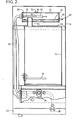
- the boiler is of the self-feeding type having an automatic water supply feed system and comprises an outer casing 10, suitable for bench or counter-top mounting or wall mounting, housing a main boiling chamber 12, an overhead steam condenser vessel 14, and a cistern type fresh water feed tank 16 and other associated components.
- the boiling chamber 12 is provided by a tinned copper tank of generally rectangular form fitted towards the bottom with an inwardly- extending horizontally disposed electric immersion heater element 18 which incorporates a thermal cut-out switch and provides the heating source.
- an outlet tube 20 leads to a draw-off tap 22 at the front which is at a suitable height above a forwardly-projecting base 24 as to permit easy access for filling teapots or other receptacles when the unit is in position on a counter-top.
- an interconnecting pipe 26 providing a communicating passageway for admitting steam leads upwardly into the condenser vessel 14 which is a closed-ended cylindrical vessel, also conveniently made of tinned copper, mounted horizontally above the boiling chamber so that the hollow interior provides a steam collecting and condensing space.
- the steam inlet pipe 26 may be fixed in its upper part to the bottom or base wall of the condenser vessel 14 and may serve to support the latter in position, the lower end being fixed to a top cover 28 of the boiling chamber.
- This top cover 28 is advantageously detachably fitted in place so that it can be removed (as a unit together with the condenser vessel after disconnecting other parts attached thereto) to provide access to the boiling chamber interior for servicing and descaling.
- a steam responsive thermostat sensing element 30 in the form of a slender elongate bulb, which is carried by a mounting grommet 31 in one end wall so as to extend axially in spaced relationship with the walls of the vessel.
- a reduced diameter end section 32a of a water inlet feed pipe 32 is sealed into and passes through the rear wall of the condenser vessel to terminate within the hollow interior in a short nozzle or jet 34 having an orifice aimed towards the sensing element 30.
- the water inlet feed pipe 32 connects to an external fresh water supply system through a main water inlet connector 35 and a normally- closed solenoid operated water inlet control valve 36 located in the lower part of the casing, and incoming water is sprayed under pressure into the condenser vessel interior.
- a substantial proportion of the incoming water sprays directly on to the sensing element 30 and most of the remainder sprays against a significant area of the inner surface of the condenser vessel walls thereby promoting more effective cooling action.
- the upper end of the steam inlet pipe 26 terminates at a level some distance above the base of the condenser vessel, and slightly below this level a water outlet 38 in the far end wall of the condenser vessel leads through an outlet pipe 40 to the feed tank or cistern 16.
- Feed tank 16 forms part of an intermediate feeder arrangement for transfering fresh incoming water from the condenser vessel 14 to the boiling chamber 12 for filling and replenishing the latter, a water outlet 43 in the bottom of this tank being connected to the boiling chamber by way of a delivery pipe 44 having a U-shaped loop (to prevent hot water convection currents) arranged to introduce the fresh water into the boiling chamber at a level slightly above but close to the immersion heater element 18 and below the draw-off tube 20, as ihown.
- the feed tank 16 also contains a level sensor 48, conveniently a pivoted float-operated reed switch device, which sets the maximum Level of water therein, and also the level of water in the boiling chamber with which the feed tank 16 is in hydrostatic equilibrium, by being operatively connected in the electrical energising circuit of the solenoid water supply inlet valve 36.
- the feed tank 16 is also provided with a conventional overflow pipe 50.
- solenoid valve 36 and the other main electrical controls are compactly housed in the lower cooler part of the casing 10 below the boiling chamber 12.
- the water in the boiling chamber is rapidly brought up to the boil, thereby producing steam which passes up through the steam pipe 26 and collects in the condenser vessel.
- the steam sensing thermostat then responds to cause solenoid valve 36 to re-open and hence further water is introduced into the boiling chamber.
- the cycle is then repeated and the net effect is that the level of water in the boiling chamber rises in stages while the temperature is kept close to boiling point ready for draw-off and immediate use until eventually the boiling chamber is filled to its maximum rated capacity.
- the level sensor 48 operates to keep the solenoid inlet valve 36 closed, thereby preventing further inflow of water unless some is first drawn off through tap 22, and the steam responsive thermostat simply cycles to switch the heater element on and off to maintain the temperature.
Landscapes
- Engineering & Computer Science (AREA)
- Food Science & Technology (AREA)
- Apparatus For Making Beverages (AREA)
Applications Claiming Priority (2)
| Application Number | Priority Date | Filing Date | Title |
|---|---|---|---|
| GB838322694A GB8322694D0 (en) | 1983-08-24 | 1983-08-24 | Self-feeding water heating boiler |
| GB8322694 | 1983-08-24 |
Publications (2)
| Publication Number | Publication Date |
|---|---|
| EP0139394A2 true EP0139394A2 (de) | 1985-05-02 |
| EP0139394A3 EP0139394A3 (de) | 1986-11-12 |
Family
ID=10547759
Family Applications (1)
| Application Number | Title | Priority Date | Filing Date |
|---|---|---|---|
| EP84305700A Withdrawn EP0139394A3 (de) | 1983-08-24 | 1984-08-22 | Selbstspeisender Wassererhitzer |
Country Status (2)
| Country | Link |
|---|---|
| EP (1) | EP0139394A3 (de) |
| GB (1) | GB8322694D0 (de) |
Cited By (2)
| Publication number | Priority date | Publication date | Assignee | Title |
|---|---|---|---|---|
| EP0262273A1 (de) * | 1986-09-04 | 1988-04-06 | W.M. STILL & SONS LIMITED | Elektrisches Heizelement zur Erhitzung von Wasser |
| WO2013123159A1 (en) * | 2012-02-14 | 2013-08-22 | Imi Cornelius Inc. | Hot beverage dispensing system |
Family Cites Families (1)
| Publication number | Priority date | Publication date | Assignee | Title |
|---|---|---|---|---|
| GB2076130B (en) * | 1980-04-14 | 1983-11-23 | Zip Heaters Aust Pty Ltd | Boiling water heater |
-
1983
- 1983-08-24 GB GB838322694A patent/GB8322694D0/en active Pending
-
1984
- 1984-08-22 EP EP84305700A patent/EP0139394A3/de not_active Withdrawn
Cited By (2)
| Publication number | Priority date | Publication date | Assignee | Title |
|---|---|---|---|---|
| EP0262273A1 (de) * | 1986-09-04 | 1988-04-06 | W.M. STILL & SONS LIMITED | Elektrisches Heizelement zur Erhitzung von Wasser |
| WO2013123159A1 (en) * | 2012-02-14 | 2013-08-22 | Imi Cornelius Inc. | Hot beverage dispensing system |
Also Published As
| Publication number | Publication date |
|---|---|
| GB8322694D0 (en) | 1983-09-28 |
| EP0139394A3 (de) | 1986-11-12 |
Similar Documents
| Publication | Publication Date | Title |
|---|---|---|
| CN100407971C (zh) | 煮咖啡壶 | |
| US4354094A (en) | Thermostatically controlled electric continuous water heating unit | |
| US6279458B1 (en) | Rapid brew automatic coffee maker | |
| EP0821096B1 (de) | Dampferzeuger für Bügeleisen oder dergleichen | |
| US5743034A (en) | Household steam appliance having a scale-preventing device | |
| US4575615A (en) | Hot water supplying device | |
| JP3323503B2 (ja) | 瞬間温水ディスペンサー | |
| US5131070A (en) | Portable humidifier | |
| US4320702A (en) | Steam generator | |
| US4455477A (en) | Electric boiling water heater | |
| RU2470104C2 (ru) | Парогенератор с секцией для подогрева воды | |
| AU598618B2 (en) | A coffee or tea brewing machine | |
| GB2316299A (en) | Coffee making machine | |
| RU2005115844A (ru) | Устройство для приготовления горячих напитков | |
| EP1221570A2 (de) | Dampferzeugung mit automatischem Wasserbeladungssystem | |
| GB2143031A (en) | Hot water dispenser | |
| EP0139394A2 (de) | Selbstspeisender Wassererhitzer | |
| EP0139395A2 (de) | Wassererhitzer | |
| EP0887588A2 (de) | Automatisches Speisungssystem für Dampferzeuger für elektrische dampfbetriebene Geräte | |
| EP0165907A1 (de) | Maschine zur Herstellung von Espresso-Kaffee, insbesondere für den Haushaltsgebrauch | |
| EP2325381A1 (de) | Dampfgenerator eines Wäschepflegeräts und Wäschepflegerät damit | |
| US5535774A (en) | Apparatus for storing and supplying water for use in catering equipment | |
| AU642445B2 (en) | Heater for liquid | |
| CN210831920U (zh) | 蒸汽发生器及蒸发器 | |
| JP2591618Y2 (ja) | コーヒー沸し器 |
Legal Events
| Date | Code | Title | Description |
|---|---|---|---|
| PUAI | Public reference made under article 153(3) epc to a published international application that has entered the european phase |
Free format text: ORIGINAL CODE: 0009012 |
|
| AK | Designated contracting states |
Designated state(s): BE DE GB IT NL |
|
| PUAL | Search report despatched |
Free format text: ORIGINAL CODE: 0009013 |
|
| AK | Designated contracting states |
Kind code of ref document: A3 Designated state(s): BE DE GB IT NL |
|
| RHK1 | Main classification (correction) |
Ipc: A47J 31/54 |
|
| 17P | Request for examination filed |
Effective date: 19870507 |
|
| 17Q | First examination report despatched |
Effective date: 19880315 |
|
| STAA | Information on the status of an ep patent application or granted ep patent |
Free format text: STATUS: THE APPLICATION IS DEEMED TO BE WITHDRAWN |
|
| 18D | Application deemed to be withdrawn |
Effective date: 19900511 |
|
| RIN1 | Information on inventor provided before grant (corrected) |
Inventor name: DUNCAN, MICHAEL E. |