EP0139445A2 - Montage de commandes pour freins de véhicules - Google Patents
Montage de commandes pour freins de véhicules Download PDFInfo
- Publication number
- EP0139445A2 EP0139445A2 EP84306089A EP84306089A EP0139445A2 EP 0139445 A2 EP0139445 A2 EP 0139445A2 EP 84306089 A EP84306089 A EP 84306089A EP 84306089 A EP84306089 A EP 84306089A EP 0139445 A2 EP0139445 A2 EP 0139445A2
- Authority
- EP
- European Patent Office
- Prior art keywords
- brake
- strut assembly
- pinion
- adjuster
- spindle
- Prior art date
- Legal status (The legal status is an assumption and is not a legal conclusion. Google has not performed a legal analysis and makes no representation as to the accuracy of the status listed.)
- Granted
Links
Images


Classifications
-
- F—MECHANICAL ENGINEERING; LIGHTING; HEATING; WEAPONS; BLASTING
- F16—ENGINEERING ELEMENTS AND UNITS; GENERAL MEASURES FOR PRODUCING AND MAINTAINING EFFECTIVE FUNCTIONING OF MACHINES OR INSTALLATIONS; THERMAL INSULATION IN GENERAL
- F16D—COUPLINGS FOR TRANSMITTING ROTATION; CLUTCHES; BRAKES
- F16D65/00—Parts or details
- F16D65/38—Slack adjusters
- F16D65/40—Slack adjusters mechanical
- F16D65/52—Slack adjusters mechanical self-acting in one direction for adjusting excessive play
- F16D65/56—Slack adjusters mechanical self-acting in one direction for adjusting excessive play with screw-thread and nut
- F16D65/567—Slack adjusters mechanical self-acting in one direction for adjusting excessive play with screw-thread and nut for mounting on a disc brake
-
- F—MECHANICAL ENGINEERING; LIGHTING; HEATING; WEAPONS; BLASTING
- F16—ENGINEERING ELEMENTS AND UNITS; GENERAL MEASURES FOR PRODUCING AND MAINTAINING EFFECTIVE FUNCTIONING OF MACHINES OR INSTALLATIONS; THERMAL INSULATION IN GENERAL
- F16D—COUPLINGS FOR TRANSMITTING ROTATION; CLUTCHES; BRAKES
- F16D55/00—Brakes with substantially-radial braking surfaces pressed together in axial direction, e.g. disc brakes
- F16D55/02—Brakes with substantially-radial braking surfaces pressed together in axial direction, e.g. disc brakes with axially-movable discs or pads pressed against axially-located rotating members
- F16D55/22—Brakes with substantially-radial braking surfaces pressed together in axial direction, e.g. disc brakes with axially-movable discs or pads pressed against axially-located rotating members by clamping an axially-located rotating disc between movable braking members, e.g. movable brake discs or brake pads
- F16D55/224—Brakes with substantially-radial braking surfaces pressed together in axial direction, e.g. disc brakes with axially-movable discs or pads pressed against axially-located rotating members by clamping an axially-located rotating disc between movable braking members, e.g. movable brake discs or brake pads with a common actuating member for the braking members
- F16D55/2245—Brakes with substantially-radial braking surfaces pressed together in axial direction, e.g. disc brakes with axially-movable discs or pads pressed against axially-located rotating members by clamping an axially-located rotating disc between movable braking members, e.g. movable brake discs or brake pads with a common actuating member for the braking members in which the common actuating member acts on two levers carrying the braking members, e.g. tong-type brakes
-
- F—MECHANICAL ENGINEERING; LIGHTING; HEATING; WEAPONS; BLASTING
- F16—ENGINEERING ELEMENTS AND UNITS; GENERAL MEASURES FOR PRODUCING AND MAINTAINING EFFECTIVE FUNCTIONING OF MACHINES OR INSTALLATIONS; THERMAL INSULATION IN GENERAL
- F16D—COUPLINGS FOR TRANSMITTING ROTATION; CLUTCHES; BRAKES
- F16D65/00—Parts or details
- F16D65/14—Actuating mechanisms for brakes; Means for initiating operation at a predetermined position
- F16D65/16—Actuating mechanisms for brakes; Means for initiating operation at a predetermined position arranged in or on the brake
- F16D65/22—Actuating mechanisms for brakes; Means for initiating operation at a predetermined position arranged in or on the brake adapted for pressing members apart, e.g. for drum brakes
-
- F—MECHANICAL ENGINEERING; LIGHTING; HEATING; WEAPONS; BLASTING
- F16—ENGINEERING ELEMENTS AND UNITS; GENERAL MEASURES FOR PRODUCING AND MAINTAINING EFFECTIVE FUNCTIONING OF MACHINES OR INSTALLATIONS; THERMAL INSULATION IN GENERAL
- F16D—COUPLINGS FOR TRANSMITTING ROTATION; CLUTCHES; BRAKES
- F16D2125/00—Components of actuators
- F16D2125/18—Mechanical mechanisms
- F16D2125/58—Mechanical mechanisms transmitting linear movement
- F16D2125/66—Wedges
Definitions
- This invention relates to actuator assemblies for vehicle brakes of the kind in which a brake applying-force from brake-applying means is applied to a braking member through a strut assembly which is guided for axial sliding movement in a longitudinal bore in a housing, and of which the effective length is adjustable, and adjuster means are incorporated for increasing the effective length of the assembly to compensate for wear of friction linings and maintain braking clearances within predetermined limits, the adjuster means incorporating relatively rotatable parts, a spring in which energy is stored in response to relative rotation between said parts when the actuator is operated to apply the brake and after a degree of lost-motion consistent with the desired braking clearances has been taken up, and means for transmitting energy released from the spring to the strut assembly upon release of the brake in order to adjust the effective length of the strut assembly.
- the adjuster means is arranged in parallel with the strut assembly and incorporates the spring in which energy is adapted to be stored, the adjuster means being adapted to receive a signal dependent upon movement of the strut assembly or the brake-applying means in a brake-applying direction, and the adjuster means being adapted to apply an adjusting force to the strut assembly in response to energy released from the spring when the brake is released.
- the signal is applied to the adjuster means through a connection which includes a degree of lost-motion.
- This may comprise back-lash defined by the point at which a toothed rack meshes with a pinion, which rack is movable with the brake-applying means, or it may comprise a pin- and slot connection between the strut assembly and an intermediate point in the length of a lever, of which one end is pivotally connected to a fixed point in the housing and the other acts on the adjuster means.
- the strut assembly comprises inner and outer screw-threaded members, and the outer member meshes with a pinion incorporated in the adjuster means and which is rotatable, when adjustment is required, in order to rotate the outer member relative to the inner, whereby to increase the effective length of the strut assembly.
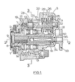
- the actuator assembly illustrated in Figures 1 to 4 of the drawing comprises a strut assembly 1 which is guided to slide in a longitudinal bore 2 in a housing 3 in order to transmit a brake-applying force from a brake actuator 4 to a friction brake member.
- An adjuster mechanism 5 is located in the housing 3 in a bore disposed in a parallel relationship with respect to the bore 2.
- the strut assembly 1 comprises a rotatable internally screw-threaded outer sleeve 7, and a non-rotatable externally screw-threaded inner tappet or thrust member 8 which projects through the outer sleeve 7.
- the thrust member 8 acts at its outer end on a separate thrust plate 9 of increased diameter for applying a brake-applying force to a brake-operating member, and the opposite end of the thrust member 8 is coupled to a re-set member 33.
- a bifurcated wedge 10 having a single inclined face 11 is movable in a direction transverse to the bore 2 in response to operation of the actuator 4, and pairs of rollers 12 and 13 on opposite sides of the strut assembly 1 co-operate between pairs of substantially parallel surfaces, namely an inclined reaction surface 14 on the sleeve 7, and a planar surface 15 on a reaction member 16 through which the strut assembly 1 projects rearwardly.
- movement of the wedge 10 in a direction to oppose the force in a return spring 17, reacts against the surface 15, and is operative to advance the strut assembly 1 in the bore 2 to apply the brake.
- the adjuster mechanism 5 comprises a spindle 20 which is journalled for rotation at opposite ends in counterbores 21 and 22 at opposite ends of the bore in which the mechanism 5 is housed.
- a first pinion 23 is journalled for rotation on the spindle 20 through a one-way drive 24, and a second pinion 25 has a screw-threaded engagement with a fast-thread on a portion 26 of the spindle 20 which is of increased diameter.
- the first pinion 23 is adapted to mesh with a toothed rack formation 27 on the adjacent end face of the wedge 10 when adjustment is required to compensate for wear of the linings of the friction member.
- the second pinion 25 permanently meshes with the teeth 18 on the outer face of the sleeve 7, and the teeth are arranged linearly so that the sleeve 7 can move axially without imparting any rotation to the pinion 25.
- a compression spring 28 acts through a bearing 29 normally to urge the pinion 25 against an end face 30 on the housing 3.
- the spindle 20 is journalled in the counterbore 22 through a one-way drive 31 and is urged towards the closed end of the counterbore 22 by a compression spring 19 housed in the counterbore 21.
- the re-set member 33 In order to re-set the strut assembly 1 to permit replacement of brake linings the re-set member 33 is accessible from the end of the housing 3 remote f r on. the thrust plate 9.
- the re-set member 33 comprises a spindle 34 which is journalled for rotation in the housing 3 and has a splined or other slidably keyed engagement in an axial bore 35 in the thrust member 8 and, at its outer end, carries a head 36 in the peripheral edge of which is provided a series of angularly spaced recesses 37, in any one of which a spring loaded peg 38 can be received to hold the thrust member 8 against rotation in any desired position, relative to the plate 9.
- Rotation of the head 36 screws the thrust member 8 relative to the sleeve 7 in order to alter the effective length of the thrust assembly 1 with the sleeve 7 being held against rotation by its engagement with the pinion 25 and the effect of the one-way drive 31.
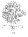
- the actuator assembly illustrated in Figures 5 to 8 of the drawings comprises a housing 40 having a longitudinally extending open-ended bore 41 which is traversed by a transfer chamber 42 in which is housed a wedge-expander assembly 43.
- a pair of oppositely-acting strut assemblies 44, 45 work in the bore 41 and their inner ends are adapted to be separated to urge them outwardly to apply the brake by movement of the wedge assembly 43 in a transverse direction. This is achieved by operation of an actuator 46 and against the force in a return spring 47.
- Each strut assembly 44, 45 comprises a rotatable internally screw-threaded outer sleeve 48 which is guided to slide in the bore 41, and a non-rotatable externally screw-threaded inner tappet 49 which is held against rotation by the engagement with caliper brake levers (not shown).
- the wedge assembly 43 comprises a wedge 50 which acts on inclined faces of members 39, in turn acting on the inner ends of the sleeves 48 through caged rollers 51 in order to separate the adjacent ends simultaneously.
- the sleeves 48 are rotable relative to the members 39 with the inclined faces.
- the rollers 51 are received in slots in the ends of the members, in order to hold the members against rotation.
- An adjuster mechanism 52 is mounted in parallel with the bore 41 in a chamber defined within an end-cap 53 detachably secured to the housing 40.
- the adjuster mechanism 52 comprises a longitudinally extending spindle 54 which is mounted against rotation.
- a pair of externally screw-threaded members 55 and 56 are mounted for rotation on spaced portions of the spindle 54 through one-way drives 57 and 58 respectively, and the drives 57 and 58 are so arranged that each member 55 and 56 is rotatable with respect to the spindle 54 in one direction only.
- Respective pinions 59, 60 are screw-threadably mounted on the respective members 55, 56.
- Each pinion 59, 60 has a linear tooth formation meshing with a similar linear tooth formation 61, 62 on a respective one of the sleeves 48, and is normally urged inwardly by a compression spring 63, 64 which acts on it through a bearing 65.
- the pinions 59, 60 have oppositely arranged adjacent thrust faces 66, 67 upon each of which acts the outer ends of a lever 68 of generally H outline of which the inner end is pivotally connected to the housing 40 by a transverse pivot pin 69, and at an intermediate point in the length of its limbs carries oppositely directed pins 70 which are received in diametrically opposed elongate slots 71 in the sleeve 48.
- the clearance between the pin 70 and the end of the respective slot 71 determine the braking clearance for the respective braking member on that side of the brake.
- the lever 68 will be moved angularly to engage with the thrust face 67 on the pinion 60, in turn to move the pinion 60 axially, with the teeth sliding axially with respect to the teeth on the sleeve 48. Resulting from the direction of the drive 58, the member 56 is rotated on the spindle 54 with the spring 64 being compressed to store energy in it.
- the lever 68 Upon release of the brake, the lever 68 is moved angularly in the opposite direction and the energy is released from the spring 64 to urge the pinion 60 axially in the opposite direction.
- the pinion 60 is rotated as it moves axially. This, in turn, causes the sleeve 48 to be rotated relative to the tappet 49 to increase the effective length of the strut assembly 45 and maintain the braking clearances within the desired limits.
- the effective lengths of the two strut assemblies 44, 45 are adjustable independently of each other in accordance with the required braking clearances of the respective braking members.
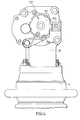
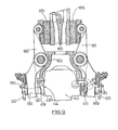
- the actuator assembly of Figures 5 to 8 is adapted to actuate a disc brake for a rail vehicle.
- the brake comprises a pair of caliper levers 80, 81 which are pivotally mounted at intermediate points in their lengths on a stationary member 82.
- the levers 80, 81 straddle the peripheral edge of a rotatable disc 83 to be braked.
- the levers 80, 81 at their inner ends carry friction pad assemblies 85, 86 for engagement with opposite faces of the disc 83 and, in a conventional manner, the drag on the pad assemblies 85, 86, when the brake is applied, is taken by the stationary member 82.
- the actuator assembly 40 is mounted on the stationary member 82 between the outer ends of the levers 80, 81 so that operation of the actuator assembly separates the levers 80, 81 at their outer ends, in turn to urge the inner ends towards each other to apply the pad assemblies 85, 86 to the disc 83.
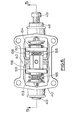
- each spindle 88, 89 is of stepped outline having an integral head 90 of increased diameter at its inner end.
- the head 90 bears against the inner face of the respective lever and is provided with tongue 91 which is received within a slot in the head of the tappet 49, and is of arcuate outline to define a rolling engagement with the base of the slot in the tappet.
- the outer ends of the spindles 88, 89 project from the levers 80, 81 and carry heads 92, 93. Each head 92, 93 is fast with its spindle.
- the peripheral edges of the heads 92 and 93 are provided with angularly spaced recesses 94, in any one of which a spring-loaded peg 95 can be received to hold the respective spindle 88, 89 against rotation relative to the respective lever 80, 81.
- the pegs 95 When the brake is initially assembled, the pegs 95 are released from the recesses 94 against their spring- loadings, and the heads 92 and 93 are rotated independently of each other to adjust the effective lengths of the strut assemblies 44 and 45 in order to set the brake clearances at desired values. The pegs 95 are then engaged with the heads 92 and 93 to hold the spindles 88, 89, and in consequence the tappets 49, against rotation.
- the adjuster mechanism 52 is operative, as described above, to maintain the loading clearances at predetermined levels.
- the pegs 95 When it becomes necessary to replace the pad assemblies 85 and 86, before or after removal of worn assemblies the pegs 95 are first released, and the heads 92, 93 are then rotated to reduce the effective lengths of the strut assemblies 44, 45 thereby increasing the spacing between the inner ends of the levers 80 and 81 by an amount sufficient to receive the new pac assemblies. After the new assemblies have been fitted, the heads 92 and 93 can then be rotated in the opposite direction to set the braking clearances as described above.
Landscapes
- Engineering & Computer Science (AREA)
- General Engineering & Computer Science (AREA)
- Mechanical Engineering (AREA)
- Braking Arrangements (AREA)
Applications Claiming Priority (2)
| Application Number | Priority Date | Filing Date | Title |
|---|---|---|---|
| GB838324942A GB8324942D0 (en) | 1983-09-17 | 1983-09-17 | Actuator assemblies for vehicle brakes |
| GB8324942 | 1983-09-17 |
Publications (3)
| Publication Number | Publication Date |
|---|---|
| EP0139445A2 true EP0139445A2 (fr) | 1985-05-02 |
| EP0139445A3 EP0139445A3 (en) | 1985-11-06 |
| EP0139445B1 EP0139445B1 (fr) | 1988-03-23 |
Family
ID=10548940
Family Applications (1)
| Application Number | Title | Priority Date | Filing Date |
|---|---|---|---|
| EP84306089A Expired EP0139445B1 (fr) | 1983-09-17 | 1984-09-06 | Montage de commandes pour freins de véhicules |
Country Status (5)
| Country | Link |
|---|---|
| US (1) | US4567966A (fr) |
| EP (1) | EP0139445B1 (fr) |
| DE (1) | DE3470019D1 (fr) |
| GB (2) | GB8324942D0 (fr) |
| IN (1) | IN162334B (fr) |
Cited By (7)
| Publication number | Priority date | Publication date | Assignee | Title |
|---|---|---|---|---|
| EP0240125A1 (fr) * | 1986-03-05 | 1987-10-07 | LUCAS INDUSTRIES public limited company | Mécanisme d'actionnement de frein à coin et rouleaux |
| FR2602289A1 (fr) * | 1986-07-30 | 1988-02-05 | Bendix France | Mecanisme d'actionnement de frein a tambour, a commande par coin et frein a tambour le comportant |
| EP0262866A3 (fr) * | 1986-10-03 | 1989-02-08 | LUCAS INDUSTRIES public limited company | Mécanisme d'actionnement de frein |
| WO1997001045A1 (fr) * | 1995-06-20 | 1997-01-09 | Lucas Industries Public Limited Company | Frein a disque |
| WO2008015569A3 (fr) * | 2006-07-31 | 2008-05-29 | Poli Costruzione Materiali Tra | Unité de disque de frein compacte pour véhicules sur rails |
| EP2037146A3 (fr) * | 2007-09-13 | 2009-04-29 | Akebono Brake Industry CO., LTD. | Mécanisme de pression et d'actionnement d'un dispositif de frein à disque |
| CN101387324B (zh) * | 2007-09-13 | 2011-06-29 | 曙制动器工业株式会社 | 盘式制动装置的推压动作机构 |
Families Citing this family (6)
| Publication number | Priority date | Publication date | Assignee | Title |
|---|---|---|---|---|
| FR2573498B1 (fr) * | 1984-11-21 | 1987-02-27 | Bendix France | Frein a disque |
| DE59301481D1 (de) | 1992-05-05 | 1996-02-29 | Lucas Ind Plc | Betätigungsvorrichtung mit selbsttätiger nachstellung an scheibenbremsen, insbesondere für lastkraftwagen und omnibusse |
| DE4307018A1 (de) † | 1993-03-05 | 1994-09-08 | Perrot Bremse Gmbh Deutsche | Nachstellvorrichtung für eine Scheibenbremse |
| US5664646A (en) * | 1993-06-02 | 1997-09-09 | Bejot; Philippe | Disc brake, especially for vehicles |
| US7591349B2 (en) * | 2005-10-31 | 2009-09-22 | Warner Electric Technology Llc | Liquid cooled brake assembly |
| DE102012008574B4 (de) * | 2012-04-27 | 2016-09-22 | Knorr-Bremse Systeme für Nutzfahrzeuge GmbH | Pneumatisch oder elektromechanisch betätigbare Scheibenbremse |
Family Cites Families (6)
| Publication number | Priority date | Publication date | Assignee | Title |
|---|---|---|---|---|
| US3653470A (en) * | 1970-09-18 | 1972-04-04 | Gen Motors Corp | Disc brake with hydraulic and mechanical actuation and wear adjustment means |
| GB1458361A (en) * | 1973-01-05 | 1976-12-15 | Girling Ltd | Vehicle brakes |
| DE2300876C3 (de) * | 1973-01-09 | 1981-05-07 | Knorr-Bremse GmbH, 8000 München | Anordnung einer Betätigungsvorrichtung für Fahrzeugbremsen, insbesondere für Schienenfahrzeuge |
| AU532897B2 (en) * | 1978-11-07 | 1983-10-20 | Lucas Industries Limited | Brake actuators |
| US4416356A (en) * | 1980-09-27 | 1983-11-22 | Automotive Products Limited | Hydraulic wheel cylinder assemblies and drum brakes incorporating same |
| US4394890A (en) * | 1981-08-03 | 1983-07-26 | Eaton Corporation | Automatic slack adjuster |
-
1983
- 1983-09-17 GB GB838324942A patent/GB8324942D0/en active Pending
-
1984
- 1984-09-04 IN IN673/MAS/84A patent/IN162334B/en unknown
- 1984-09-05 GB GB08422395A patent/GB2146718B/en not_active Expired
- 1984-09-06 DE DE8484306089T patent/DE3470019D1/de not_active Expired
- 1984-09-06 EP EP84306089A patent/EP0139445B1/fr not_active Expired
- 1984-09-06 US US06/648,008 patent/US4567966A/en not_active Expired - Fee Related
Cited By (14)
| Publication number | Priority date | Publication date | Assignee | Title |
|---|---|---|---|---|
| EP0240125A1 (fr) * | 1986-03-05 | 1987-10-07 | LUCAS INDUSTRIES public limited company | Mécanisme d'actionnement de frein à coin et rouleaux |
| FR2602289A1 (fr) * | 1986-07-30 | 1988-02-05 | Bendix France | Mecanisme d'actionnement de frein a tambour, a commande par coin et frein a tambour le comportant |
| EP0255428A3 (en) * | 1986-07-30 | 1988-11-09 | Bendix France Societe Anonyme Dite: | Wedge actuator for drum brake and drum brake provided with it |
| EP0262866A3 (fr) * | 1986-10-03 | 1989-02-08 | LUCAS INDUSTRIES public limited company | Mécanisme d'actionnement de frein |
| WO1997001045A1 (fr) * | 1995-06-20 | 1997-01-09 | Lucas Industries Public Limited Company | Frein a disque |
| EP1013958A3 (fr) * | 1995-06-20 | 2000-08-16 | Meritor Automotive Inc. | Frein et son actionneur |
| WO2008015569A3 (fr) * | 2006-07-31 | 2008-05-29 | Poli Costruzione Materiali Tra | Unité de disque de frein compacte pour véhicules sur rails |
| JP2009545712A (ja) * | 2006-07-31 | 2009-12-24 | ポリ コストルツィオーネ マテリアリ トラツィオーネ エス.アール.エル. ショートリー ポリ エス.アール.エル. | レール上の車両用小型ディスクブレーキユニット |
| RU2431067C2 (ru) * | 2006-07-31 | 2011-10-10 | Поли Коструционе Материали Трационе С.р.л. | Компактный дисковый тормозной блок для рельсового транспортного средства |
| AU2007280090B2 (en) * | 2006-07-31 | 2011-11-03 | Poli Costruzione Materiali Trazione S.R.L. Shortly Poli S.R.L. | Compact disc-brake unit for vehicles on rails |
| CN101523074B (zh) * | 2006-07-31 | 2012-03-21 | 普利建筑牵引材料有限责任公司(简称:普利有限责任公司) | 用于轨道上的车辆的紧凑型盘式制动器单元 |
| US8794393B2 (en) | 2006-07-31 | 2014-08-05 | POLI Costruzione Materiali Trazione S.R.L. | Compact disc-brake unit for vehicles on rails |
| EP2037146A3 (fr) * | 2007-09-13 | 2009-04-29 | Akebono Brake Industry CO., LTD. | Mécanisme de pression et d'actionnement d'un dispositif de frein à disque |
| CN101387324B (zh) * | 2007-09-13 | 2011-06-29 | 曙制动器工业株式会社 | 盘式制动装置的推压动作机构 |
Also Published As
| Publication number | Publication date |
|---|---|
| GB2146718A (en) | 1985-04-24 |
| DE3470019D1 (en) | 1988-04-28 |
| GB2146718B (en) | 1986-07-02 |
| EP0139445B1 (fr) | 1988-03-23 |
| US4567966A (en) | 1986-02-04 |
| GB8422395D0 (en) | 1984-10-10 |
| GB8324942D0 (en) | 1983-10-19 |
| EP0139445A3 (en) | 1985-11-06 |
| IN162334B (fr) | 1988-04-30 |
Similar Documents
| Publication | Publication Date | Title |
|---|---|---|
| EP0139445B1 (fr) | Montage de commandes pour freins de véhicules | |
| EP0291071B1 (fr) | Frein à disque pour véhicules | |
| US2669327A (en) | Automatic clearance adjusting mechanism for single-disk, spot-type brakes | |
| US5582273A (en) | Compressed-air disc brake | |
| EP1160476A2 (fr) | Mécanisme de frein pour frein à disque | |
| US4382491A (en) | Drag free disc brake assembly having automatically adjusting caliper | |
| GB1442562A (en) | Mechanically actuated disc brake | |
| EP0070106A1 (fr) | Frein à disque | |
| EP0139518A2 (fr) | Ensemble d'actionnement hydraulique pour freins de véhicule | |
| EP0243114B1 (fr) | Freins à disque | |
| US3318421A (en) | Brake adjusting system | |
| US4623046A (en) | Automatic adjuster for duo-servo internal shoe drum brakes | |
| US3460653A (en) | Brake adjuster | |
| DE2131535B2 (de) | Selbsttaetige mechanische nachstellvorrichtung fuer eine innenbackenbremse | |
| US4026394A (en) | Vehicle shoe-drum brakes of the duo-servo type | |
| US3482661A (en) | Automatic self-adjusting mechanism for disk brakes | |
| US3913708A (en) | Disc brake assemblies for vehicles | |
| US4986394A (en) | Brake actuator | |
| US4344510A (en) | Disc brake and improved adjuster therefor | |
| US7857109B2 (en) | Adjustable cam actuated brake assembly | |
| DE2141430B2 (de) | Teilbelagscheibenbremse | |
| JPH0146737B2 (fr) | ||
| GB1326632A (en) | Disc brakes | |
| US3882974A (en) | Automatic slack adjuster for a vehicle brake | |
| US3314506A (en) | Caliper type, spot disc brake |
Legal Events
| Date | Code | Title | Description |
|---|---|---|---|
| PUAI | Public reference made under article 153(3) epc to a published international application that has entered the european phase |
Free format text: ORIGINAL CODE: 0009012 |
|
| 17P | Request for examination filed |
Effective date: 19841208 |
|
| AK | Designated contracting states |
Designated state(s): DE FR |
|
| PUAL | Search report despatched |
Free format text: ORIGINAL CODE: 0009013 |
|
| AK | Designated contracting states |
Designated state(s): DE FR |
|
| 17Q | First examination report despatched |
Effective date: 19870616 |
|
| GRAA | (expected) grant |
Free format text: ORIGINAL CODE: 0009210 |
|
| AK | Designated contracting states |
Kind code of ref document: B1 Designated state(s): DE FR |
|
| REF | Corresponds to: |
Ref document number: 3470019 Country of ref document: DE Date of ref document: 19880428 |
|
| ET | Fr: translation filed | ||
| PLBE | No opposition filed within time limit |
Free format text: ORIGINAL CODE: 0009261 |
|
| STAA | Information on the status of an ep patent application or granted ep patent |
Free format text: STATUS: NO OPPOSITION FILED WITHIN TIME LIMIT |
|
| 26N | No opposition filed | ||
| PGFP | Annual fee paid to national office [announced via postgrant information from national office to epo] |
Ref country code: FR Payment date: 19910906 Year of fee payment: 8 |
|
| PGFP | Annual fee paid to national office [announced via postgrant information from national office to epo] |
Ref country code: DE Payment date: 19910930 Year of fee payment: 8 |
|
| REG | Reference to a national code |
Ref country code: FR Ref legal event code: TP |
|
| PG25 | Lapsed in a contracting state [announced via postgrant information from national office to epo] |
Ref country code: FR Effective date: 19930528 |
|
| REG | Reference to a national code |
Ref country code: FR Ref legal event code: ST |
|
| PG25 | Lapsed in a contracting state [announced via postgrant information from national office to epo] |
Ref country code: DE Effective date: 19931201 |