EP0139451A1 - Porte-balai - Google Patents
Porte-balai Download PDFInfo
- Publication number
- EP0139451A1 EP0139451A1 EP84306139A EP84306139A EP0139451A1 EP 0139451 A1 EP0139451 A1 EP 0139451A1 EP 84306139 A EP84306139 A EP 84306139A EP 84306139 A EP84306139 A EP 84306139A EP 0139451 A1 EP0139451 A1 EP 0139451A1
- Authority
- EP
- European Patent Office
- Prior art keywords
- brush
- end wall
- brush box
- box
- tongue
- Prior art date
- Legal status (The legal status is an assumption and is not a legal conclusion. Google has not performed a legal analysis and makes no representation as to the accuracy of the status listed.)
- Granted
Links
- 244000185238 Lophostemon confertus Species 0.000 title claims abstract description 40
- 239000000463 material Substances 0.000 claims abstract description 6
- 238000005452 bending Methods 0.000 description 6
- 238000012423 maintenance Methods 0.000 description 2
- 238000004519 manufacturing process Methods 0.000 description 2
- 239000002184 metal Substances 0.000 description 2
- 238000000034 method Methods 0.000 description 2
- 238000010276 construction Methods 0.000 description 1
- 229920003023 plastic Polymers 0.000 description 1
- 239000004033 plastic Substances 0.000 description 1
Images

Classifications
-
- H—ELECTRICITY
- H01—ELECTRIC ELEMENTS
- H01R—ELECTRICALLY-CONDUCTIVE CONNECTIONS; STRUCTURAL ASSOCIATIONS OF A PLURALITY OF MUTUALLY-INSULATED ELECTRICAL CONNECTING ELEMENTS; COUPLING DEVICES; CURRENT COLLECTORS
- H01R39/00—Rotary current collectors, distributors or interrupters
- H01R39/02—Details for dynamo electric machines
- H01R39/36—Connections of cable or wire to brush
-
- H—ELECTRICITY
- H01—ELECTRIC ELEMENTS
- H01R—ELECTRICALLY-CONDUCTIVE CONNECTIONS; STRUCTURAL ASSOCIATIONS OF A PLURALITY OF MUTUALLY-INSULATED ELECTRICAL CONNECTING ELEMENTS; COUPLING DEVICES; CURRENT COLLECTORS
- H01R39/00—Rotary current collectors, distributors or interrupters
- H01R39/02—Details for dynamo electric machines
- H01R39/38—Brush holders
-
- H—ELECTRICITY
- H02—GENERATION; CONVERSION OR DISTRIBUTION OF ELECTRIC POWER
- H02K—DYNAMO-ELECTRIC MACHINES
- H02K5/00—Casings; Enclosures; Supports
- H02K5/04—Casings or enclosures characterised by the shape, form or construction thereof
- H02K5/14—Means for supporting or protecting brushes or brush holders
- H02K5/143—Means for supporting or protecting brushes or brush holders for cooperation with commutators
- H02K5/148—Slidably supported brushes
-
- H—ELECTRICITY
- H02—GENERATION; CONVERSION OR DISTRIBUTION OF ELECTRIC POWER
- H02K—DYNAMO-ELECTRIC MACHINES
- H02K2205/00—Specific aspects not provided for in the other groups of this subclass relating to casings, enclosures, supports
- H02K2205/06—Machines characterised by means for keeping the brushes in a retracted position during assembly
Definitions
- This invention relates to brush boxes and to electric motors incorporating such brush boxes.
- a brush box made of sheet material and including side walls, an end wall and an opening opposite the end wall, wherein the end wall is connected to one of the side walls by a tongue of sheet material and the end wall can be moved from a closed position in which it obstructs the associated end of the brush box to an open position in which the obstruction is substantially removed to enable a brush to be inserted or removed, movement of the end wall being accompanied by deformation of the tongue.
- the tongue provides a substantial length along which deformation can take place and thus the bending strain at any one location is reduced so that the end wall can be moved repeatedly between the open and closed positions without danger of it breaking off.
- the tongue preferably has a length of at least one sixth of the length of the brush box.
- the tongue may be formed from a part of the side wall to which the end wall is joined.
- the invention also provides an electric motor including a rotor, a brush box as defined above and a brush housed in the brush box and resiliently biased away from the end wall into contact with the rotor.
- a hedge trimmer has an outer casing 1 of clam shell construction, a motor 2 connectible to a power supply by a cable 3 via a switch 4 in a handle 5.
- the motor has an armature shaft 6 which drives the blades (not shown) of the trimmer via gears (not shown) mounted in a gearbox housing 7.
- the motor 2 has an armature on the armature shaft 6, a commutator 8, a stator assembly 9, an end cap 10 at the gearbox end and an end cap assembly 11 at the commutator end.
- the end cap 10, end cap assembly 11 and stator assembly 9 are bolted together and the end cap 10 and the gearbox housing 7 are also bolted together.
- the armature shaft is mounted for rotation at one end in a bearing of the end cap assembly 11 and at the other end in a bearing in the gearbox housing 7.
- the present invention is concerned primarily with the structure of brush boxes that are mounted on the end cap assembly 11 and it should be understood that the invention may find a wide variety of applications in any case where a brush box is to be employed. The description below is therefore concerned primarily with details of the brush boxes.
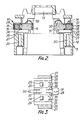
- the end cap assembly 11 comprises a plastics body 12, a bearing 13 in which the motor armature shaft is mounted and a pair of brush boxes 14 housing brushes 15 biased towards the armature shaft by springs 16.
- Strip connectors for making electrical connection between the brush boxes and ends of the field coils of the motor 2, and other strip connectors for making electrical connection between a power supply and ends of the field coils are provided, but these are not shown in Fig. 2.
- the strip connectors are relatively stiff members and therefore retain their shape during normal use.
- the end of the body 12 fits around the end of the stator assembly 9 and has screw threaded bores 20 by which it is bolted to the stator assembly and the end cap 10.
- the brush boxes 14 are made by folding sheet metal blanks which are of the form shown in Fig. 3. Referring now to Figs. 2 and 3 each box has a top wall 22, side walls 23 and 24, an end wall 28 with an integral projection 31, a slotted base made up of portions 25 of the blank, legs 26 and feet 27 which extend outwardly from the legs 26.
- Each side wall of the brush box has a wing 29 which during manufacture of the box is bent through a small angle so that it projects outwardly from the box.
- a terminal 32 is formed on each side wall by bending a portion of the wall out to a position substantially perpendicular to the wall. In use, strip connectors are connected to the brush boxes 14 by connection to the terminals 32.
- the brush box is first bent into the shape of the right hand brush box shown in Fig. 2.
- the top wall includes an extension 30 which is flat when formed in the blank of Fig. 3 but which is bent into a hook shape above the hollow interior of the box.
- the brush 15 and metal spring 16 is inserted into the brush box 14 through the open end opposite the end wall 28 with the spring between the brush 15 and a wall 28.
- the brush is then pushed into the box against the bias of the spring until the brush is entirely within the box.
- the hooked extension 30 is then bent down to the position shown on the left hand side of Fig. 2 in which position it acts as a fastening and retains the brush entirely within the brush box.
- the brush box and brush assembly is then installed on the body 12 by pushing the boxes into position in a direction perpendicular to and directly towards the motor axis.
- the feet 27 of each brush box are slid along a groove in the body 12 and as the box reaches the limit of its inward movement, the wings 29 on the box pass hooks formed on the body 12 and spring outwards preventing reverse movement of the brush box.
- the hooked extensions 30 are bent up into the position shown on the right hand side of Fig. 2 allowing the brushes to move out from the brush boxes under their spring bias into contact with the commutator.
- the end wall 28 of the brush box is bent upwards. It has been found in the past that repeated bending of the end wall leads to its breaking off at the junction with the top wall 22.
- slots 36 are provided in the top wall extending from its junction with the wall 28 so that a tongue is defined along a part of the top wall and bending of the end wall relative to the top wall can be accommodated over a much greater length by deformation of this tongue resulting in lower bending strains and improving the resistance of the box to repeated replacement of brushes.
- the tongue extends along about a quarter of the length of the top wall 22.
- end cap assembly 11 is also described in the specification of our co-pending European patent application filed on the same date as this application and entitled "Improvements in or relating to electric motors". That specification also includes description of other embodiments of motor and the contents of that specification is incorporated herein by reference.
Landscapes
- Engineering & Computer Science (AREA)
- Power Engineering (AREA)
- Motor Or Generator Frames (AREA)
Applications Claiming Priority (2)
| Application Number | Priority Date | Filing Date | Title |
|---|---|---|---|
| GB8324263 | 1983-09-09 | ||
| GB838324263A GB8324263D0 (en) | 1983-09-09 | 1983-09-09 | Electric motors |
Publications (2)
| Publication Number | Publication Date |
|---|---|
| EP0139451A1 true EP0139451A1 (fr) | 1985-05-02 |
| EP0139451B1 EP0139451B1 (fr) | 1987-10-21 |
Family
ID=10548586
Family Applications (1)
| Application Number | Title | Priority Date | Filing Date |
|---|---|---|---|
| EP84306139A Expired EP0139451B1 (fr) | 1983-09-09 | 1984-09-07 | Porte-balai |
Country Status (4)
| Country | Link |
|---|---|
| EP (1) | EP0139451B1 (fr) |
| DE (1) | DE3466915D1 (fr) |
| GB (1) | GB8324263D0 (fr) |
| ZA (1) | ZA846892B (fr) |
Cited By (5)
| Publication number | Priority date | Publication date | Assignee | Title |
|---|---|---|---|---|
| EP0322832A1 (fr) * | 1987-12-30 | 1989-07-05 | Kress-elektrik GmbH + Co. Elektromotorenfabrik | Moteur électrique universel |
| WO1995008855A1 (fr) * | 1993-09-20 | 1995-03-30 | Itt Industries, Inc. | Porte-balai dynamoelectrique |
| WO1996027925A1 (fr) * | 1995-03-07 | 1996-09-12 | The Whitaker Corporation | Ensemble moteur electrique et contact afferent |
| DE19602173A1 (de) * | 1996-01-23 | 1997-10-16 | Teves Gmbh Alfred | Elektromotorgehäuse |
| DE19643522A1 (de) * | 1996-10-22 | 1998-04-23 | Teves Gmbh Alfred | Elektromotor |
Citations (4)
| Publication number | Priority date | Publication date | Assignee | Title |
|---|---|---|---|---|
| GB1151636A (en) * | 1966-02-24 | 1969-05-14 | Electrolux Ab | Brush Holder for an Electric Commutator Motor |
| US4074162A (en) * | 1976-06-24 | 1978-02-14 | Dynamics Corporation Of America | Brush spring assembly |
| DE2819352A1 (de) * | 1978-05-03 | 1979-11-15 | Bosch Gmbh Robert | Vorrichtung zum auswechseln von federbelasteten kohlebuersten fuer elektrische maschinen |
| US4266155A (en) * | 1979-09-10 | 1981-05-05 | The Singer Company | Brush holder assembly |
Family Cites Families (1)
| Publication number | Priority date | Publication date | Assignee | Title |
|---|---|---|---|---|
| US3924147A (en) * | 1974-01-02 | 1975-12-02 | Barber Colman Co | Brushholders and ancillary components mounted on a printed circuit board |
-
1983
- 1983-09-09 GB GB838324263A patent/GB8324263D0/en active Pending
-
1984
- 1984-09-03 ZA ZA846892A patent/ZA846892B/xx unknown
- 1984-09-07 EP EP84306139A patent/EP0139451B1/fr not_active Expired
- 1984-09-07 DE DE8484306139T patent/DE3466915D1/de not_active Expired
Patent Citations (4)
| Publication number | Priority date | Publication date | Assignee | Title |
|---|---|---|---|---|
| GB1151636A (en) * | 1966-02-24 | 1969-05-14 | Electrolux Ab | Brush Holder for an Electric Commutator Motor |
| US4074162A (en) * | 1976-06-24 | 1978-02-14 | Dynamics Corporation Of America | Brush spring assembly |
| DE2819352A1 (de) * | 1978-05-03 | 1979-11-15 | Bosch Gmbh Robert | Vorrichtung zum auswechseln von federbelasteten kohlebuersten fuer elektrische maschinen |
| US4266155A (en) * | 1979-09-10 | 1981-05-05 | The Singer Company | Brush holder assembly |
Cited By (6)
| Publication number | Priority date | Publication date | Assignee | Title |
|---|---|---|---|---|
| EP0322832A1 (fr) * | 1987-12-30 | 1989-07-05 | Kress-elektrik GmbH + Co. Elektromotorenfabrik | Moteur électrique universel |
| WO1995008855A1 (fr) * | 1993-09-20 | 1995-03-30 | Itt Industries, Inc. | Porte-balai dynamoelectrique |
| US5495134A (en) * | 1993-09-20 | 1996-02-27 | Itt Automotive Electrical Systems Inc. | Dynamoelectric brush holder |
| WO1996027925A1 (fr) * | 1995-03-07 | 1996-09-12 | The Whitaker Corporation | Ensemble moteur electrique et contact afferent |
| DE19602173A1 (de) * | 1996-01-23 | 1997-10-16 | Teves Gmbh Alfred | Elektromotorgehäuse |
| DE19643522A1 (de) * | 1996-10-22 | 1998-04-23 | Teves Gmbh Alfred | Elektromotor |
Also Published As
| Publication number | Publication date |
|---|---|
| GB8324263D0 (en) | 1983-10-12 |
| DE3466915D1 (en) | 1987-11-26 |
| EP0139451B1 (fr) | 1987-10-21 |
| ZA846892B (en) | 1985-04-24 |
Similar Documents
| Publication | Publication Date | Title |
|---|---|---|
| EP0142237B1 (fr) | Composants pour moteurs électriques | |
| US4513214A (en) | Dynamoelectric machine | |
| GB2137821A (en) | An electric motor and method of assembling same | |
| EP0322832B1 (fr) | Moteur électrique universel | |
| US6717322B2 (en) | Motor housing having simplified cover plate and brush base | |
| US5793141A (en) | Plug-in modular brush cartridge | |
| US6479916B1 (en) | Method and apparatus for mounting electronic motor controls | |
| EP0139451B1 (fr) | Porte-balai | |
| US6909218B2 (en) | End cap and brush box assembly | |
| CN86108476A (zh) | 带电刷装置的小型旋转机构 | |
| US4677333A (en) | Brush holder mountable in recess of peripheral wall of electric machine | |
| US4574471A (en) | Methods of assembling components of an electric motor | |
| US4983872A (en) | Brush gear for a permanent magnet motor | |
| US4684774A (en) | Electrical contacts for a switch | |
| GB2094561A (en) | Electric motor brush gear | |
| US4558189A (en) | Reversing switch | |
| WO2024218052A1 (fr) | Moteur électrique et compresseur réfrigérant comprenant un tel moteur électrique | |
| US4931682A (en) | Shimless/groundless dynamoelectric machine | |
| EP0338741A3 (fr) | Collecteur pour un moteur électrique | |
| GB2207292A (en) | Electric motor | |
| GB2214358A (en) | A brush leaf assembly for electric motor | |
| GB2142192A (en) | Electric motor | |
| KR880001461Y1 (ko) | 송풍기 | |
| GB2203292A (en) | Suppressor connection for commutator segment | |
| CN85203067U (zh) | 电刷装置微型旋转机械 |
Legal Events
| Date | Code | Title | Description |
|---|---|---|---|
| PUAI | Public reference made under article 153(3) epc to a published international application that has entered the european phase |
Free format text: ORIGINAL CODE: 0009012 |
|
| 17P | Request for examination filed |
Effective date: 19841220 |
|
| AK | Designated contracting states |
Designated state(s): DE FR GB IT |
|
| 17Q | First examination report despatched |
Effective date: 19860429 |
|
| GRAA | (expected) grant |
Free format text: ORIGINAL CODE: 0009210 |
|
| AK | Designated contracting states |
Kind code of ref document: B1 Designated state(s): DE FR GB IT |
|
| PG25 | Lapsed in a contracting state [announced via postgrant information from national office to epo] |
Ref country code: IT Free format text: LAPSE BECAUSE OF FAILURE TO SUBMIT A TRANSLATION OF THE DESCRIPTION OR TO PAY THE FEE WITHIN THE PRESCRIBED TIME-LIMIT;WARNING: LAPSES OF ITALIAN PATENTS WITH EFFECTIVE DATE BEFORE 2007 MAY HAVE OCCURRED AT ANY TIME BEFORE 2007. THE CORRECT EFFECTIVE DATE MAY BE DIFFERENT FROM THE ONE RECORDED. Effective date: 19871021 |
|
| REF | Corresponds to: |
Ref document number: 3466915 Country of ref document: DE Date of ref document: 19871126 |
|
| EN | Fr: translation not filed | ||
| PLBE | No opposition filed within time limit |
Free format text: ORIGINAL CODE: 0009261 |
|
| STAA | Information on the status of an ep patent application or granted ep patent |
Free format text: STATUS: NO OPPOSITION FILED WITHIN TIME LIMIT |
|
| 26N | No opposition filed | ||
| PGFP | Annual fee paid to national office [announced via postgrant information from national office to epo] |
Ref country code: FR Payment date: 19910813 Year of fee payment: 8 |
|
| ITTA | It: last paid annual fee | ||
| PG25 | Lapsed in a contracting state [announced via postgrant information from national office to epo] |
Ref country code: FR Free format text: LAPSE BECAUSE OF FAILURE TO SUBMIT A TRANSLATION OF THE DESCRIPTION OR TO PAY THE FEE WITHIN THE PRESCRIBED TIME-LIMIT Effective date: 20000930 |
|
| REG | Reference to a national code |
Ref country code: GB Ref legal event code: IF02 |
|
| PGFP | Annual fee paid to national office [announced via postgrant information from national office to epo] |
Ref country code: GB Payment date: 20020904 Year of fee payment: 19 |
|
| PGFP | Annual fee paid to national office [announced via postgrant information from national office to epo] |
Ref country code: DE Payment date: 20020930 Year of fee payment: 19 |
|
| PG25 | Lapsed in a contracting state [announced via postgrant information from national office to epo] |
Ref country code: GB Free format text: LAPSE BECAUSE OF NON-PAYMENT OF DUE FEES Effective date: 20030907 |
|
| PG25 | Lapsed in a contracting state [announced via postgrant information from national office to epo] |
Ref country code: DE Free format text: LAPSE BECAUSE OF NON-PAYMENT OF DUE FEES Effective date: 20040401 |
|
| GBPC | Gb: european patent ceased through non-payment of renewal fee |
Effective date: 20030907 |
|
| PG25 | Lapsed in a contracting state [announced via postgrant information from national office to epo] |
Ref country code: FR Free format text: LAPSE BECAUSE OF FAILURE TO SUBMIT A TRANSLATION OF THE DESCRIPTION OR TO PAY THE FEE WITHIN THE PRESCRIBED TIME-LIMIT Effective date: 19920930 |
|
| PG25 | Lapsed in a contracting state [announced via postgrant information from national office to epo] |
Ref country code: FR Free format text: LAPSE BECAUSE OF FAILURE TO SUBMIT A TRANSLATION OF THE DESCRIPTION OR TO PAY THE FEE WITHIN THE PRESCRIBED TIME-LIMIT Effective date: 19910930 |
|
| PG25 | Lapsed in a contracting state [announced via postgrant information from national office to epo] |
Ref country code: FR Free format text: LAPSE BECAUSE OF FAILURE TO SUBMIT A TRANSLATION OF THE DESCRIPTION OR TO PAY THE FEE WITHIN THE PRESCRIBED TIME-LIMIT Effective date: 19890930 |