EP0139536A2 - Procédé et dispositif pour régler la température d'une machine à sécher - Google Patents
Procédé et dispositif pour régler la température d'une machine à sécher Download PDFInfo
- Publication number
- EP0139536A2 EP0139536A2 EP84307242A EP84307242A EP0139536A2 EP 0139536 A2 EP0139536 A2 EP 0139536A2 EP 84307242 A EP84307242 A EP 84307242A EP 84307242 A EP84307242 A EP 84307242A EP 0139536 A2 EP0139536 A2 EP 0139536A2
- Authority
- EP
- European Patent Office
- Prior art keywords
- temperature
- heat source
- period
- drying machine
- source supply
- Prior art date
- Legal status (The legal status is an assumption and is not a legal conclusion. Google has not performed a legal analysis and makes no representation as to the accuracy of the status listed.)
- Granted
Links
Images


Classifications
-
- F—MECHANICAL ENGINEERING; LIGHTING; HEATING; WEAPONS; BLASTING
- F26—DRYING
- F26B—DRYING SOLID MATERIALS OR OBJECTS BY REMOVING LIQUID THEREFROM
- F26B25/00—Details of general application not covered by group F26B21/00 or F26B23/00
- F26B25/22—Controlling the drying process in dependence on liquid content of solid materials or objects
-
- F—MECHANICAL ENGINEERING; LIGHTING; HEATING; WEAPONS; BLASTING
- F26—DRYING
- F26B—DRYING SOLID MATERIALS OR OBJECTS BY REMOVING LIQUID THEREFROM
- F26B21/00—Arrangements for supplying or controlling air or other gases for drying solid materials or objects
- F26B21/30—Controlling, e.g. regulating, parameters of gas supply
- F26B21/35—Temperature; Pressure
-
- F—MECHANICAL ENGINEERING; LIGHTING; HEATING; WEAPONS; BLASTING
- F26—DRYING
- F26B—DRYING SOLID MATERIALS OR OBJECTS BY REMOVING LIQUID THEREFROM
- F26B3/00—Drying solid materials or objects by processes involving the application of heat
- F26B3/18—Drying solid materials or objects by processes involving the application of heat by conduction, i.e. the heat is conveyed from the heat source, e.g. gas flame, to the materials or objects to be dried by direct contact
- F26B3/22—Drying solid materials or objects by processes involving the application of heat by conduction, i.e. the heat is conveyed from the heat source, e.g. gas flame, to the materials or objects to be dried by direct contact the heat source and the materials or objects to be dried being in relative motion, e.g. of vibration
- F26B3/24—Drying solid materials or objects by processes involving the application of heat by conduction, i.e. the heat is conveyed from the heat source, e.g. gas flame, to the materials or objects to be dried by direct contact the heat source and the materials or objects to be dried being in relative motion, e.g. of vibration the movement being rotation
Definitions
- the present invention relates to a method of, and apparatus for, controlling the temperature of a drying machine, a heat source supply to which is controlled in response to a signal representative of the drying machine temperature generated by a temperature detector.
- the temprature should be controlled so that it changes from an initial temperature to the temperature which is required to provide appropriate ambient conditions for adjusting the moisture content of raw material.
- the temperature should be controlled so as to reduce the moisture content of the raw material to a target value shortly after charging the drying machine with the raw material.
- tobacco leaves are one example of a raw material which is to be dried in this way. The control requirements are however complicated and difficult to reproduce.
- a method of controlling the temperature of a -drying machine-by controlling the heat source supply thereto in response to a signal representative of the temperature generated by a temperature detector for detecting the temperature of the drying machine comprising the steps of:
- an apparatus for controlling the temperature of a drying machine comprising a temperature detector for detecting the temperature of the drying machine, means for starting and stopping the supply of heat to the drying machine, and a control device for controlling said starting and stopping means, said control device operating in accordance with the method set out above.
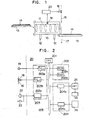
- FIG. 1 is a schematic view showing a drying machine, the temperature of which is controlled in accordance with the present invention.
- the shown drying machine comprises a cylindrical rotor 10 having therefn a steam pipe 11 for supplying steam which serves as a heat source.
- the rotor 10 is driven to rtate by means of driving rollers 12 while itiss-lightly tilted.
- Raw material that is, tobacco leaves, that are conveyed by a conveyor 13, charged into one end of rotor 10 and discharged from the other end into a conveyor 15 after being dried.
- One end of steam pipe 11 is connected to a steam pipe 16 for supplying steam and serving as a heat source and the other end of pipe 11 is connected to a drain pipe 17 so as to allow the rotor 10 to rotate.
- a diaphragm valve 18 is interposed in the steam pipe 16 for starting or stopping the supply of steam.
- the rotor 10 is provided with a temperature detector 19 for detecting the temperature within the rotor 10.
- the valve 18 is controlled to open or close in response to control signal from a control device 20 which is responsive to the temperature signal from the temperature detector 19 so that the temprature inside the rotor 10 is elevated to a preset target temperature and is maintained around that temperature.
- the control device 20 comprises an electronic computer such as microcomputer.
- An electronic computer such as microcomputer.
- Reference 201 in Figure 2 represents a central processor unit (hereinafter referred to as CPU) which is adapted to control the jobs wihich the computer executes in accordance with a program; to control arithmetic processing required during the execution of the jobs and to control other devices and to manage the reception of the data required temperature control.
- CPU central processor unit
- Reference 202 represents a memory comprising a read only memory (hereinafter referred to as ROM) 202a in which programs for predetermined jobs the computer executes are stored and a read/write memory (hereinafter referred to as RAM) 202b in which constants required for the program, operational results and input data are stored.
- ROM read only memory
- RAM read/write memory
- Reference numeral 203 represents a process input/output device which comprises an analog/digital convertor 203a (hereinafter referred to as A/D-C) which converts the temperature signal from the temperature detector 19 into a digital signal suitable for computer processing; a digital/analog convertor 203b (hereinafter referred to D/A-C) which converts the digital data obtained by arithmetic operation in the computer into analog output for driving the diaphragm valve 18; and a digital input device 203c for inputting into a data bus 205 a digital signal for starting the present apparatus in response to a signal generated at a given time by a timer console 22 or a signal generated at a desired time by a manual switch 23.
- A/D-C analog/digital convertor 203a
- D/A-C digital/analog convertor
- Reference numeral 204 represents an input/output device which comprises a serial interface 204a for reception and feeding of data from and to the computer when video information or input data rae displayed on CRT display 24 or printed out by a printer 25 and a keyboard input device 204b for transforming the data from a keyboard 26 operated by an operator when constants and other data are changed and transmitting them to CPU 201.
- the aforementioned control device 20 carries out the temperture control of the drying machine as will be described with reference to the temperature chart shown in Figure 3.
- the temperature is To, and the diaphragm valve 18 is opened at a time to supply steam to the steam pipe 11 as shown in Figure 4 in order to raise the temperature to T R Preset as a target temperature.
- the steam supply causes the temperature of the rotor 10 to elevate.
- the elevation in temperature is etected by the temperature detector 19 and is then inputted into a control device 20.
- the diaphragm is closed as indicated at time t 1 when one of the aforementioned formulae (1) and (2) is satisfied.
- the position on the chart corresponding to the time t 1 is represented as P 1 .
- the temperature of the rotor 10 continues to rise by virtue of the residual heat of the steam even when the valve 18 is closed as mentioned above.
- the control device judges whether G is lower than a preset temperature gradient constant g 2 , that is, and the temperature of the rotor 10 is lower than a temprature T 2 which is a target temperature T R minus temperature coefficient DT 2 , that is,
- the diaphragm valve 18 is opened as indicated at time t 2 when both formulae (3) and (4) are satisfied.
- the position corresponding -to the time t 2 on the chart is represented by P 2 .
- the period of time TA 1 for which steam is supplied after opening the diaphragm 18 is calculated in accordance with the following formula (5) wherein a,B are operation parameters.
- the valve 18 is closed for at least a period of time T B which is preset when writing the program and which takes account of the temperature change which occurs during the period of time TA 1 .
- the valve 18 is, of course, closed when either of the formulae (3) and (4) is satisfied even in the period of time TA 1 .
- the temperature is elevated by the residual heat of supplied steam.
- the valve 18 is held closed when the temperture T 3 of the rotor 10 as indicated at time t 3 (a point P 3 on the chart) falls in a target temperature range, that is, and wherein g 3 is a temperature gradient consant.
- the valve 18 is also held closed as indicated at time t 4 (corresponding to point P 4 on the chart) when the temperature T 4 is higher than the target temperature T R , that is, When the temperature begins to fall due to heat radiation from the rotor 10, the control device judges whether the temperature T 5 is lower than a target temperature TR, that is, and
- valve 18 is opened for supplying steam when both of the formulae (9) and (10) are satisfied.
- the period of steam supply TA 2 is calculated in accordance with the formula (11).
- the valve 18 is closed for at least a time T B .
- the valve is, however, closed immediately when either of the formulae (9) and (10) is not satisfied.
- the temperature of the drying machine is maintained around the target temperature T R by continuing the aforementioned operation.
- Figure 5 is a flow chart of a program for executing the aforementioned control.
- the control device 20 calculates a temperature gradient, that is, change in temperature per unit time G in accordance with the temperature signal from the temperature detector 19 at step S 1 , The control device then judges whether or not the content of a counter I for setting the opening interval of diaphragm valve 18 is equal to or larger than zero at step S 2 . Since the content of the counter is now zero, the program proceeds to step 3 at which the controls device judges. whether or not the content of a counter II for setting the closed interval of the diaphragm valve 18 is larger than zero. Since nothing is stored in the counter II, program proceeds to step S4 at which the control device judges whether or not the temperature T represented by the temperature signal from the temperature detector 18 is lower than the target temperature.
- step S 5 Since temperature T is, of course, lower than TR at this time, program proceeds to step S 5 .
- the control device judges whether or not the control state is state 3.
- the control state used herein means a state which is incremented from 1 to 3 depending on the progress in control.
- the control state is now state 1 since the program has just started. Then the program proceeds to step S6 at which judgement is carried out whether or not the control state is state 1. Since the answer is yet at this time, program proceeds to step S 7 .
- step S7 judgement is carried out whether or not the value G obtained at step S 1 is equal to or larger than a preset temperature gradient constant g1. If the result of judgement is no, program proceeds to step S 8 at which the judgement is carried out whether or not the detected temperature is equal to or larger than the temperature To at the start of control plus the preset temperature DT 1 . Since the result of judgement is, of course, no, the program proceeds to next step S9 at which the opening of the diaphragm valve 18 is set to maximum to supply steam. After the steam begins to be supplied program returns to step S 1 again to calculate G upon the basis of the detected temperature signal.
- step S 4 Program goes to step S 4 via steps S2 and S3 since the counters I are to found to be not set at the aforementioned steps. If T ⁇ T R , the program goes to step S5. Since the control state is still found to be state 1 at the aforementioned step, the program proceeds to step S 7 via step S6 ⁇ Program goes to step S 10 to set the control state 2 when G which is calculated at step S 1 is equal to or larger than g 1 or the temperature T is equal to or larger than T O + DT 1 due to elevation in temperature by steam supply.
- step S 11 the opening of the diaphragm valve 18 is set to zero, that is, the valve is closed and zero is set in the counter I and time T B is set in counter II. Program returns to step S 1 after step S 11 .
- step S 3 As a result of setting of T B in the counter II at the step S 11 the judgement at step S 3 is yes.
- Program goes to step S 12 at which the counter II is decremented and the opening of the diaphragm valve 18 is set to a minimum value. The valve may be closed at the minimum value.
- step S 12 After completion of the step S 12 , program returns to step S 1 and goes to step S 6 via steps S 2 , S 3 , S 4 and S 5 .
- Program goes to step S 13 since judgement is no at step S 6 .
- step S 13 judgement whether or not the detected temperature is lower than the target temperature TR minus preset temperature DT2 is carried out. If the judgement result is yes, the judgement whether or not G is equal to or larger than a preset value g 2 is carried out at next step S 14 . If the judgement result is yes, judgement whether or not the content of the counter I is equal to or lower than zero is carried out at step S 15 . The judgement result is yes.
- program returns to step S 1 again and then returns to step S 15 via steps S 2 , S 4 , S 5 , S 6 , S 13 and S 14 . Since the judgement at step S 15 is no, program I is decremented and the opening of the diaphragm valve 18 is set to a maximum value.
- step S 17 After completion.of the steps S 17 , program returns to step S 1 and loops through the steps S 1 , S 2 , S4 to S 6 , S 13 to S 15 , S 17 until the content of the counter I becomes zero.
- judgement at steps S 2 is yes and program does not go to step S 4 , but to step S 3 .
- judgement at step S 3 is yes, program proceeds to step S 12 at which the counter II is decremented and the opening of the valve 18 is set to a minium, that is, closed. Program then returns to step 5 1' The program then loops through steps S 1 to S 3 and S 12 until the content of the counter II becomes zero.
- step S 18 at which the opening of the diaphragm valve 18 is set to minimum, that is, closed and the counter I is reset to zero.
- step S 12 at which the decrement of the counter II begins and the valve opening is set to minimum, that is, closed. Operation via step S 12 is continued until the period of time TB stored in counter II has passed.
- step S 18 operation is carried out via steps S 2 to S 6 or S 1 4 or S 14 , S 18 .
- Judgement at step S 4 is no when the temperature T becomes higher than T R by the residual heat of the steam. As a result of this the program goes to step S 19 .
- Control state is set to state 3 at step S 19 .
- Program then proceeds to step S 20 at which judgement whether or not T is lower than T R is carried out. If the result of judgement is no, program proceeds to step S 21 at which the opening of the diaphragm valve 18 is set to minimum, that is, closed and the counter I is set to zer. The content of the step S 21 is similar to that of step S 18 . Following the step S 21 , program returns to step S 1 and goes to step S 4 via S 2 and S 3 . If the judgement result is yes, program proceeds to step S 5 . Since the judgement at step S 5 is yes, program proceeds to step S 20 via step S 19 .
- step S 20 Since the judgement at step S 20 is also yes, the program proceeds to step S 22 at which judgement whether or not G is equal to or lwer than a preset negative temperature gradient constant g 3 . If the judgement result is no, program proceeds to step S 21 . If yes, it proceeds to step S 15 .
- step S 15 judgement whether or not the content of the counter I is equal to or lower than zero is carried out at this step S 15 . Since the judgement result is yes, program proceeds to step S 16 at which the opening time interval TA 1 of the diaphragm valve 18 and valve closing interval T B are stored in counters I and II respectively. Then program returns to step S 1 and goes to step S 17 via steps S 2 , S 4 , S 5 , S 19 , S 20 , S 22 and S 15 . At step S 17 the counter I is decremented and the diaphragm valve 18 is fully opened. Following the step S 17 , program returns to step S 1 . Control is then carried out via one of steps S 12 , 5 16 , S 17 and S 21 to close or open the valve such that the temperature T is maintained around the target temperature T R .
- the temperature of the drying machine can be maintained in the vicinity of the target temperature in a simple manner. Presetting of a temperature required for controlling the moisture content of raw material such as tobacco leaves can readily be realized. Practically very useful effects can be provided.
Landscapes
- Engineering & Computer Science (AREA)
- Mechanical Engineering (AREA)
- General Engineering & Computer Science (AREA)
- Life Sciences & Earth Sciences (AREA)
- Microbiology (AREA)
- Drying Of Solid Materials (AREA)
Applications Claiming Priority (2)
| Application Number | Priority Date | Filing Date | Title |
|---|---|---|---|
| JP195335/83 | 1983-10-20 | ||
| JP58195335A JPS6089677A (ja) | 1983-10-20 | 1983-10-20 | 乾燥機の温度制御方法 |
Publications (3)
| Publication Number | Publication Date |
|---|---|
| EP0139536A2 true EP0139536A2 (fr) | 1985-05-02 |
| EP0139536A3 EP0139536A3 (en) | 1986-02-12 |
| EP0139536B1 EP0139536B1 (fr) | 1988-05-18 |
Family
ID=16339458
Family Applications (1)
| Application Number | Title | Priority Date | Filing Date |
|---|---|---|---|
| EP84307242A Expired EP0139536B1 (fr) | 1983-10-20 | 1984-10-19 | Procédé et dispositif pour régler la température d'une machine à sécher |
Country Status (4)
| Country | Link |
|---|---|
| US (1) | US4587743A (fr) |
| EP (1) | EP0139536B1 (fr) |
| JP (1) | JPS6089677A (fr) |
| DE (1) | DE3471366D1 (fr) |
Cited By (5)
| Publication number | Priority date | Publication date | Assignee | Title |
|---|---|---|---|---|
| US5258162A (en) * | 1989-11-07 | 1993-11-02 | Tetra Alfa Holdings S.A. | Method of producing a gaseous hydrogen peroxide-containing sterilization fluid |
| WO1994015490A1 (fr) * | 1993-01-08 | 1994-07-21 | Alternative Pioneering Systems, Inc. | Systeme de commande de deshydrateur d'aliments |
| CN106418632A (zh) * | 2016-11-23 | 2017-02-22 | 上海烟草集团有限责任公司 | 一种电子设备、及其应用的温度控制方法及系统 |
| CN108645200A (zh) * | 2018-05-29 | 2018-10-12 | 大连维钛克科技股份有限公司 | 烘干槽烘干控制系统 |
| CN113040411A (zh) * | 2021-03-12 | 2021-06-29 | 浙江中烟工业有限责任公司 | 一种参数自优化的烟机蒸汽加热控制模型及其构建方法 |
Families Citing this family (8)
| Publication number | Priority date | Publication date | Assignee | Title |
|---|---|---|---|---|
| JPS6314076A (ja) * | 1986-07-01 | 1988-01-21 | 三井造船株式会社 | 回転式乾燥機の運転方法 |
| ES2069483B1 (es) * | 1993-07-05 | 1998-05-16 | Invest De La Ind Agroalimentar | Secadero automatizado de hortalizas y similares. |
| US6183186B1 (en) | 1997-08-29 | 2001-02-06 | Daitron, Inc. | Wafer handling system and method |
| DE10360485B4 (de) * | 2003-12-22 | 2005-11-24 | Airbus Deutschland Gmbh | Verfahren und Vorrichtung zur Temperaturüberwachung entlang einer Messleitung |
| KR100664289B1 (ko) * | 2006-03-14 | 2007-01-04 | 엘지전자 주식회사 | 의류 건조기의 건조 방법 |
| CN103383182A (zh) * | 2012-11-23 | 2013-11-06 | 无锡众望四维科技有限公司 | 热风循环烘箱的温度控制装置及方法 |
| CN114545995B (zh) * | 2022-03-10 | 2023-05-16 | 安徽中烟工业有限责任公司 | 一种松散回潮回风温度的控制方法 |
| CN118605653B (zh) * | 2024-08-07 | 2024-10-22 | 中京新材料(常州)有限公司 | 一种隧道烘箱加热段抗扰动的精确温度控制方法 |
Family Cites Families (7)
| Publication number | Priority date | Publication date | Assignee | Title |
|---|---|---|---|---|
| DE817866C (de) * | 1950-04-16 | 1951-10-22 | Otto Dipl Oec Kiefer | Temperaturregelung bei Trocknern mit ueberhitztem Dampf als Trockenmittel |
| US3013785A (en) * | 1958-03-24 | 1961-12-19 | Phillips Petroleum Co | Dryer temperature controls |
| DE1181637B (de) * | 1963-01-08 | 1964-11-12 | Siemens Ag | Regelanlage fuer einen Gleichstromtrockner mit rotierender Trommel |
| US3840025A (en) * | 1972-08-14 | 1974-10-08 | Industrial Nucleonics Corp | Tobacco moisture control system and method |
| US3905123A (en) * | 1973-10-15 | 1975-09-16 | Industrial Nucleonics Corp | Method and apparatus for controlling a tobacco dryer |
| US4140274A (en) * | 1977-05-11 | 1979-02-20 | Nabinger Herman G | Control device for a warm air furnace |
| US4409662A (en) * | 1980-12-29 | 1983-10-11 | Halliburton Company | Programmable digital temperature controller |
-
1983
- 1983-10-20 JP JP58195335A patent/JPS6089677A/ja active Granted
-
1984
- 1984-10-18 US US06/662,079 patent/US4587743A/en not_active Expired - Lifetime
- 1984-10-19 DE DE8484307242T patent/DE3471366D1/de not_active Expired
- 1984-10-19 EP EP84307242A patent/EP0139536B1/fr not_active Expired
Cited By (5)
| Publication number | Priority date | Publication date | Assignee | Title |
|---|---|---|---|---|
| US5258162A (en) * | 1989-11-07 | 1993-11-02 | Tetra Alfa Holdings S.A. | Method of producing a gaseous hydrogen peroxide-containing sterilization fluid |
| WO1994015490A1 (fr) * | 1993-01-08 | 1994-07-21 | Alternative Pioneering Systems, Inc. | Systeme de commande de deshydrateur d'aliments |
| CN106418632A (zh) * | 2016-11-23 | 2017-02-22 | 上海烟草集团有限责任公司 | 一种电子设备、及其应用的温度控制方法及系统 |
| CN108645200A (zh) * | 2018-05-29 | 2018-10-12 | 大连维钛克科技股份有限公司 | 烘干槽烘干控制系统 |
| CN113040411A (zh) * | 2021-03-12 | 2021-06-29 | 浙江中烟工业有限责任公司 | 一种参数自优化的烟机蒸汽加热控制模型及其构建方法 |
Also Published As
| Publication number | Publication date |
|---|---|
| DE3471366D1 (en) | 1988-06-23 |
| EP0139536A3 (en) | 1986-02-12 |
| JPS6319791B2 (fr) | 1988-04-25 |
| JPS6089677A (ja) | 1985-05-20 |
| EP0139536B1 (fr) | 1988-05-18 |
| US4587743A (en) | 1986-05-13 |
Similar Documents
| Publication | Publication Date | Title |
|---|---|---|
| EP0139536A2 (fr) | Procédé et dispositif pour régler la température d'une machine à sécher | |
| US4430698A (en) | Three-mode process control | |
| EP0284635A1 (fr) | Système de commande pour appareil de cuisson | |
| CA2217381A1 (fr) | Procede de reaction pour commander des processus non lineaires | |
| CA2138114A1 (fr) | Methode et dispositif pour reduire les depassements par rapport au point de consigne dans un systeme de conditionnement d'air | |
| EP0482900A2 (fr) | Régulateur adaptatif dans un système de commande de processus et procédé à cet effet | |
| DE69523874T2 (de) | Heizzeit-Kontrollvorrichtung und Verwendung dieser in einem Mikrowellenofen | |
| JPH0425004B2 (fr) | ||
| US4730101A (en) | Apparatus and method for controlling the temperature of a furnace | |
| DE3475100D1 (en) | Defrost control method and device for heat pumps | |
| US4796207A (en) | Process and apparatus for roasting with a roasting vessel | |
| SE506605C2 (sv) | Förfarande för styrd kokning i en mikrovågsugn, sådan ugn och dess användning | |
| EP0146826B1 (fr) | Procédé de la régulation de la température d'un appareil de séchage | |
| US6861018B2 (en) | Temperature control method and apparatus for injection molding structure | |
| SE514526C2 (sv) | Förfarande för styrning av ett kokningsförlopp i en mikrovågsugn samt mikrovågsugn härför | |
| EP0209201B1 (fr) | Procédé pour chauffer dans un four et four à micro-ondes appliquant le procédé | |
| JP3269174B2 (ja) | 水分または揮発分計 | |
| SU966248A1 (ru) | Устройство дл управлени мощностью турбины | |
| SU1174909A1 (ru) | Устройство дл регулировани двух св занных параметров | |
| SU929654A1 (ru) | Устройство дл автоматического регулировани температурного режима переэтерификатора | |
| JPS642857B2 (fr) | ||
| JPS57111617A (en) | Temperature controller | |
| JPS5692957A (en) | Control apparatus in asphalt plant | |
| SU1142713A1 (ru) | Способ автоматического управлени процессом сушки | |
| SU907062A1 (ru) | Способ автоматического управлени процессом разваривани крахмалсодержащего сырь |
Legal Events
| Date | Code | Title | Description |
|---|---|---|---|
| PUAI | Public reference made under article 153(3) epc to a published international application that has entered the european phase |
Free format text: ORIGINAL CODE: 0009012 |
|
| AK | Designated contracting states |
Designated state(s): DE GB IT |
|
| PUAL | Search report despatched |
Free format text: ORIGINAL CODE: 0009013 |
|
| AK | Designated contracting states |
Designated state(s): DE GB IT |
|
| 17P | Request for examination filed |
Effective date: 19851220 |
|
| RAP1 | Party data changed (applicant data changed or rights of an application transferred) |
Owner name: JAPAN TOBACCO INC. |
|
| 17Q | First examination report despatched |
Effective date: 19861003 |
|
| GRAA | (expected) grant |
Free format text: ORIGINAL CODE: 0009210 |
|
| AK | Designated contracting states |
Kind code of ref document: B1 Designated state(s): DE GB IT |
|
| REF | Corresponds to: |
Ref document number: 3471366 Country of ref document: DE Date of ref document: 19880623 |
|
| ITF | It: translation for a ep patent filed | ||
| PLBE | No opposition filed within time limit |
Free format text: ORIGINAL CODE: 0009261 |
|
| STAA | Information on the status of an ep patent application or granted ep patent |
Free format text: STATUS: NO OPPOSITION FILED WITHIN TIME LIMIT |
|
| 26N | No opposition filed | ||
| ITTA | It: last paid annual fee | ||
| PGFP | Annual fee paid to national office [announced via postgrant information from national office to epo] |
Ref country code: DE Payment date: 20001009 Year of fee payment: 17 |
|
| PGFP | Annual fee paid to national office [announced via postgrant information from national office to epo] |
Ref country code: GB Payment date: 20001018 Year of fee payment: 17 |
|
| PG25 | Lapsed in a contracting state [announced via postgrant information from national office to epo] |
Ref country code: GB Free format text: LAPSE BECAUSE OF NON-PAYMENT OF DUE FEES Effective date: 20011019 |
|
| REG | Reference to a national code |
Ref country code: GB Ref legal event code: IF02 |
|
| GBPC | Gb: european patent ceased through non-payment of renewal fee |
Effective date: 20011019 |
|
| PG25 | Lapsed in a contracting state [announced via postgrant information from national office to epo] |
Ref country code: DE Free format text: LAPSE BECAUSE OF NON-PAYMENT OF DUE FEES Effective date: 20020702 |