EP0139573A2 - Verfahren und Kristallisationsanlage mit niveaueinstellbarer axialer Rückführung - Google Patents
Verfahren und Kristallisationsanlage mit niveaueinstellbarer axialer Rückführung Download PDFInfo
- Publication number
- EP0139573A2 EP0139573A2 EP84401940A EP84401940A EP0139573A2 EP 0139573 A2 EP0139573 A2 EP 0139573A2 EP 84401940 A EP84401940 A EP 84401940A EP 84401940 A EP84401940 A EP 84401940A EP 0139573 A2 EP0139573 A2 EP 0139573A2
- Authority
- EP
- European Patent Office
- Prior art keywords
- crystallizer
- solution
- crystallization
- free surface
- crystals
- Prior art date
- Legal status (The legal status is an assumption and is not a legal conclusion. Google has not performed a legal analysis and makes no representation as to the accuracy of the status listed.)
- Granted
Links
- 238000002425 crystallisation Methods 0.000 title claims abstract description 29
- 238000000034 method Methods 0.000 title claims abstract description 17
- 238000004064 recycling Methods 0.000 title claims description 22
- 239000013078 crystal Substances 0.000 claims abstract description 36
- 230000008025 crystallization Effects 0.000 claims abstract description 27
- 238000001704 evaporation Methods 0.000 claims abstract description 6
- 230000008020 evaporation Effects 0.000 claims abstract description 6
- 239000004606 Fillers/Extenders Substances 0.000 claims description 8
- 238000000926 separation method Methods 0.000 claims description 8
- 238000003303 reheating Methods 0.000 claims description 6
- 238000010079 rubber tapping Methods 0.000 claims description 5
- 230000000295 complement effect Effects 0.000 claims description 4
- 238000011144 upstream manufacturing Methods 0.000 claims description 3
- 238000009835 boiling Methods 0.000 claims description 2
- 238000010908 decantation Methods 0.000 claims 1
- 238000010438 heat treatment Methods 0.000 abstract description 3
- 239000007788 liquid Substances 0.000 description 10
- 230000015572 biosynthetic process Effects 0.000 description 5
- 238000009434 installation Methods 0.000 description 4
- 230000014759 maintenance of location Effects 0.000 description 4
- 230000004048 modification Effects 0.000 description 3
- 238000012986 modification Methods 0.000 description 3
- 238000005265 energy consumption Methods 0.000 description 2
- 238000001914 filtration Methods 0.000 description 2
- 238000011084 recovery Methods 0.000 description 2
- 230000002411 adverse Effects 0.000 description 1
- 238000005119 centrifugation Methods 0.000 description 1
- 238000010276 construction Methods 0.000 description 1
- 238000007599 discharging Methods 0.000 description 1
- 235000021183 entrée Nutrition 0.000 description 1
- 239000012530 fluid Substances 0.000 description 1
- 238000010899 nucleation Methods 0.000 description 1
- 210000000056 organ Anatomy 0.000 description 1
- 230000001737 promoting effect Effects 0.000 description 1
- 238000009834 vaporization Methods 0.000 description 1
- 230000008016 vaporization Effects 0.000 description 1
- 238000005406 washing Methods 0.000 description 1
Images

Classifications
-
- B—PERFORMING OPERATIONS; TRANSPORTING
- B01—PHYSICAL OR CHEMICAL PROCESSES OR APPARATUS IN GENERAL
- B01D—SEPARATION
- B01D9/00—Crystallisation
- B01D9/0018—Evaporation of components of the mixture to be separated
- B01D9/0022—Evaporation of components of the mixture to be separated by reducing pressure
-
- B—PERFORMING OPERATIONS; TRANSPORTING
- B01—PHYSICAL OR CHEMICAL PROCESSES OR APPARATUS IN GENERAL
- B01D—SEPARATION
- B01D9/00—Crystallisation
- B01D9/0018—Evaporation of components of the mixture to be separated
- B01D9/0031—Evaporation of components of the mixture to be separated by heating
-
- B—PERFORMING OPERATIONS; TRANSPORTING
- B01—PHYSICAL OR CHEMICAL PROCESSES OR APPARATUS IN GENERAL
- B01D—SEPARATION
- B01D9/00—Crystallisation
- B01D9/0036—Crystallisation on to a bed of product crystals; Seeding
Definitions
- the present invention relates to a method and a device for crystallization of a crystallizable solution of a soluble product, in particular of a water-soluble product, which are capable of having multiple applications within industrial installations or pilot installations.
- a well-known crystallization process currently implemented in crystallizers of the conventional type, used in industrial or pilot plants, consists in introducing, into a crystallizer of vertical axis, a certain volume of a solution to be crystallized brought to a temperature close to its evaporation temperature for the reduced pressure established in the crystallizer; maintaining said reduced pressure above the free surface of the solution to be crystallized in the crystallizer, so as to promote the formation of vapor above the free surface of the solution and the formation of crystals in the solution; continuously recycling the solution to be crystallized, leaving it at the bottom of the crystallizer, then heating it in a heat exchanger, in which the solution is in heat exchange condition with steam collected at the top of the crystallizer and recompressed, and finally reintroducing the warmed solution into the crystallizer, slightly below the level of the free surface of the solution in the crystallizer; and removing, in the lower part of the crystallizer, the crystals formed by separating them by filtration from the solution.
- This known method therefore consists in promoting the continuous development of a phenomenon commonly designated by the terms “surface flash of evaporation”, by which the evaporation of the liquid above the free surface of the volume of solution present in the crystallizer is accompanied by the formation of crystals of the product dissolved in the solution, and a drop in the temperature of the solution.
- This drop temperature must be compensated for the process to continue, and this thermal compensation is ensured by continuous recirculation and heating of the solution to be crystallized by taking the necessary amount of heat from the vapor collected above the free surface of the volume of solution present in the crystallizer, after mechanical recompression of this vapor.
- the size of the crystals that can be obtained in such a device is related to the retention time of the crystals in the crystallizer.
- the heat exchanger in the exchanger is no longer sufficient to provide suitable compensation, since the temperature difference between the two fluids of the exchanger is reduced; the mass of solution present in the crystallizer is therefore no longer maintained at a sufficient temperature. It therefore becomes essential to increase the mechanical recompression of the vapor, in order to increase the temperature of the latter at the inlet of the exchanger. But this can only be obtained at the cost of very high energy consumption.
- the object of the invention is to remedy this major drawback, by preventing the re-flow of the crystallizer in recycled and heated solution from passing directly from the outlet to the inlet of the recycling pipe and by ensuring that it is always favorably distributed throughout the liquid mass present in the crystallizer.
- Another object of the invention is to allow, in a crystallizer of given construction, to seek the optimal efficiency, that is to say, the best crystallization yield, without this resulting in an impact on the heat exchanges in the reheating exchanger, and consequently without causing any modification to the mechanical recompression of the vapor which feeds the heat exchanger.
- the invention finally aims to allow easy adjustment of the operating conditions of an industrial installation or a quick and simple modification of a pilot installation.
- the subject of the invention is a process of the type presented above, which is characterized by the fact that it also consists in ensuring a substantially vertical reintroduction of the recycled solution into the volume of solution contained. in the crystallizer, and to maintain this reintroduction slightly below the free surface of the solution in the crystallizer, whatever the level of this free surface in the crystallizer.
- Such a vertical recharge maintained slightly below the free surface of the solution in the crystallizer ensures at the same time an excellent distribution of the solution reheated and reintroduced into the crystallizer, through the entire volume of solution present in the latter, and a retention time which can be modified at will, without any unfavorable consequence on the energy consumption linked to the recompression of the vapor.
- the recovery of the crystals can be ensured by a stitching on the recycled solution, at the outlet in the lower part of the crystallizer, and the solution separated from the crystals being re-injected into the recycled solution, before its passage through the 'heat exchanger.
- the separation of the crystals can be done by any suitable means, for example, by filtration or centrifugation.
- the method also consists in collecting and decanting the crystals, in the lower part of the crystallizer, in a crystallization leg, in recovering the crystals by a stitching on the crystallization leg, between the two ends of the latter, and to reinject the separated solution of the crystals into the lower end of the crystallization leg, in order to create a slight counter-current which causes the crystals which are too fine to rise in the crystallizer.
- the invention also relates to a device of the type presented above and arranged for the implementation of the method according to the invention, this device being characterized by the fact that the outlet of the recycling pipe is delimited by a nozzle, which is arranged in the crystallizer and opens upwards into the latter, the device also comprising at least one leveling extension, intended to be connected, if necessary, to the nozzle so that the recycled solution is reintroduced into the volume of solution present in the crystallizer slightly below the level of the free surface of this volume of solution in the crystallizer.
- the end of the recycling line is arranged along the axis of the crystallizer.
- the device may comprise several axial extenders, possibly identical to each other, and intended to be mounted end to end on the end piece, depending on the level of the free surface of the solution in the crystallizer; advantageously, in order to facilitate the leveling operations, the endpiece carries complementary fastening means of fastening means carried by each axial extension; advantageously, in order to allow stacking of the extenders, each of them also carries complementary attachment means of attachment means carried by at least one other axial extension.
- the stitching line and the reinjection line which are associated with the seeding member. p a ration of the crystals, can connect said member to the recycle line, between the crystallizer and the heat exchanger, the tapping conduit opening into the then upstream recycle line from the point where the pipe opens reinjection into this pipe.
- the device further comprises a crystallization leg, which extends axially under the crystallizer and opens into the latter by its upper end, the tapping pipe connecting the separation member to the crystallization leg and opening into the central part thereof, while the reinjection pipe connects said member to the lower end of the crystallization leg, into which it opens axially in order to create a counter-current for washing the crystals collected in the leg and returning excessively fine crystals to the crystallizer.
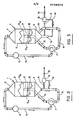
- the known crystallization device shown in FIG. 1 comprises a crystallizer 1, consisting of a central cylindrical part 2 of circular section, as well as a lower part 3 and an upper part 4, which are each frustoconical and connected to the central part 2 by their large base.
- the upper part 4 is connected to the inlet of a steam pipe 5, on which is mounted a mechanical vapor recompression pump 6, the outlet of which opens into a heat exchanger 7.
- the lower part 3 is connected to the inlet of a recycling pipe 8, which is connected to the heat exchanger 7 and extends, beyond the latter, until it opens, via its outlet 9, tangentially in the central part 2 of the crystallizer 1, perpendicular to the axis vertical of the latter, and just below the level of the free surface 10 (indicated in dotted lines) of a mass of solution to be crystallized which is contained in the crystallizer 1.
- This solution is at a temperature close to its vaporization temperature for the pressure in the crystallizer.
- the pump 6, by sucking up the vapor which forms in the crystallizer 1, above the free surface 10, constitutes a device for placing under vacuum, which promotes the formation of vapor, by the phenomenon known as "flash of evaporation of surface".
- This vapor recompressed by the pump 6, is then brought in the heat exchange condition in the exchanger 7, with the solution which is taken up at the lower end of the crystallizer 1 by the pipe 8, so that this solution is reheated in the exchanger 7 is then reintroduced into the crystallizer 1, in order to compensate for the drop in temperature of the liquid mass contained in the crystallizer 1, due to the formation of vapor.
- such a device has the disadvantage that the level of the free surface 10 cannot be raised in the crystallizer 1 without causing a considerable increase in the energy consumed by the assembly.
- the device according to the invention and shown in Figure 2 is identical to the device of Figure 1, except as regards the return of the recycling line 8 in the crystallizer 1.
- the recycling line 8 consists, downstream of the heat exchanger 7, by a re-supply section 15 which passes through the frustoconical wall of the lower part 3 of the crystallizer 1 and which ends in a nozzle 16 directed axially upward and opening out, at its end upper, just below the minimum level 10 m from the free surface of the liquid mass contained in the crystallizer 1, so that the solution reintroduced into the latter is distributed suitably throughout this liquid mass.
- an axial extension 17 is attached to the upper end of the endpiece 16, the upper end of which opens just below the new level of the free surface 10 M , in order to maintain the advantage of the good distribution of the recycled solution in the liquid mass of the crystallizer 1, and to obtain, in addition, an increase in the retention time, which corresponds to an increase in the size of the crystals, without disturbing the heat exchanges in the exchanger 7 and therefore without disturbing the operation of the pump 6.
- one or more extenders such as 17 can be mounted end to end on the end piece 16.
- the extenders 17 are identical to each other and each have at their ex-5 lower end means of quick fastening at the end upper end of the endpiece 16 or at the upper end of an extension 17 already mounted on this endpiece 16.
- the device shown in FIG. 3 is identical to that of FIG. 2, except as regards the position of the inlet of the recycling pipe 8 and the recovery of the crystals.
- the recycling pipe 8 consists, upstream of the heat exchanger 7, of a return section 18, which is connected by its inlet to the frustoconical wall of the lower part 3 of the crystallizer 1.
- this lower part 3 is connected to the upper end of an axial crystallization leg 19; the leg 19 has a cylindrical central part and ends in a converging frustoconical lower end.
- the transplanting line 11 connects the filter 12 to the leg 19, into which it opens at the central part of the latter; the reinjection pipe also connects the filter 12 to the leg 19, but by opening axially in the lower end of the latter, so as to create a counter-current by the reinjection of the solution recovered in the filter 12; the counter-current washes the crystals collected in the leg 19 and causes the finest crystals to rise in the crystallizer 1, while the larger crystals are taken to the filter 12 and then evacuated via line 13.
Landscapes
- Chemical & Material Sciences (AREA)
- Crystallography & Structural Chemistry (AREA)
- Chemical Kinetics & Catalysis (AREA)
- Physics & Mathematics (AREA)
- Thermal Sciences (AREA)
- Organic Low-Molecular-Weight Compounds And Preparation Thereof (AREA)
Applications Claiming Priority (2)
| Application Number | Priority Date | Filing Date | Title |
|---|---|---|---|
| FR8315427 | 1983-09-28 | ||
| FR8315427A FR2552340B1 (fr) | 1983-09-28 | 1983-09-28 | Procede et dispositif de cristallisation a recyclage axial de niveau reglable |
Publications (3)
| Publication Number | Publication Date |
|---|---|
| EP0139573A2 true EP0139573A2 (de) | 1985-05-02 |
| EP0139573A3 EP0139573A3 (en) | 1985-06-19 |
| EP0139573B1 EP0139573B1 (de) | 1987-05-06 |
Family
ID=9292621
Family Applications (1)
| Application Number | Title | Priority Date | Filing Date |
|---|---|---|---|
| EP84401940A Expired EP0139573B1 (de) | 1983-09-28 | 1984-09-27 | Verfahren und Kristallisationsanlage mit niveaueinstellbarer axialer Rückführung |
Country Status (3)
| Country | Link |
|---|---|
| EP (1) | EP0139573B1 (de) |
| DE (1) | DE3463448D1 (de) |
| FR (1) | FR2552340B1 (de) |
Cited By (3)
| Publication number | Priority date | Publication date | Assignee | Title |
|---|---|---|---|---|
| EP0646399A1 (de) * | 1992-05-07 | 1995-04-05 | Tsukishima Kikai Co. Ltd. | Verfahren zur Kristallisierung von einer Schmelze mit adiabatischer Kühlung und Vorrichtung dafür |
| EP0945158A1 (de) * | 1998-03-23 | 1999-09-29 | Ajinomoto Co., Inc. | Kristallisationsverfahren mit einstellbarer Partikelgrössenverteilung |
| FR2922890A1 (fr) * | 2007-10-30 | 2009-05-01 | Roquette Freres | Procede d'evapocristallisation du maltitol. |
Family Cites Families (6)
| Publication number | Priority date | Publication date | Assignee | Title |
|---|---|---|---|---|
| FR352846A (fr) * | 1905-03-29 | 1905-08-22 | Henry Roy | évaporation et cuite des sirops sucrés sous faible épaisseur |
| US2384747A (en) * | 1942-05-13 | 1945-09-11 | Zaremba Company | Crystallizing evaporator |
| US2555340A (en) * | 1945-06-18 | 1951-06-05 | Int Salt Co | Method and apparatus for refining salt or other soluble substances |
| FR1067269A (fr) * | 1952-11-28 | 1954-06-14 | Perfectionnements aux procédés de purification de sels et notamment du sel marin | |
| FR1583698A (de) * | 1968-02-20 | 1969-11-28 | ||
| DE3029541C2 (de) * | 1980-08-04 | 1983-12-29 | Helmut 4690 Herne Apfelbaum | Verfahren und Vorrichtung zur Reinigung von Abwasser |
-
1983
- 1983-09-28 FR FR8315427A patent/FR2552340B1/fr not_active Expired
-
1984
- 1984-09-27 DE DE8484401940T patent/DE3463448D1/de not_active Expired
- 1984-09-27 EP EP84401940A patent/EP0139573B1/de not_active Expired
Cited By (7)
| Publication number | Priority date | Publication date | Assignee | Title |
|---|---|---|---|---|
| EP0646399A1 (de) * | 1992-05-07 | 1995-04-05 | Tsukishima Kikai Co. Ltd. | Verfahren zur Kristallisierung von einer Schmelze mit adiabatischer Kühlung und Vorrichtung dafür |
| EP0945158A1 (de) * | 1998-03-23 | 1999-09-29 | Ajinomoto Co., Inc. | Kristallisationsverfahren mit einstellbarer Partikelgrössenverteilung |
| US6364914B1 (en) | 1998-03-23 | 2002-04-02 | Ajinomoto Co., Inc. | Method of crystallization with the particle size distribution being controlled |
| KR100554858B1 (ko) * | 1998-03-23 | 2006-02-24 | 아지노모토 가부시키가이샤 | 입도 분포 제어 결정 석출법 |
| FR2922890A1 (fr) * | 2007-10-30 | 2009-05-01 | Roquette Freres | Procede d'evapocristallisation du maltitol. |
| EP2055197A1 (de) | 2007-10-30 | 2009-05-06 | Roquette Freres | Verfahren zum Verdampfen und Kristallisieren von Maltitol |
| US8012263B2 (en) | 2007-10-30 | 2011-09-06 | Roquette Freres | Process for the evapocrystallization of maltitol |
Also Published As
| Publication number | Publication date |
|---|---|
| FR2552340B1 (fr) | 1988-02-19 |
| DE3463448D1 (en) | 1987-06-11 |
| EP0139573B1 (de) | 1987-05-06 |
| EP0139573A3 (en) | 1985-06-19 |
| FR2552340A1 (fr) | 1985-03-29 |
Similar Documents
| Publication | Publication Date | Title |
|---|---|---|
| FR2773793A1 (fr) | Procede et systeme pour separer un glycol de courants de glycol/saumure | |
| WO2010020723A9 (fr) | Procede de dessalement ou d'epuration d'eau par distillation d'un spray (pompe a spray : pas). | |
| EP0000110B1 (de) | Verfahren zur Herstellung von Acrylsäure aus deren Lösungen in Tri-n-butylphosphat | |
| EP2507168B1 (de) | Verfahren zur herstellung von phosphorsäure | |
| EP0139573B1 (de) | Verfahren und Kristallisationsanlage mit niveaueinstellbarer axialer Rückführung | |
| WO2017042072A1 (fr) | Procédé de purification d'un flux de gaz chargé en cov | |
| CA1146339A (fr) | Procede et dispositif de traitement physique et chimique d'un courant gazeux | |
| EP0296064B1 (de) | Wasserreinigungsbehälter mit einem Dampferzeuger | |
| FR2501520A1 (fr) | Procede pour le transfert de constituants entre un courant de liquide et un courant de vapeur circulant en sens contraire, et installation separatrice pour la mise en oeuvre de ce procede | |
| FR2550325A1 (fr) | Procede et installation de distillation d'air au moyen d'une double colonne | |
| FR2495185A1 (fr) | Procede et dispositif pour refroidir les gaz de hauts fourneaux | |
| CA2692519C (fr) | Appareil de cristallisation a circulation forcee | |
| CN104524806B (zh) | 一种乌洛托品完全连续结晶生产工艺及设备 | |
| EP0015626B1 (de) | Verfahren und Vorrichtung zur Herstellung von Natriumbikarbonatkristallen | |
| EP4433427A1 (de) | Verfahren und vorrichtung zur wasserentsalzung | |
| CN205796568U (zh) | 一种浓缩蒸发分离器 | |
| EP0237685A1 (de) | Vorrichtung zur Desorption von Aktivkohle | |
| FR2531419A1 (fr) | Procede de pompage et de distillation utilisant l'energie solaire | |
| FR2582015A1 (fr) | Procede et installation de preparation de dextrose cristallise anhydre | |
| FR2597115A1 (fr) | Procede et installation pour la production en continu de cristaux de sucre a partir de sirops | |
| CN220811937U (zh) | 一种废水闪蒸罐 | |
| EP0402190A1 (de) | Verfahren zur Verbesserung der Extraktionsrate von Zucker aus einem Sirup der Kochmasse C durch Verminderung der Temperatur des Endes der Kristallisation | |
| LU82924A1 (fr) | Procede de prediffusion en sucrerie | |
| EP0094874A1 (de) | Flüssigkeits-Dampf-Trennungsvorrichtung mit gleichzeitiger Extraktion der getrennten Flüssigkeit und der Flüssigkeit irgendwo in einer Anlage vorhanden | |
| WO2025017093A1 (fr) | Refroidisseur de produit(s) issu(s) d'un réacteur thermochimique, installation de liquéfaction ou de carbonisation hydrothermale intégrant un tel refroidisseur |
Legal Events
| Date | Code | Title | Description |
|---|---|---|---|
| PUAI | Public reference made under article 153(3) epc to a published international application that has entered the european phase |
Free format text: ORIGINAL CODE: 0009012 |
|
| PUAL | Search report despatched |
Free format text: ORIGINAL CODE: 0009013 |
|
| 17P | Request for examination filed |
Effective date: 19840928 |
|
| AK | Designated contracting states |
Designated state(s): BE DE IT LU NL |
|
| AK | Designated contracting states |
Designated state(s): BE DE IT LU NL |
|
| 17Q | First examination report despatched |
Effective date: 19860306 |
|
| GRAA | (expected) grant |
Free format text: ORIGINAL CODE: 0009210 |
|
| AK | Designated contracting states |
Kind code of ref document: B1 Designated state(s): BE DE IT LU NL |
|
| PG25 | Lapsed in a contracting state [announced via postgrant information from national office to epo] |
Ref country code: NL Effective date: 19870506 Ref country code: IT Free format text: LAPSE BECAUSE OF FAILURE TO SUBMIT A TRANSLATION OF THE DESCRIPTION OR TO PAY THE FEE WITHIN THE PRESCRIBED TIME-LIMIT;WARNING: LAPSES OF ITALIAN PATENTS WITH EFFECTIVE DATE BEFORE 2007 MAY HAVE OCCURRED AT ANY TIME BEFORE 2007. THE CORRECT EFFECTIVE DATE MAY BE DIFFERENT FROM THE ONE RECORDED. Effective date: 19870506 |
|
| REF | Corresponds to: |
Ref document number: 3463448 Country of ref document: DE Date of ref document: 19870611 |
|
| PG25 | Lapsed in a contracting state [announced via postgrant information from national office to epo] |
Ref country code: LU Free format text: LAPSE BECAUSE OF NON-PAYMENT OF DUE FEES Effective date: 19870930 |
|
| NLV1 | Nl: lapsed or annulled due to failure to fulfill the requirements of art. 29p and 29m of the patents act | ||
| PLBI | Opposition filed |
Free format text: ORIGINAL CODE: 0009260 |
|
| 26 | Opposition filed |
Opponent name: MANNESMANN AKTIENGESELLSCHAFT Effective date: 19880203 |
|
| PGFP | Annual fee paid to national office [announced via postgrant information from national office to epo] |
Ref country code: BE Payment date: 19891012 Year of fee payment: 6 |
|
| RDAG | Patent revoked |
Free format text: ORIGINAL CODE: 0009271 |
|
| STAA | Information on the status of an ep patent application or granted ep patent |
Free format text: STATUS: PATENT REVOKED |
|
| 27W | Patent revoked |
Effective date: 19890707 |
|
| BERE | Be: lapsed |
Owner name: SWENSON S.A. Effective date: 19900930 |
|
| PLAB | Opposition data, opponent's data or that of the opponent's representative modified |
Free format text: ORIGINAL CODE: 0009299OPPO |