EP0139581A2 - Schmelzvorrichtungen, insbesondere bestimmt für die Anordnung auf Platten mit aufgedruckten Schaltungen - Google Patents
Schmelzvorrichtungen, insbesondere bestimmt für die Anordnung auf Platten mit aufgedruckten Schaltungen Download PDFInfo
- Publication number
- EP0139581A2 EP0139581A2 EP84402000A EP84402000A EP0139581A2 EP 0139581 A2 EP0139581 A2 EP 0139581A2 EP 84402000 A EP84402000 A EP 84402000A EP 84402000 A EP84402000 A EP 84402000A EP 0139581 A2 EP0139581 A2 EP 0139581A2
- Authority
- EP
- European Patent Office
- Prior art keywords
- pins
- cursor
- pair
- base
- safety device
- Prior art date
- Legal status (The legal status is an assumption and is not a legal conclusion. Google has not performed a legal analysis and makes no representation as to the accuracy of the status listed.)
- Granted
Links
Images


Classifications
-
- H—ELECTRICITY
- H01—ELECTRIC ELEMENTS
- H01H—ELECTRIC SWITCHES; RELAYS; SELECTORS; EMERGENCY PROTECTIVE DEVICES
- H01H85/00—Protective devices in which the current flows through a part of fusible material and this current is interrupted by displacement of the fusible material when this current becomes excessive
- H01H85/02—Details
- H01H85/30—Means for indicating condition of fuse structurally associated with the fuse
- H01H85/303—Movable indicating elements
- H01H85/306—Movable indicating elements acting on an auxiliary switch or contact
-
- H—ELECTRICITY
- H01—ELECTRIC ELEMENTS
- H01H—ELECTRIC SWITCHES; RELAYS; SELECTORS; EMERGENCY PROTECTIVE DEVICES
- H01H85/00—Protective devices in which the current flows through a part of fusible material and this current is interrupted by displacement of the fusible material when this current becomes excessive
- H01H85/02—Details
- H01H85/0241—Structural association of a fuse and another component or apparatus
- H01H2085/0275—Structural association with a printed circuit board
Definitions
- the present invention relates to fusible devices, in particular those which are intended to be mounted on printed circuit boards, for the protection of the electrical and electronic components which equip them, and which are of the disposable type (one way).
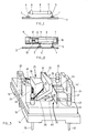
- fuses used for printed circuit boards are those shown, for example, in Figures 1 and 2.
- the conductive tracks 1 and 2 provided on the insulating support 3 are welded, the wires 4 and 5 welded respectively on the covers 6 and 7 covering the ends of the tube 8 in which is housed the fusible wire welded by its end to the covers.
- This fuse is not only fragile, but it generally comprises an opaque tube 8, so that the melting of the fusible wire is not visible.
- This tube 8 With a transparent material, but this would only allow it to be searched with a great deal of pain and loss of time.
- the tube 8 with fusible wire mounted between the covers 6 and 7 is housed in a cartridge 9, the bottom 10 of which has a conductive inner wall carrying the wire 5 is to be welded to the conductive track 1, while in the other end of the cartridge 9 is screwed a plug 11 in a thread 12 of a conductive part 13 to which is fixed the wire 4 to be welded to the track 2 support 3.
- This device has the drawback of the previous one and, moreover, it is bulky.
- the problem which is the basis of the invention is to produce a fuse security device for printed circuit cards which is not only compact, but which makes it possible to signal both the defective card and on it, the specific fuse that worked by blowing its wire.
- this second pair of pins is located in the electrical circuit of an optical or sound signaling means, the user can immediately identify the defective card, and by the means indicated below, identify on the defective card, the defective fuse .
- this device is characterized in that the cursor carries a contact device having substantially the shape of a U, one branch of which extends transversely to the path of the cursor, the bottom of which is provided with an opening for the passage of a slider stud, the transverse branch of said contact element being provided with two lateral lamellae, the slider stud being guided in a groove made in the base and the two lateral lamellas arranged at right and left other of said opening being intended to be guided in two other lateral grooves of the base.
- notches which block the two lateral tongues of the contact device when the contact blade comes to bear against the second pair of pins, in a curved position between them.
- the cursor preferably made of a ceramic material, comprises a projecting part of prismatic shape with convex front surface, over which the fusible wire passes, a spring being armed between the face opposite to the previous one and a corresponding part of the base.
- the base has a wall identical to that against which the spring bears, the assembly of these two walls serving for the fitting of a cover plate serving for closing the safety device, the assembly being capped. of a cover engaged by friction.
- the device of the invention is arranged so that the closure plate as well as the cover, respectively comprise an opening which is located in line with the projecting part of the cursor allowing the observation of the latter when the cursor is in its position armed by the fusible wire.
- the flexible blade carries a front steel plate in front of a permanent magnet carried by the base, between the second pair of dowels and against which the steel plate sticks, when the wire melts , by bending between these pins under the action of the relaxed spring.
- said means for blocking the flexible blade associated with the cursor, in the position in which it establishes the electrical connection between said second pair of pins are cons formed by a second spring distinct from that which is provided for the propulsion of the cursor at the melting of the fusible wire and acting in a direction which is perpendicular to the direction of the action of said propulsion spring of the cursor, said flexible blade being moved in its curved position between said secondary pair of pins, under the action of said second spring, upon the removal of a locking mechanism involved in the melting of the fusible wire.
- said blocking means comprise a cage with slots for guiding the flexible blade held in its position away from said second pair of pins, with arming of the second spring, by two balls locked on a chamfer of the cage by an underlying piston associated with the cursor and adapted to disengage from the balls when the fusible wire melts when the cursor propulsion spring is released.
- the device according to the invention is produced with a molded plastic base of square shape and of small dimension, for example of the order of 10 mm, its height being 7 mm, for pins 4 mm long.
- the reference 14 designates the base of the device which is a piece of molded plastic material provided with a first pair of pins 15 and 16, as well as a second pair of pins 17 and 18, these pins being molded in the mass of plastic material and being intended to be pressed into corresponding sockets provided at the level of the conductive tracks concerned of a printed circuit board, or to be soldered directly on the tracks of the circuit to be checked.
- Pins 15, 16, 17 and 18 are continued in the upper face of the base by pins respectively designated by 19, 20, 21 and 22.
- This slider 25 is a ceramic piece comprising a bottom 26 provided with a vertical wall element 27 with a convex front face 28 and with a flat inner face 29, and, at a certain distance from this, the bottom 26 carries a block of general prismatic appearance, the front face 31 of which is concave.
- a contact element shown in FIG. 3 A and designated by the general reference 32 is secured to the cursor.
- This contact element made of a material which is good conductor of electricity has the general shape of a U.
- One, 33, of the branches of the contact element 32 constitutes a contact blade whose flexibility is increased by two grooves 34 and 35 formed at the elbow formed with the bottom or transverse branch 36 of the contact element 32.
- the contact element 32 is adapted to be fixed to the cursor 25, as shown in FIG. 3, which cursor 25 has in the lower face of its bottom 26 a non-visible stud, which passes through the bore 39 of the branch transverse 36 of the contact element and is engaged in a central groove 42 formed in the upper face of the base 14, two other lateral grooves 43 and 44 arranged on either side of the groove 42, serving to guide the side tabs 40 and 41.
- the cursor 25 can either be disposed between the contact blade 33 of the contact element 32 and its second branch 39, or the latter can come to be housed in a slot, not shown, formed in the cursor 25, preferably at the during its manufacture.
- grooves 43 and 44 respectively have catch notches 44 and 47 located at a certain distance from the pins 21 and 22, as will be explained in Regarding the operating mode described below, after having noted that a spring 48, preferably helical, is provided between the rear face of the slider 25 and the wall element 23.
- the closing plate 49 On the vertical walls 23 and 24 is fixed the closing plate 49, preferably made with a ceramic, and provided with an opening 50 which is located in line with the prismatic boss 30 when the latter is in its position shown in the FIG. 3, this plate closing the cut-off device of the invention to prevent the possible passage of an arc which could occur during cut-off, while the assembly thus closed is capped with a cover 51 (FIG. 4) molded plastic material and comprising an opening 52 situated in line with the opening 50 of the closing plate 49 '.
- a fusible wire 49 of the single or multi-wire type is welded to the pins 19 and 20 passing over the concave face 31 of the prismatic block 30, thus retaining the cursor 25 in a first position in which the spring 48 is compressed.
- the cursor 25 is propelled by the spring 48 towards the pins 21 and 22 while being guided in the grooves 42, 43 and 44 by the stud not shown and by the tabs 40 and 41 which protrude from the stop notches 46 and 47 after the contact blade 33 comes to bear against the pins 21, 22, bringing them together electrically and thus completing the circuit of the conductive track with a signaling circuit optical or audible or command of a relay authorizing a cut-off or any other command or control function.
- the contact blade 33 curves between the latter to ensure good contact which is maintained by, the catch notches 46 and 47 which oppose any return of the contact blade 33 in a flat position.
- the prismatic boss 30 which can carry a green patch is visible through the openings 50 and 52, the melting of the wire 49 can be identified by the absence of said boss 30 at these openings.
- the reference 14 designates the base made of insulating material, the base in which the cursor 25 is provided.
- This is a ceramic part comprising a bottom 26 provided with an element of vertical walls 27 with a front face 28 and an internal face 29, and, at a certain distance from this, the bottom 26 carries a prismatic block whose the front face 31 is concave.
- the fusible wire 49 passes on this concave front face 31 and it is hooked to the first pair of pins 19 and 20, by arming the spring 48 housed in a cavity 101 of the cursor 25 and bearing against a fixed stop 102 carried by the base 14.
- a flexible blade 103 to the middle part of which is fixed by screws or rivets 104 and 105, a plate of steel 106, while opposite it, the base 14 carries a permanent magnet 107 located between the second pair of pegs 21 and 22.
- This second chamber 118 has a bottom with two chamfers 119 and 120 which open into an underlying cavity 121. On these chamfers are arranged two balls 122 and 123 located on either side of the axial rod 113 associated with the cursor, the mounting of the chamfer, the diameters of the balls and the cross section of the axial rod being chosen so that the balls 122 and 123 can only fall into the underlying cavity 121 when the axial rod 113 at least partially emerges from the second chamber.
- the cage 111 has in its side walls two slots 124 and 125 which serve as guides for the flexible blade 126 made with an electrically conductive material and extending above the pins 21 and 22 in the portion shown in FIG. 3 , by being applied against the balls 122 and 123 by a compression spring 127 which, moreover, bears against the bottom of the cover 128 of the device.
- the cursor 25 is propelled towards a stop 129 carried by the base 14, under the action of the spring 112 which relaxes and which drives the piston 114 and its axial rod 113.
- the second spring 127 expands by lowering the flexible blade 126 which comes to bear on the pins 21 and 22, bulging between them under the effect of the force exerted by said second spring 127.
- these two pins 21 and 22 are part of a circuit for signaling the melting of fusible wire, so that the user can quickly identify the faulty circuit breaker device and replace it with a new one.
Landscapes
- Fuses (AREA)
- Switch Cases, Indication, And Locking (AREA)
Applications Claiming Priority (4)
| Application Number | Priority Date | Filing Date | Title |
|---|---|---|---|
| FR8316683 | 1983-10-20 | ||
| FR8316683A FR2553933B1 (fr) | 1983-10-20 | 1983-10-20 | Dispositifs fusibles destines notamment a etre montes sur des cartes a circuits imprimes |
| FR8414836 | 1984-09-27 | ||
| FR8414836A FR2570874A2 (fr) | 1984-09-27 | 1984-09-27 | Dispositifs fusibles destines notamment a etre montes sur des cartes a circuits imprimes |
Publications (3)
| Publication Number | Publication Date |
|---|---|
| EP0139581A2 true EP0139581A2 (de) | 1985-05-02 |
| EP0139581A3 EP0139581A3 (en) | 1985-10-02 |
| EP0139581B1 EP0139581B1 (de) | 1988-07-20 |
Family
ID=26223636
Family Applications (1)
| Application Number | Title | Priority Date | Filing Date |
|---|---|---|---|
| EP84402000A Expired EP0139581B1 (de) | 1983-10-20 | 1984-10-05 | Schmelzvorrichtungen, insbesondere bestimmt für die Anordnung auf Platten mit aufgedruckten Schaltungen |
Country Status (5)
| Country | Link |
|---|---|
| US (1) | US4599597A (de) |
| EP (1) | EP0139581B1 (de) |
| JP (1) | JPS60115121A (de) |
| DE (1) | DE3472855D1 (de) |
| DK (1) | DK487184A (de) |
Families Citing this family (51)
| Publication number | Priority date | Publication date | Assignee | Title |
|---|---|---|---|---|
| US8459157B2 (en) | 2003-12-31 | 2013-06-11 | Sd3, Llc | Brake cartridges and mounting systems for brake cartridges |
| US7350445B2 (en) | 2003-08-20 | 2008-04-01 | Sd3, Llc | Brake cartridge for power equipment |
| US7481140B2 (en) | 2005-04-15 | 2009-01-27 | Sd3, Llc | Detection systems for power equipment |
| US7100483B2 (en) | 2000-08-14 | 2006-09-05 | Sd3, Llc | Firing subsystem for use in a fast-acting safety system |
| US7836804B2 (en) | 2003-08-20 | 2010-11-23 | Sd3, Llc | Woodworking machines with overmolded arbors |
| US7712403B2 (en) | 2001-07-03 | 2010-05-11 | Sd3, Llc | Actuators for use in fast-acting safety systems |
| US7137326B2 (en) * | 2000-08-14 | 2006-11-21 | Sd3, Llc | Translation stop for use in power equipment |
| US20020017179A1 (en) | 2000-08-14 | 2002-02-14 | Gass Stephen F. | Miter saw with improved safety system |
| US7024975B2 (en) | 2000-08-14 | 2006-04-11 | Sd3, Llc | Brake mechanism for power equipment |
| US20050041359A1 (en) | 2003-08-20 | 2005-02-24 | Gass Stephen F. | Motion detecting system for use in a safety system for power equipment |
| US7377199B2 (en) | 2000-09-29 | 2008-05-27 | Sd3, Llc | Contact detection system for power equipment |
| US7610836B2 (en) * | 2000-08-14 | 2009-11-03 | Sd3, Llc | Replaceable brake mechanism for power equipment |
| US6857345B2 (en) | 2000-08-14 | 2005-02-22 | Sd3, Llc | Brake positioning system |
| US7509899B2 (en) | 2000-08-14 | 2009-03-31 | Sd3, Llc | Retraction system for use in power equipment |
| US9724840B2 (en) | 1999-10-01 | 2017-08-08 | Sd3, Llc | Safety systems for power equipment |
| US7210383B2 (en) | 2000-08-14 | 2007-05-01 | Sd3, Llc | Detection system for power equipment |
| US6880440B2 (en) | 2000-09-29 | 2005-04-19 | Sd3, Llc | Miter saw with improved safety system |
| US7827890B2 (en) | 2004-01-29 | 2010-11-09 | Sd3, Llc | Table saws with safety systems and systems to mount and index attachments |
| US7171879B2 (en) | 2001-07-02 | 2007-02-06 | Sd3, Llc | Discrete proximity detection system |
| US20030056853A1 (en) | 2001-09-21 | 2003-03-27 | Gass Stephen F. | Router with improved safety system |
| US6945148B2 (en) | 2000-09-29 | 2005-09-20 | Sd3, Llc | Miter saw with improved safety system |
| US8065943B2 (en) | 2000-09-18 | 2011-11-29 | Sd3, Llc | Translation stop for use in power equipment |
| US6920814B2 (en) | 2000-08-14 | 2005-07-26 | Sd3, Llc | Cutting tool safety system |
| US7707920B2 (en) | 2003-12-31 | 2010-05-04 | Sd3, Llc | Table saws with safety systems |
| US6945149B2 (en) | 2001-07-25 | 2005-09-20 | Sd3, Llc | Actuators for use in fast-acting safety systems |
| US7284467B2 (en) | 2000-08-14 | 2007-10-23 | Sd3, Llc | Apparatus and method for detecting dangerous conditions in power equipment |
| US7197969B2 (en) | 2001-09-24 | 2007-04-03 | Sd3, Llc | Logic control with test mode for fast-acting safety system |
| US7472634B2 (en) | 2003-08-20 | 2009-01-06 | Sd3, Llc | Woodworking machines with overmolded arbors |
| US7000514B2 (en) | 2001-07-27 | 2006-02-21 | Sd3, Llc | Safety systems for band saws |
| US7353737B2 (en) | 2001-08-13 | 2008-04-08 | Sd3, Llc | Miter saw with improved safety system |
| US7308843B2 (en) * | 2000-08-14 | 2007-12-18 | Sd3, Llc | Spring-biased brake mechanism for power equipment |
| US6957601B2 (en) | 2000-08-14 | 2005-10-25 | Sd3, Llc | Translation stop for use in power equipment |
| US7350444B2 (en) | 2000-08-14 | 2008-04-01 | Sd3, Llc | Table saw with improved safety system |
| US7600455B2 (en) | 2000-08-14 | 2009-10-13 | Sd3, Llc | Logic control for fast-acting safety system |
| US6877410B2 (en) | 2000-09-29 | 2005-04-12 | Sd3, Llc | Miter saw with improved safety system |
| US7231856B2 (en) | 2001-06-13 | 2007-06-19 | Sd3, Llc | Apparatus and method for detecting dangerous conditions in power equipment |
| US7290472B2 (en) | 2002-01-14 | 2007-11-06 | Sd3, Llc | Miter saw with improved safety system |
| US7055417B1 (en) | 1999-10-01 | 2006-06-06 | Sd3, Llc | Safety system for power equipment |
| US9927796B2 (en) | 2001-05-17 | 2018-03-27 | Sawstop Holding Llc | Band saw with improved safety system |
| US7536238B2 (en) | 2003-12-31 | 2009-05-19 | Sd3, Llc | Detection systems for power equipment |
| US7225712B2 (en) | 2000-08-14 | 2007-06-05 | Sd3, Llc | Motion detecting system for use in a safety system for power equipment |
| US7077039B2 (en) | 2001-11-13 | 2006-07-18 | Sd3, Llc | Detection system for power equipment |
| US6994004B2 (en) | 2000-09-29 | 2006-02-07 | Sd3, Llc | Table saw with improved safety system |
| US20030037651A1 (en) | 2001-08-13 | 2003-02-27 | Gass Stephen F. | Safety systems for power equipment |
| US8061245B2 (en) | 2000-09-29 | 2011-11-22 | Sd3, Llc | Safety methods for use in power equipment |
| US20040195512A1 (en) * | 2000-05-16 | 2004-10-07 | Crosetto Dario B. | Method and apparatus for anatomical and functional medical imaging |
| US6826988B2 (en) | 2000-09-29 | 2004-12-07 | Sd3, Llc | Miter saw with improved safety system |
| US6813983B2 (en) | 2000-09-29 | 2004-11-09 | Sd3, Llc | Power saw with improved safety system |
| US6873243B1 (en) * | 2001-10-18 | 2005-03-29 | Cisco Technology, Inc. | Small-footprint fuse |
| US7347851B1 (en) | 2004-03-09 | 2008-03-25 | Leo B Kriksunov | Needleless hypodermic jet injector apparatus and method |
| DE102018118247B3 (de) | 2018-07-17 | 2019-09-19 | Borgwarner Ludwigsburg Gmbh | Thermische Sicherung |
Family Cites Families (8)
| Publication number | Priority date | Publication date | Assignee | Title |
|---|---|---|---|---|
| FR464852A (fr) * | 1913-11-12 | 1914-04-02 | Marie Arsene Thiebaud | Coupe-circuit avertisseur |
| US3286062A (en) * | 1965-09-03 | 1966-11-15 | Fuse Indicator Corp | Mechanical indicating fuseholder |
| US3437972A (en) * | 1967-02-27 | 1969-04-08 | Mc Graw Edison Co | Protectors for electric circuits |
| US3696316A (en) * | 1970-12-31 | 1972-10-03 | Daito Tsushinki Kk | Fuses and fuseholders |
| FR2321750A1 (fr) * | 1975-08-22 | 1977-03-18 | Commissariat Energie Atomique | Perfectionnement apporte aux circuits secondaires d'un reacteur nucleaire |
| US4023133A (en) * | 1976-03-15 | 1977-05-10 | The Chase-Shawmut Company | Blown fuse indicator |
| DE2651552A1 (de) * | 1976-11-11 | 1978-05-18 | Siemens Ag | Sicherungsaufnahmeelement |
| AT371946B (de) * | 1979-09-06 | 1983-08-10 | Wickmann Werke Ag | Schmelzsicherung, insbesondere fuer gedruckte schaltungen |
-
1984
- 1984-10-05 EP EP84402000A patent/EP0139581B1/de not_active Expired
- 1984-10-05 DE DE8484402000T patent/DE3472855D1/de not_active Expired
- 1984-10-11 DK DK487184A patent/DK487184A/da unknown
- 1984-10-15 US US06/660,887 patent/US4599597A/en not_active Expired - Fee Related
- 1984-10-19 JP JP59218740A patent/JPS60115121A/ja active Pending
Also Published As
| Publication number | Publication date |
|---|---|
| DE3472855D1 (en) | 1988-08-25 |
| US4599597A (en) | 1986-07-08 |
| DK487184A (da) | 1985-04-21 |
| EP0139581B1 (de) | 1988-07-20 |
| JPS60115121A (ja) | 1985-06-21 |
| EP0139581A3 (en) | 1985-10-02 |
| DK487184D0 (da) | 1984-10-11 |
Similar Documents
| Publication | Publication Date | Title |
|---|---|---|
| EP0139581B1 (de) | Schmelzvorrichtungen, insbesondere bestimmt für die Anordnung auf Platten mit aufgedruckten Schaltungen | |
| FR2660794A1 (fr) | Mecanisme de commande d'un disjoncteur electrique. | |
| FR2612340A1 (fr) | Borne de raccordement multiple pour appareil electrique modulaire | |
| EP0106768B1 (de) | Verbindungsvorrichtung für einen elektrischen Leiter | |
| CA1244069A (fr) | Dispositif d'alimentation electrique a disjoncteur et prise electrique incorporant ce dispositif | |
| FR2685544A1 (fr) | Cartouche a fusibles du type a indicateur de fonctionnement. | |
| EP0540398A1 (de) | Verbindungsbaugruppe vom Typ Schaltungsschleife | |
| FR2641907A3 (fr) | Connecteur pourvu d'un dispositif de commutation | |
| FR2553933A1 (fr) | Dispositifs fusibles destines notamment a etre montes sur des cartes a circuits imprimes | |
| FR2570869A1 (fr) | Perfectionnement aux ensembles de contact des interrupteurs a coupure | |
| EP0040384A1 (de) | Vorrichtung zur Verriegelung-Entriegelung eines Kabels auf einer Isolatorkappe | |
| US4559513A (en) | Trigger mechanism for dual-element fuse | |
| FR2570874A2 (fr) | Dispositifs fusibles destines notamment a etre montes sur des cartes a circuits imprimes | |
| FR2576458A2 (fr) | Cosse femelle pour connexion electrique | |
| EP0773572A1 (de) | Elektrisches Gerät mit Schnappeinschaltung | |
| FR2591030A1 (fr) | Dispositif a fibres optiques pour le controle du fonctionnement des cartouches a fusibles | |
| EP0736945B1 (de) | Trenner-Begrenzungs-Schutz für dreiphasige elektrische Transformatoren | |
| EP0479694B1 (de) | Stromverteilungsvorrichtung für die elektrische Energie einer Verteilertafel | |
| FR2544125A1 (fr) | Interrupteur electrique de securite a tige conductrice amovible | |
| FR2569047A1 (fr) | Porte-fusible antichoc | |
| FR2523761A1 (fr) | Interrupteur electrique | |
| EP0290300B1 (de) | Schnellverbindungseinrichtung von gedruckten Schaltungen für Modulgehäuse | |
| FR2610727A1 (fr) | Dispositif pour la detection selective de secousses ou chocs et leur signalisation sonore et lumineuse | |
| EP1033735A1 (de) | Elektronischer Auslöser mit einem abnehmbaren Langzeitverzögerungsmodul mit einer Ein- und Ausschaltungsfunktion | |
| FR2620567A1 (fr) | Cartouche a couteaux pour coupe-circuit |
Legal Events
| Date | Code | Title | Description |
|---|---|---|---|
| PUAI | Public reference made under article 153(3) epc to a published international application that has entered the european phase |
Free format text: ORIGINAL CODE: 0009012 |
|
| AK | Designated contracting states |
Designated state(s): BE CH DE GB IT LI LU NL SE |
|
| RTI1 | Title (correction) | ||
| PUAL | Search report despatched |
Free format text: ORIGINAL CODE: 0009013 |
|
| AK | Designated contracting states |
Designated state(s): BE CH DE GB IT LI LU NL SE |
|
| 17P | Request for examination filed |
Effective date: 19851028 |
|
| 17Q | First examination report despatched |
Effective date: 19870619 |
|
| RAP1 | Party data changed (applicant data changed or rights of an application transferred) |
Owner name: CEHESS TECHNOLOGIES |
|
| GRAA | (expected) grant |
Free format text: ORIGINAL CODE: 0009210 |
|
| AK | Designated contracting states |
Kind code of ref document: B1 Designated state(s): BE CH DE GB IT LI LU NL SE |
|
| PG25 | Lapsed in a contracting state [announced via postgrant information from national office to epo] |
Ref country code: SE Effective date: 19880720 Ref country code: NL Effective date: 19880720 Ref country code: IT Free format text: LAPSE BECAUSE OF FAILURE TO SUBMIT A TRANSLATION OF THE DESCRIPTION OR TO PAY THE FEE WITHIN THE PRESCRIBED TIME-LIMIT;WARNING: LAPSES OF ITALIAN PATENTS WITH EFFECTIVE DATE BEFORE 2007 MAY HAVE OCCURRED AT ANY TIME BEFORE 2007. THE CORRECT EFFECTIVE DATE MAY BE DIFFERENT FROM THE ONE RECORDED. Effective date: 19880720 |
|
| REF | Corresponds to: |
Ref document number: 3472855 Country of ref document: DE Date of ref document: 19880825 |
|
| GBT | Gb: translation of ep patent filed (gb section 77(6)(a)/1977) | ||
| PG25 | Lapsed in a contracting state [announced via postgrant information from national office to epo] |
Ref country code: LU Free format text: LAPSE BECAUSE OF NON-PAYMENT OF DUE FEES Effective date: 19881031 Ref country code: BE Effective date: 19881031 |
|
| NLV1 | Nl: lapsed or annulled due to failure to fulfill the requirements of art. 29p and 29m of the patents act | ||
| BERE | Be: lapsed |
Owner name: CEHESS TECHNOLOGIES Effective date: 19881031 |
|
| PLBE | No opposition filed within time limit |
Free format text: ORIGINAL CODE: 0009261 |
|
| STAA | Information on the status of an ep patent application or granted ep patent |
Free format text: STATUS: NO OPPOSITION FILED WITHIN TIME LIMIT |
|
| 26N | No opposition filed | ||
| PGFP | Annual fee paid to national office [announced via postgrant information from national office to epo] |
Ref country code: GB Payment date: 19930928 Year of fee payment: 10 Ref country code: CH Payment date: 19930928 Year of fee payment: 10 |
|
| PGFP | Annual fee paid to national office [announced via postgrant information from national office to epo] |
Ref country code: DE Payment date: 19931208 Year of fee payment: 10 |
|
| PG25 | Lapsed in a contracting state [announced via postgrant information from national office to epo] |
Ref country code: GB Effective date: 19941005 |
|
| PG25 | Lapsed in a contracting state [announced via postgrant information from national office to epo] |
Ref country code: LI Effective date: 19941031 Ref country code: CH Effective date: 19941031 |
|
| GBPC | Gb: european patent ceased through non-payment of renewal fee |
Effective date: 19941005 |
|
| REG | Reference to a national code |
Ref country code: CH Ref legal event code: PL |
|
| PG25 | Lapsed in a contracting state [announced via postgrant information from national office to epo] |
Ref country code: DE Effective date: 19950701 |