EP0139591A2 - Ausstellbare Einrichtung zum Erhöhen eines Fahrzeuges oder eines Gehäuses - Google Patents
Ausstellbare Einrichtung zum Erhöhen eines Fahrzeuges oder eines Gehäuses Download PDFInfo
- Publication number
- EP0139591A2 EP0139591A2 EP84402082A EP84402082A EP0139591A2 EP 0139591 A2 EP0139591 A2 EP 0139591A2 EP 84402082 A EP84402082 A EP 84402082A EP 84402082 A EP84402082 A EP 84402082A EP 0139591 A2 EP0139591 A2 EP 0139591A2
- Authority
- EP
- European Patent Office
- Prior art keywords
- panels
- cover
- longitudinal
- edges
- transverse
- Prior art date
- Legal status (The legal status is an assumption and is not a legal conclusion. Google has not performed a legal analysis and makes no representation as to the accuracy of the status listed.)
- Granted
Links
Images


Classifications
-
- B—PERFORMING OPERATIONS; TRANSPORTING
- B60—VEHICLES IN GENERAL
- B60P—VEHICLES ADAPTED FOR LOAD TRANSPORTATION OR TO TRANSPORT, TO CARRY, OR TO COMPRISE SPECIAL LOADS OR OBJECTS
- B60P3/00—Vehicles adapted to transport, to carry or to comprise special loads or objects
- B60P3/32—Vehicles adapted to transport, to carry or to comprise special loads or objects comprising living accommodation for people, e.g. caravans, camping, or like vehicles
- B60P3/34—Vehicles adapted to transport, to carry or to comprise special loads or objects comprising living accommodation for people, e.g. caravans, camping, or like vehicles the living accommodation being expansible, collapsible or capable of rearrangement
Definitions
- the present invention relates to a folding device intended for raising a vehicle or a passenger compartment.
- Various folding devices are known which are intended for raising a vehicle so as to increase the height available inside the vehicle if necessary.
- one which comprises a roof panel, one of the edges of which is hinged to the roof of the vehicle, two triangular panels, one of whose edges is hinged to the roof of the vehicle, and a rectangular transverse panel, the l 'one of its edges is articulated on the roof of the vehicle, these last three panels forming the side walls of the raising device being foldable independently.
- Others are also known, in particular from patents FR 2 202 794 and US 4 262 956, which are in the unfolded position in the form of parallelepipeds and the four side walls of which are foldable independently of one another.
- the present invention which aims to eliminate the drawbacks of the state of the art, provides a folding device intended for raising a vehicle or a passenger compartment, the structure of which allows it to be unfolded or folded in a simple manner and makes it possible to make it waterproof without any particular difficulty in a simple manner.
- the transverse edge of said cover opposite said transverse panel is hingedly mounted on said vehicle and means are mounted between this cover and said transverse panel, means which are adapted so that said cover moves vertically by pivoting around its transverse hinged edge, simultaneously with the folding and unfolding movements of said panels.
- the connecting means between said cover and said transverse panel can advantageously be formed by rods whose ends are articulated respectively on said cover and said transverse panel, outside this transverse panel, these rods extending inside of said cover when the latter is in the low position.
- the device according to the present invention preferably comprises means mounted between said cover and said transverse panels and adapted so that said cover moves vertically simultaneously with the folding and unfolding movements of said panels, these connecting means between said cover and said transverse panels being preferably formed by slides carried by said transverse panels and which cooperate with longitudinal slides mounted on said cover.
- said cover is preferably in the form of a bowl, the upper part of said panels coming to bear against the inner face of the peripheral walls of said cover when said panels are in the unfolded position and the cover in high position, locking means in its unfolded position being provided between said longitudinal panels and said cover.
- said connecting means could also be formed by rods connecting the transverse panels to the cover, inside.
- the peripheral lower edge of said cover in its low position, extends in the vicinity of the wall of the vehicle or is in contact there and a peripheral seal is provided between this edge of said cover and the wall of the vehicle, said panels extending below this cover.
- a peripheral seal is provided between said panels and said cover, to create a seal when these panels are in their unfolded position and the cover in its high position.
- seals are provided between the adjacent edges of said panels and seals are provided between the bottom edges of said panels and the vehicle.
- the folding device preferably comprises actuating means making it possible to move said cover in the vertical direction, these actuating means possibly advantageously being formed by pneumatic cylinders mounted between said cover and the vehicle, these jacks are extending inside the cover when the latter is in the low position.
- the folding device preferably comprises a support in the form of an intermediate cover between said longitudinal and transverse panels and the vehicle and fixed to the edge of an opening in the wall of the vehicle.
- the angles between the longitudinal edges of said longitudinal panels and their second edge (s) as well as the angles between the first and second edges of said intermediate panels are equal and that said opposite edges of said panels transverse are parallel.
- said panels in the folded position, said panels can be supported on each other.
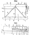
- the folding device shown in FIGS. 1 to 5 and generally identified by the reference 1 is intended for raising a vehicle 2 whose aa roof only shows its roof 3 which, in the example shown, has a flat horizontal upper wall 4.
- the wall 4 of the roof 3 has a rectangular opening 5.
- the device 1 firstly comprises an intermediate support of rectangular shape comprising two longitudinal members 6 which are fixed on two opposite edges of the opening 5 and two cross members 7 which are fixed on the other two opposite edges of the opening 5.
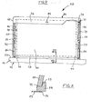
- the device 1 comprises two longitudinal panels 8 which have lower longitudinal edges 9 respectively mounted in an articulated manner on the side members 6 by means of hinges 10, as shown in an enlarged manner Figure 5.
- the longitudinal panels 8 are trapezoidal and have two opposite edges II and 12 which extend from the ends of the lower longitudinal edge 9, at 45 ° relative to the latter.
- the device 1 also comprises four identical triangular panels 13, the base 14 and the side 15 adjacent to this base form an angle equal to 45 °.
- Two intermediate panels 13 are associated with each of the longitudinal panels 8 so that their edges 14 are articulated on their edges 11 and 12 by means of hinges 16 and that their corners situated between their edges 14 and 15 are adjacent to the longitudinal edges 9 of the longitudinal panels 8.
- the longitudinal panels 8 and the intermediate panels 13 which they carry are in the same plane, they determine, in the example shown, rectangular walls generally identified by the reference 17.
- the device 1 also comprises two transverse panels 18 which, as can be seen in FIG. 2, are in the example shown rectangular, these transverse panels 18 having two opposite parallel edges 19 which are mounted in an articulated manner, via hinges 20, on the edges 15 of the intermediate panels 13 located one opposite the other and carried by the longitudinal panels 8.
- the edges 19 of the transverse panels 18 have substantially the same length as the edges 15 of the intermediate panels 13
- the longitudinal panels 8 extend in the same plane as the intermediate panels 13 which they carry, so well that the transverse panels 18 and the rectangular walls 17 are vertical and determine a rectangular parallelepiped.
- the device 1 also comprises a cover generally identified by the reference 21 which is in the form of a bowl of rectangular section and which has longitudinal walls 22 and transverse walls 23.
- This cover 21 is arranged so that its bottom 21a extends horizontally and its side walls 22 and 23 extend outside and at a distance from the upper part of said panels when the latter are in said unfolded position and delimit a rectangular parallelepiped, as can be seen in the Figures 1 and 2.
- the device 1 also comprises jacks 27 which are active in one direction and which have the purpose of moving the cover 21 upwards.
- jacks 27 which are active in one direction and which have the purpose of moving the cover 21 upwards.
- the device 1 In order to move the cover 21 downwards, the device 1 comprises two cables 28, the ends of which are fixed respectively to the inner face of the transverse walls 23 of the cover 21, in their middle, and which extend outside the transverse panels 18 to be subsequently carried by sheaths 29 which extend through crosspieces 7 and which run, from the inside, these crosspieces 7 as well as one of the side members 5 to reach a winch or reel 30 shown schematically in FIG. 3, this winch 30 being accessible from inside the vehicle 2.
- the device 1 delimits an interior space of substantially parallelepiped shape which extends above the opening 5 of the roof 4 of the vehicle and which raises the passenger compartment of this vehicle by the height that separates the roof 4 from the wall 2la forming the bottom of the cover 21, the side walls of this raised space being formed longitudinally by the longitudinal panels 8 and the intermediate panels 13 and transversely by the transverse panels 18 as well as through the part of the side walls 22 and 23 of the cover 21 adjacent to its bottom 21a:
- the cables 28 can be pulled so as to move the cover 21 against the jacks 27.
- the cover 21 being moved downwards, the longitudinal panels 8 fold inward one towards the other by pivoting around the hinges 10, the transverse panels 18 fold back towards each other inwards and the intermediate panels 13 fold over so that their outer face is directed towards the outer face of the longitudinal panels 8 and that their inner face folds back towards the inner face of the transverse panels 18, by pivoting around the hinges 16 and 20, while the rollers 25 move in the slides 24 by approaching two by two.
- the longitudinal panels 8, the longitudinal panels 13 and the transverse panels 18 are arranged horizontally and are stacked in the following manner. Both panels 13 carried by the longitudinal panels 8 extend above the longitudinal panels 8 and the transverse panels 18 extend above the intermediate panels 13 which are respectively connected to them while the lower edges of the walls 22 and 23 of the cover 21 come in the vicinity or are in contact with the exterior face of the roof 4 of the vehicle, around the intermediate support formed by the side members 6 and the cross members 7. This folded position is shown in FIG. 3.
- the jacks 27 occupy an inclined position and extend, like the cables 28, inside the cover 21.
- the jacks 27 push the cover 21 upwards and, thanks to the slides 24 and the rollers 25, the panels 8, 13 and 18 deploy by moving in the opposite direction to the directions mentioned above so as to return to their initial unfolded position.
- the lower edge of the walls 22 and 23 of the cover 21 is provided with a peripheral seal 31 creating a seal between this cover 21 and the exterior face of the roof 4 of the vehicle 2.
- the lower edges 9 of the longitudinal panels 8 carry linear seals 33 which, when these panels 8 are in the unfolded position, create a seal between these longitudinal panels 8 and the side members 6 Identical seals are provided between the lower edge of the transverse panels 8 and the crosspieces 7, these seals not being visible in the figures.
- the inner face of the side walls 22 and 23 of the cover 21 carries a peripheral seal 34 which creates a tight connection between the upper edges of the panels 8, 13 and 18 and the cover when the device 1 is in the unfolded position.
- locking systems 35 have been provided, constituted for example by hooks which prevent the upper edges of the longitudinal panels 8 from moving away from the side walls 22 of the cover 21.
- the device 1 is, in its unfolded position, completely sealed and non-deformable.
- FIG. 6 we will now describe a simplified folding device generally identified by the reference 50 which is intended for raising a vehicle 51 which is shown in the drawing only its roof 52 which has, in the example shown, a flat horizontal upper wall 53 in which is formed, as before, a rectangular opening 54.
- the device 50 comprises an intermediate support in the form of a rectangular frame which comprises two longitudinal members 55 and 56 which are fixed on two opposite edges of the opening 54 and two crosspieces 57 and 58 which are fixed on the other two opposite edges of the opening 54.
- the device 1 comprises two longitudinal panels 59 which have lower longitudinal edges 60 respectively mounted in an articulated manner on the longitudinal members 55 and 56 by means of hinges 61, the mounting of these longitudinal panels 59 on the longitudinal members 55 and 56 being the same than that of the longitudinal panels 8 on the longitudinal members 6 of the previous example shown in an enlarged manner in FIG. 5.
- the panels 59 are substantially rectangular in shape and have two other edges 62 and 63 which form an obtuse angle, the edges 62 of these longitudinal panels 59 converging towards the ends of the side members 55 and 56 situated on the side of the cross member 58.
- the device 50 also comprises two identical intermediate panels 64 which are triangular in shape and which have two adjacent edges 65 and 66 which form an angle equal to the angle formed by the edges 60 and 62 of the longitudinal panels 59.
- the edges 65 of the intermediate panels 64 are articulated on the edges 62 of the longitudinal panels 59 by means of hinges 67.
- the third edges 68 of the intermediate panels 64 are substantially in alignment with the edges 63 of the longitudinal panels 59 so that they respectively form substantially triangles.
- the device 50 also comprises a transverse panel 69 which in the example shown is rectangular and two opposite edges 70 of which are hingedly mounted respectively on the edges 66 of the intermediate panels 64 by means of hinges 71.
- the hinges 67 and 71 are mounted in the same way as the hinges 16 visible in FIG. 4 of the previous example.
- the device 50 also comprises a cover generally identified by the reference 74 which is in the form of a cover of rectangular section and which has longitudinal walls 75 and transverse walls 76.
- the side walls of the cover 74 surround the upper part of the longitudinal panels 59, of the intermediate panels 64 and of the transverse panel 69 which come to bear against their inner face by means of a seal 77 when these panels are in the unfolded position. in which the longitudinal panels 59 and the intermediate panels 64 are aligned, the cover 74 then being in the high position, while in the folded position, the lower edge of the peripheral walls of the cover 74 come to bear against the upper face 53 of the vehicle 51, around and at a distance from the side members 55 and 56 and from the cross members 57 and 58.
- the transverse wall 76 of the cover 74 opposite the transverse wall 69 and adjacent to the cross member 57 is mounted, by its lower edge, on this cross member 57 via a transverse hinge 78 around which it can pivot.
- the cover 74 is linked to the transverse panel 69 by means of two links 79 whose ends are respectively articulated, transversely, on the opposite edges 70 of the transverse panel 69 and on the longitudinal walls 75 of the cover 74 in the vicinity of its transverse wall 76, inside.
- two pneumatic cylinders 80 are provided, the ends of which are articulated, transversely, between the side members 55 and 56 and the inner face of the longitudinal walls 75 of the cover 74.
- the device 50 In its unfolded position visible in FIGS. 6 and 7, the device 50 is such that the cover 74 is inclined in the direction of the cross-member 57, the longitudinal panels 59 and the intermediate panels 54 are aligned and the transverse panel 69 extends towards the top, the upper part of these panels extending inside the cover 74 and being in abutment against the inner face of three of its side walls by means of the seal 77, the device 50 being held in this position by locking systems, not shown, which holds the longitudinal panels 59 against the longitudinal walls 75 of the cover 74 and which can be constituted by the locking system 35 of the previous example.
- the device 50 can be folded up as follows.
- the cover 74 is pivoted down around its hinge 78, exerting forces on the 'against pneumatic cylinders 80.
- the panels 59, 64 and 68 perform movements jointly with the cover 64 by means of the links 79 in the following manner.
- the longitudinal panels 59 and the transverse panel 69 fold inwards while the outside face of the intermediate panels 64 folds down towards the outside face of the longitudinal panels 59 and that the inside face of the intermediate panels 64 folds back towards the inside face of the transverse panel 69.
- any known locking system can be provided, acting for example between the cross-member 59 and the transverse wall 76 of the cover 50 carrying the handle 81, this system not being shown in the figures.
- the roof wall 74a of the cover 74 has an upwardly swollen portion 74b over substantially half of its length from its transverse wall 76 carrying the hinge 78 so as to increase in the lower part of the cover 74 in the unfolded position, a greater available height.
- the present invention is not limited to the raising devices described above. Indeed, we could very well have provided devices' of different general shape when they are in the unfolded position, devices capable of fitting on vehicle roofs of any shape, taking care to modify the shape of the cover, means for actuating the cover and the different panels or arranged in different places, connection means between the cover and the different panels or arranged in different places.
- the panels can have openings. Many other alternative embodiments are possible.
Landscapes
- Engineering & Computer Science (AREA)
- Health & Medical Sciences (AREA)
- Public Health (AREA)
- Transportation (AREA)
- Mechanical Engineering (AREA)
- Body Structure For Vehicles (AREA)
- Tents Or Canopies (AREA)
- Load-Engaging Elements For Cranes (AREA)
- Jib Cranes (AREA)
- Fittings On The Vehicle Exterior For Carrying Loads, And Devices For Holding Or Mounting Articles (AREA)
- Vehicle Step Arrangements And Article Storage (AREA)
- Vehicle Cleaning, Maintenance, Repair, Refitting, And Outriggers (AREA)
- Vehicle Waterproofing, Decoration, And Sanitation Devices (AREA)
Priority Applications (1)
| Application Number | Priority Date | Filing Date | Title |
|---|---|---|---|
| AT84402082T ATE31904T1 (de) | 1983-10-17 | 1984-10-16 | Ausstellbare einrichtung zum erhoehen eines fahrzeuges oder eines gehaeuses. |
Applications Claiming Priority (2)
| Application Number | Priority Date | Filing Date | Title |
|---|---|---|---|
| FR8316491 | 1983-10-17 | ||
| FR8316491A FR2553348B1 (fr) | 1983-10-17 | 1983-10-17 | Dispositif repliable destine a la surelevation d'un vehicule ou d'un habitacle |
Publications (3)
| Publication Number | Publication Date |
|---|---|
| EP0139591A2 true EP0139591A2 (de) | 1985-05-02 |
| EP0139591A3 EP0139591A3 (en) | 1985-06-26 |
| EP0139591B1 EP0139591B1 (de) | 1988-01-13 |
Family
ID=9293220
Family Applications (1)
| Application Number | Title | Priority Date | Filing Date |
|---|---|---|---|
| EP84402082A Expired EP0139591B1 (de) | 1983-10-17 | 1984-10-16 | Ausstellbare Einrichtung zum Erhöhen eines Fahrzeuges oder eines Gehäuses |
Country Status (4)
| Country | Link |
|---|---|
| EP (1) | EP0139591B1 (de) |
| AT (1) | ATE31904T1 (de) |
| DE (1) | DE3468656D1 (de) |
| FR (1) | FR2553348B1 (de) |
Cited By (6)
| Publication number | Priority date | Publication date | Assignee | Title |
|---|---|---|---|---|
| GB2225358A (en) * | 1987-06-04 | 1990-05-30 | Nisar Sayed | Portable foldable shelter |
| US4973101A (en) * | 1989-02-06 | 1990-11-27 | Sagstetter William E | Add-on collapsible shelter for use on a motor vehicle |
| FR2653722A1 (fr) * | 1989-10-31 | 1991-05-03 | Coutanceau Gilles | Dispositif d'extension en hauteur d'une cellule d'habitation tractee et/ou portee et vehicule equipe de ce dispositif. |
| GB2333069A (en) * | 1998-01-08 | 1999-07-14 | Mclaren International Ltd | Mobile hospitality units |
| FR2779404A1 (fr) | 1998-06-04 | 1999-12-10 | Jacques Perez | Vehicule de transport a hauteur de caisse reglable |
| CN111231908A (zh) * | 2020-03-27 | 2020-06-05 | 江苏捷诚车载电子信息工程有限公司 | 快速扩展厢舱大平台及收放方法 |
Family Cites Families (5)
| Publication number | Priority date | Publication date | Assignee | Title |
|---|---|---|---|---|
| US3212813A (en) * | 1964-07-27 | 1965-10-19 | Freeway Travelers Inc | Vehicle with extensible top |
| GB1385118A (en) * | 1972-10-17 | 1975-02-26 | Ci Autohomes Ltd | Elevating roof |
| GB1496314A (en) * | 1976-01-29 | 1977-12-30 | Ci Autohomes Ltd | Elevating roof |
| US4262956A (en) * | 1978-04-03 | 1981-04-21 | Kellam L Birt | Vehicle with raisable roof |
| DE2840487A1 (de) * | 1978-09-18 | 1980-03-27 | Weinsberg Karosseriewerke | Wohnmobil |
-
1983
- 1983-10-17 FR FR8316491A patent/FR2553348B1/fr not_active Expired
-
1984
- 1984-10-16 AT AT84402082T patent/ATE31904T1/de not_active IP Right Cessation
- 1984-10-16 DE DE8484402082T patent/DE3468656D1/de not_active Expired
- 1984-10-16 EP EP84402082A patent/EP0139591B1/de not_active Expired
Cited By (8)
| Publication number | Priority date | Publication date | Assignee | Title |
|---|---|---|---|---|
| GB2225358A (en) * | 1987-06-04 | 1990-05-30 | Nisar Sayed | Portable foldable shelter |
| US4973101A (en) * | 1989-02-06 | 1990-11-27 | Sagstetter William E | Add-on collapsible shelter for use on a motor vehicle |
| FR2653722A1 (fr) * | 1989-10-31 | 1991-05-03 | Coutanceau Gilles | Dispositif d'extension en hauteur d'une cellule d'habitation tractee et/ou portee et vehicule equipe de ce dispositif. |
| GB2333069A (en) * | 1998-01-08 | 1999-07-14 | Mclaren International Ltd | Mobile hospitality units |
| GB2333069B (en) * | 1998-01-08 | 2001-11-07 | Mclaren Internat Ltd | Hospitality unit |
| FR2779404A1 (fr) | 1998-06-04 | 1999-12-10 | Jacques Perez | Vehicule de transport a hauteur de caisse reglable |
| CN111231908A (zh) * | 2020-03-27 | 2020-06-05 | 江苏捷诚车载电子信息工程有限公司 | 快速扩展厢舱大平台及收放方法 |
| CN111231908B (zh) * | 2020-03-27 | 2024-04-23 | 江苏捷诚车载电子信息工程有限公司 | 快速扩展厢舱大平台及收放方法 |
Also Published As
| Publication number | Publication date |
|---|---|
| ATE31904T1 (de) | 1988-01-15 |
| EP0139591B1 (de) | 1988-01-13 |
| EP0139591A3 (en) | 1985-06-26 |
| DE3468656D1 (en) | 1988-02-18 |
| FR2553348A1 (fr) | 1985-04-19 |
| FR2553348B1 (fr) | 1987-12-24 |
Similar Documents
| Publication | Publication Date | Title |
|---|---|---|
| EP0371540B1 (de) | Behälterförmiges transportables Bauelement | |
| EP0139591B1 (de) | Ausstellbare Einrichtung zum Erhöhen eines Fahrzeuges oder eines Gehäuses | |
| FR2617449A1 (fr) | Perfectionnements aux unites mobiles habitables extensibles | |
| EP0534843A1 (de) | Gerüst für rechteckiges Zelt mit einem Satteldach | |
| WO2008110696A1 (fr) | Dispositif de protection pour un ascenseur et ascenseur comportant un tel dispositif | |
| WO2003013889A1 (fr) | Vehicule decouvrable a toit repliable | |
| LU85595A1 (fr) | Element de construction en forme de conteneur transportable et construction formee par assemblage de tels elements | |
| FR2573706A1 (fr) | Habitacle du type repliable et/ou demontable par exemple une caravane | |
| EP0147266B1 (de) | Streckbare und transportfähige bewohnbare Zelle | |
| EP0528725B1 (de) | Mobiler Boxring | |
| EP0880444B1 (de) | Zusammenfaltbare plattform und damit ausgerüstete mobile einheit | |
| WO1991011577A1 (fr) | Habitacle repliable | |
| EP0203128B1 (de) | Zusammenfaltbares und/oder zerlegbares häuschen | |
| EP2253562B1 (de) | Transportvorrichtung für vorgefertigte plattenförmige Elemente | |
| EP0741052B1 (de) | Gestell zur Abdeckung eines Nutzfahrzeuges mit einer bewegbaren Runge | |
| FR2797427A1 (fr) | Echelle articulee d'acces de quai a embarcation | |
| FR2853869A1 (fr) | Ensemble coffre a bagages et tente de toit pour vehicules | |
| FR2809057A1 (fr) | Agencement de coffre de vehicule automobile a toit repliable | |
| FR2841526A1 (fr) | Vehicule a volet arriere a deux positions ouvertes, ouverture volet a faible debattement ou ouverture du type "hobby" | |
| EP0008978A1 (de) | Fahrzeug, insbesondere Wohnwagen, mit einem Klappmöbel | |
| WO2023199185A1 (fr) | Module de vie déployable depuis un container. | |
| FR2685277A1 (fr) | Vehicule de transport bache. | |
| CA1279586C (fr) | Element de construction en forme de conteneur transportable et construction formee par assemblage de tels elements | |
| EP1057967A1 (de) | Tritthocker oder Trittleiter mit einer in der Mitte gelenkigen Plattform | |
| FR2841218A1 (fr) | Boitage a poignee a base de carton initialement plie et mis en forme par simple depliage |
Legal Events
| Date | Code | Title | Description |
|---|---|---|---|
| PUAI | Public reference made under article 153(3) epc to a published international application that has entered the european phase |
Free format text: ORIGINAL CODE: 0009012 |
|
| PUAL | Search report despatched |
Free format text: ORIGINAL CODE: 0009013 |
|
| AK | Designated contracting states |
Designated state(s): AT BE CH DE FR GB IT LI LU NL |
|
| AK | Designated contracting states |
Designated state(s): AT BE CH DE FR GB IT LI LU NL |
|
| 17P | Request for examination filed |
Effective date: 19851028 |
|
| 17Q | First examination report despatched |
Effective date: 19860418 |
|
| ITF | It: translation for a ep patent filed | ||
| GRAA | (expected) grant |
Free format text: ORIGINAL CODE: 0009210 |
|
| AK | Designated contracting states |
Kind code of ref document: B1 Designated state(s): AT BE CH DE FR GB IT LI LU NL |
|
| REF | Corresponds to: |
Ref document number: 31904 Country of ref document: AT Date of ref document: 19880115 Kind code of ref document: T |
|
| GBT | Gb: translation of ep patent filed (gb section 77(6)(a)/1977) | ||
| REF | Corresponds to: |
Ref document number: 3468656 Country of ref document: DE Date of ref document: 19880218 |
|
| NLV1 | Nl: lapsed or annulled due to failure to fulfill the requirements of art. 29p and 29m of the patents act | ||
| PLBE | No opposition filed within time limit |
Free format text: ORIGINAL CODE: 0009261 |
|
| STAA | Information on the status of an ep patent application or granted ep patent |
Free format text: STATUS: NO OPPOSITION FILED WITHIN TIME LIMIT |
|
| 26N | No opposition filed | ||
| REG | Reference to a national code |
Ref country code: FR Ref legal event code: CL |
|
| ITTA | It: last paid annual fee | ||
| EPTA | Lu: last paid annual fee | ||
| PGFP | Annual fee paid to national office [announced via postgrant information from national office to epo] |
Ref country code: LU Payment date: 19941001 Year of fee payment: 11 |
|
| PGFP | Annual fee paid to national office [announced via postgrant information from national office to epo] |
Ref country code: NL Payment date: 19941031 Year of fee payment: 11 Ref country code: AT Payment date: 19941031 Year of fee payment: 11 |
|
| PGFP | Annual fee paid to national office [announced via postgrant information from national office to epo] |
Ref country code: BE Payment date: 19941130 Year of fee payment: 11 |
|
| PGFP | Annual fee paid to national office [announced via postgrant information from national office to epo] |
Ref country code: DE Payment date: 19941219 Year of fee payment: 11 |
|
| PGFP | Annual fee paid to national office [announced via postgrant information from national office to epo] |
Ref country code: CH Payment date: 19941222 Year of fee payment: 11 |
|
| PG25 | Lapsed in a contracting state [announced via postgrant information from national office to epo] |
Ref country code: LU Free format text: LAPSE BECAUSE OF NON-PAYMENT OF DUE FEES Effective date: 19951016 Ref country code: AT Effective date: 19951016 |
|
| PG25 | Lapsed in a contracting state [announced via postgrant information from national office to epo] |
Ref country code: LI Effective date: 19951031 Ref country code: CH Effective date: 19951031 Ref country code: BE Effective date: 19951031 |
|
| PGFP | Annual fee paid to national office [announced via postgrant information from national office to epo] |
Ref country code: GB Payment date: 19951107 Year of fee payment: 12 |
|
| BERE | Be: lapsed |
Owner name: LANDO GEORGES ALAIN Effective date: 19951031 |
|
| PG25 | Lapsed in a contracting state [announced via postgrant information from national office to epo] |
Ref country code: NL Effective date: 19960501 |
|
| REG | Reference to a national code |
Ref country code: CH Ref legal event code: PL |
|
| PG25 | Lapsed in a contracting state [announced via postgrant information from national office to epo] |
Ref country code: DE Effective date: 19960702 |
|
| NLV4 | Nl: lapsed or anulled due to non-payment of the annual fee |
Effective date: 19960501 |
|
| PG25 | Lapsed in a contracting state [announced via postgrant information from national office to epo] |
Ref country code: GB Effective date: 19961016 |
|
| GBPC | Gb: european patent ceased through non-payment of renewal fee |
Effective date: 19961016 |
|
| PGFP | Annual fee paid to national office [announced via postgrant information from national office to epo] |
Ref country code: FR Payment date: 19990811 Year of fee payment: 16 |
|
| PG25 | Lapsed in a contracting state [announced via postgrant information from national office to epo] |
Ref country code: FR Free format text: LAPSE BECAUSE OF NON-PAYMENT OF DUE FEES Effective date: 20010629 |
|
| REG | Reference to a national code |
Ref country code: FR Ref legal event code: ST |