EP0139603A1 - Molekülbrecher und seine Verwendung für die Gemischzufuhr bei Brennkraftmaschinen - Google Patents
Molekülbrecher und seine Verwendung für die Gemischzufuhr bei Brennkraftmaschinen Download PDFInfo
- Publication number
- EP0139603A1 EP0139603A1 EP84450023A EP84450023A EP0139603A1 EP 0139603 A1 EP0139603 A1 EP 0139603A1 EP 84450023 A EP84450023 A EP 84450023A EP 84450023 A EP84450023 A EP 84450023A EP 0139603 A1 EP0139603 A1 EP 0139603A1
- Authority
- EP
- European Patent Office
- Prior art keywords
- diffraction
- stage
- molecular
- gas
- diffractor
- Prior art date
- Legal status (The legal status is an assumption and is not a legal conclusion. Google has not performed a legal analysis and makes no representation as to the accuracy of the status listed.)
- Withdrawn
Links
- 238000002485 combustion reaction Methods 0.000 title claims abstract description 10
- 239000000203 mixture Substances 0.000 claims abstract description 9
- 238000002347 injection Methods 0.000 claims abstract description 6
- 239000007924 injection Substances 0.000 claims abstract description 6
- 238000011144 upstream manufacturing Methods 0.000 claims abstract description 4
- 230000000694 effects Effects 0.000 claims abstract 2
- 230000001133 acceleration Effects 0.000 claims description 3
- 125000006850 spacer group Chemical group 0.000 claims description 3
- 239000003350 kerosene Substances 0.000 claims description 2
- 239000008246 gaseous mixture Substances 0.000 claims 1
- 238000005192 partition Methods 0.000 claims 1
- 230000001737 promoting effect Effects 0.000 claims 1
- 230000003647 oxidation Effects 0.000 abstract description 2
- 238000007254 oxidation reaction Methods 0.000 abstract description 2
- 238000010494 dissociation reaction Methods 0.000 abstract 1
- 230000005593 dissociations Effects 0.000 abstract 1
- 210000003462 vein Anatomy 0.000 abstract 1
- 239000007789 gas Substances 0.000 description 19
- 238000009833 condensation Methods 0.000 description 5
- 230000005494 condensation Effects 0.000 description 5
- 239000000446 fuel Substances 0.000 description 5
- 230000007246 mechanism Effects 0.000 description 5
- 206010003497 Asphyxia Diseases 0.000 description 2
- 210000005069 ears Anatomy 0.000 description 2
- 239000007788 liquid Substances 0.000 description 2
- 230000035939 shock Effects 0.000 description 2
- 238000005507 spraying Methods 0.000 description 2
- UGFAIRIUMAVXCW-UHFFFAOYSA-N Carbon monoxide Chemical compound [O+]#[C-] UGFAIRIUMAVXCW-UHFFFAOYSA-N 0.000 description 1
- MWUXSHHQAYIFBG-UHFFFAOYSA-N Nitric oxide Chemical compound O=[N] MWUXSHHQAYIFBG-UHFFFAOYSA-N 0.000 description 1
- 238000004458 analytical method Methods 0.000 description 1
- 238000000889 atomisation Methods 0.000 description 1
- 229910002091 carbon monoxide Inorganic materials 0.000 description 1
- 238000010438 heat treatment Methods 0.000 description 1
- 238000000265 homogenisation Methods 0.000 description 1
- 230000001939 inductive effect Effects 0.000 description 1
- 238000004949 mass spectrometry Methods 0.000 description 1
- 239000000463 material Substances 0.000 description 1
- 238000000034 method Methods 0.000 description 1
- 239000002245 particle Substances 0.000 description 1
- 230000002093 peripheral effect Effects 0.000 description 1
- 238000010298 pulverizing process Methods 0.000 description 1
- 238000011084 recovery Methods 0.000 description 1
- 238000000926 separation method Methods 0.000 description 1
- 230000003595 spectral effect Effects 0.000 description 1
- 239000000126 substance Substances 0.000 description 1
Images


Classifications
-
- F—MECHANICAL ENGINEERING; LIGHTING; HEATING; WEAPONS; BLASTING
- F02—COMBUSTION ENGINES; HOT-GAS OR COMBUSTION-PRODUCT ENGINE PLANTS
- F02M—SUPPLYING COMBUSTION ENGINES IN GENERAL WITH COMBUSTIBLE MIXTURES OR CONSTITUENTS THEREOF
- F02M29/00—Apparatus for re-atomising condensed fuel or homogenising fuel-air mixture
- F02M29/04—Apparatus for re-atomising condensed fuel or homogenising fuel-air mixture having screens, gratings, baffles or the like
Definitions
- the invention relates to a molecular diffraction device operating in the inlet gas stream downstream of the carburetor or of the injection system of internal combustion engines, comprising a support frame for the diffraction structure, itself blocked therein. by a fixing system.
- the air fuel mixture is made in the carburetor or in the intake manifold downstream of the injector before passing into
- the combustion chamber The optimum value of the mixture is around 14.6 grams of air for one gram of gasoline, the ratio required for complete combustion; or stoichiometric ratio. For this stoichiometric ratio the coefficient is equal to 1.
- the passage devices inside the structures being made up of smooth circular or rectangular conduits and, because of these configurations, cause a phenomenon of condensation on the internal wall of the conduit, condensation linked to the speed variation. gases.
- venturis systems use venturis systems. These venturis are arranged in more or less large numbers, either side by side, or in superimposed stages, system based on accelerations and decelerations of the gas column, American patent no 2721-791; type of structure in contradiction with the Tanasawa and Nukiyama equations, this system causing pressure losses and condensation.
- the present invention implements a new fuel spraying technique inducing the molecular diffraction mechanism.
- the invention as characterized in the claims makes it possible to completely eliminate the phenomenon of condensation on the internal walls of the transfer channels of the structure, condensation which is the pitfall of all the systems prior to our knowledge.
- the invention consists of a device with one or more elements or stages intended to implement the molecular diffraction mechanism.
- the device according to the invention consists at least of a conical structure upstream of the gas column in the direction of flow of the gases.
- the entrance to the transfer channels has walls whose slope is defined by a precise angle. These walls receive the shock of the gaseous molecules which reflect their trajectories and favor the shock of the particles between them.
- the profiling of the inlet of the duct also acts by accelerating the gas column.
- the abrupt increase in section of the transfer channel over a very short distance is intended to avoid, by creating a separation of the gas stream, the maximum friction of the gas molecules against the wall, This configuration avoids a sudden variation of the speed of the gas stream before meeting the diffraction slots of the base of the structure
- the angle of attack ⁇ 39 of the diffraction slits is determined by the ratio of the width of the slit to the diameter of the radial well perpendicular to the transfer channel.
- the slit which is a rectangular orifice is an essential element in the molecular diffraction mechanism.
- the kinetic energy of the deviated molecules dissociate the molecular structures into smaller structures, which have an overall surface larger than the initial surface.
- the engine requires the same amount of energy; as the heat energy of the fuels is increased, less fuel will be required for the same engine job.
- the present invention can be adapted to all motorized vehicles (air, sea, land) in order to bring a marked reduction in consumption as well as a marked reduction in polluting substances (carbon monoxide, mono nitrogen oxide and unburnt ) as confirmed by mass spectrometry and chemiluminescence analyzes.
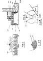
- the figures represent the gas molecule diffractor according to the invention intended for internal combustion engines (not shown) or the like. It comprises an external frame 10 having a central and longitudinal channel 11.
- the frame 10 which can be made in any suitable manner with the most suitable material. It comprises a cylindrical part 12 which has an open end 13 and a second end comprising lugs 14 and 14a, intended for fixing on the one hand to the intake manifold and on the other hand to the carburetor at the top by through the ears 15 and 15 a.
- the ears have holes 16 - 16a, 17 - 17a, which allow the junction with the carburetor or the injection system tion on the one hand and the intake manifold or cylinder head on the other hand.
- the internal peripheral surface of the frame 10 has at its lower part a circular part 18-18a, having a venturi structure, that is to say a part converging towards the inside of the frame, on the upper face side, and a diverging part on the face side lower.
- This part is intended in addition to its dynamic function to block the position of the structure of the diffractor 19.
- the structure of the diffractor 19 according to the invention represented by FIGS. 1-2-3, has at its upper part elements 20 of triangular shapes with vertices converging towards the center of the diffractor, each triangle present at its base and according to the radius of the circle of the diffractor, a groove 21, or transfer channel, which passes right through by dividing the base into two small triangles 22 - 22 a, having in turn a small groove 23 at their base.
- the grooves could possibly be replaced by close cylindrical holes or ovoid bores or of any shape whatsoever.
- the structure of the diffractor can be imagined integral with the frame by the base of the triangular elements and the top of the triangles of which would then no longer be integral.
- the surface of the diffractor has a roof top.
- the surface of the diffractor has grooves, or transfer channels, on its top 25 along the radius of the diffractor and in the axis of each transverse groove 21, an axis passing through the middle of the base of each triangle 20.
- the lateral structure of the "diffractor according to the invention represented by FIGS. 1-3-4 presents wells 26 of suitable shapes, one or more superimposed whose axis corresponds to the radius of the diffraction structure and perpendicular or oblique with respect to to the direction of flow of the gas stream.
- the structure of the resonance chamber 27 according to the drawback shown in FIGS. 1 and 4 is characterized by an empty space containing in its center a junction pin 28 spacer which advantageously makes it possible to create a zone of turbulence.
- the structure of the second diffraction stage 29 according to the invention tion represented by Figures 1-2-4- presents elements of triangular shape 31 whose upper part can be striated or not had the same title as the surface of the first diffraction stage.
- the grooves can be replaced by conduits of variable shapes whose axis is that of the axis of the entire diffraction structure but can also be different from this axis.
- the grooves 32 are parallel to the axis of the assembly or can be oblique and along the radius of the body of the structure.
- the lateral part of the second diffraction stage has cylindrical wells 26 whose axis corresponds to the radius of the structure
- the structure of the third diffraction stage according to the invention represented by FIGS. 1 and 4 has a cylindrical assembly integral with the frame 10, an assembly consisting of a conver gent 34 reducing the channel and a digergent 35 restoring the diameter identical to the one before the strangulation.
- cylindrical channels 36 In the convex part 18 of the structure I strangulation of the ven turi, are located cylindrical channels 36 whose axis is either parallel to the body of the frame, or slightly oblique, but which make the converging part communicate with the diverging part.
- the flow of the gas mixture coming from the carburetor supply system 37 or injection system passes through the first diffraction stage, to reach the resonance chamber, passes through the second diffraction stage to be accelerated by the 'stage of the venturi before entering the intake manifold 38.
Landscapes
- Engineering & Computer Science (AREA)
- Chemical & Material Sciences (AREA)
- Combustion & Propulsion (AREA)
- Mechanical Engineering (AREA)
- General Engineering & Computer Science (AREA)
- Physical Or Chemical Processes And Apparatus (AREA)
Applications Claiming Priority (2)
| Application Number | Priority Date | Filing Date | Title |
|---|---|---|---|
| FR8317430A FR2554171A1 (fr) | 1983-10-27 | 1983-10-27 | Diffracteur de molecules gazeuses pour moteur a combustion interne |
| FR8317430 | 1983-10-27 |
Publications (1)
| Publication Number | Publication Date |
|---|---|
| EP0139603A1 true EP0139603A1 (de) | 1985-05-02 |
Family
ID=9293716
Family Applications (1)
| Application Number | Title | Priority Date | Filing Date |
|---|---|---|---|
| EP84450023A Withdrawn EP0139603A1 (de) | 1983-10-27 | 1984-10-24 | Molekülbrecher und seine Verwendung für die Gemischzufuhr bei Brennkraftmaschinen |
Country Status (4)
| Country | Link |
|---|---|
| EP (1) | EP0139603A1 (de) |
| AU (1) | AU3558184A (de) |
| FR (1) | FR2554171A1 (de) |
| WO (1) | WO1985001990A1 (de) |
Families Citing this family (1)
| Publication number | Priority date | Publication date | Assignee | Title |
|---|---|---|---|---|
| RU2144999C1 (ru) * | 1995-08-25 | 2000-01-27 | Драгомиров Сергей Григорьевич | Смесеобразующее устройство для бензинового двигателя внутреннего сгорания |
Citations (3)
| Publication number | Priority date | Publication date | Assignee | Title |
|---|---|---|---|---|
| FR627390A (fr) * | 1926-08-31 | 1927-10-03 | Brasseur économiseur d'essence | |
| FR788166A (fr) * | 1934-07-04 | 1935-10-05 | Perfectionnements aux dispositifs de pulvérisation pour améliorer le mélange gazeux sortant d'un carburateur | |
| US2721791A (en) * | 1951-11-10 | 1955-10-25 | William J Linn | Liquid fuel atomizers with diffuser means |
-
1983
- 1983-10-27 FR FR8317430A patent/FR2554171A1/fr not_active Withdrawn
-
1984
- 1984-10-24 EP EP84450023A patent/EP0139603A1/de not_active Withdrawn
- 1984-10-24 WO PCT/FR1984/000243 patent/WO1985001990A1/fr not_active Ceased
- 1984-10-24 AU AU35581/84A patent/AU3558184A/en not_active Abandoned
Patent Citations (3)
| Publication number | Priority date | Publication date | Assignee | Title |
|---|---|---|---|---|
| FR627390A (fr) * | 1926-08-31 | 1927-10-03 | Brasseur économiseur d'essence | |
| FR788166A (fr) * | 1934-07-04 | 1935-10-05 | Perfectionnements aux dispositifs de pulvérisation pour améliorer le mélange gazeux sortant d'un carburateur | |
| US2721791A (en) * | 1951-11-10 | 1955-10-25 | William J Linn | Liquid fuel atomizers with diffuser means |
Also Published As
| Publication number | Publication date |
|---|---|
| AU3558184A (en) | 1985-05-22 |
| WO1985001990A1 (fr) | 1985-05-09 |
| FR2554171A1 (fr) | 1985-05-03 |
Similar Documents
| Publication | Publication Date | Title |
|---|---|---|
| EP0793010B1 (de) | Brennstoffeinspritzeinrichtung für ein Staustrahltriebwerk | |
| FR2967239A1 (fr) | Jets auto-oscillants d'injection de combustible | |
| EP0239462A1 (de) | Brennstoffeinspritzeinrichtung mit axial-centripetaler Luftzuführung | |
| EP1387986A1 (de) | Vorrichtung und verfahren zum einspritzen von flüssigkraftstoff in einen luftstrom für eine brennkammer | |
| FR2663083A1 (fr) | Dispositif de tourbillonnement pour moteur a combustion interne. | |
| FR3110634A1 (fr) | Dispositif de mélange, ligne d’échappement et véhicule associés | |
| EP0099828B1 (de) | Vorrichtung zur Verbrennung von brennbaren Fluiden mit Luftinduktion | |
| CA2634615C (fr) | Chambre de combustion de turbomachine a circulation helicoidale de l'air | |
| FR2774152A1 (fr) | Chambre de combustion de turbine a gaz fonctionnant au carburant liquide | |
| EP2126299A1 (de) | Abgasstrecke für verbrennungsmotor mit vorrichtung zur reduktion von stickstoffoxiden | |
| EP0139603A1 (de) | Molekülbrecher und seine Verwendung für die Gemischzufuhr bei Brennkraftmaschinen | |
| EP0189715A1 (de) | Vorrichtung zum Kontrollieren des von einem pneumatischen Einspritzsystem gelieferten Gemischstrahls | |
| FR2602271A1 (fr) | Dispositif d'injection, pour turbomachines, a vrille de turbulence a calage variable | |
| FR2665729A1 (fr) | Dispositif d'injection de carburant pour une chambre de combustion de turbomachine. | |
| FR2495221A1 (fr) | Structure de conduit d'admission pour moteurs a combustion interne | |
| FR2549897A1 (fr) | Dispositif d'admission pour moteur a combustion interne | |
| FR2921119A1 (fr) | Fusee statoreacteur | |
| WO1988007626A1 (fr) | Dispositif d'evaporation et d'homogeneisation d'un melange par exemple pour moteur a combustion interne | |
| WO2008034982A1 (fr) | Agencement pour la depollution d'un moteur thermique comportant un conduit muni d'un element en saillie | |
| FR2524072A1 (fr) | Carburateur a venturi variable | |
| FR2555253A1 (fr) | Dispositif de diffusion par diffraction d'un melange air-essence et son utilisation pour l'alimentation d'un moteur a combustion interne | |
| FR2493404A1 (fr) | Dispositif d'homogeneisation du melange aspire par un moteur a combustion interne | |
| FR2945836A1 (fr) | Dispositif a effet tourbillonnaire de gaz pour turbocompresseur | |
| FR3156508A1 (fr) | Chambre de combustion annulaire pour turbine à gaz bas-carbone. | |
| FR2856114A1 (fr) | Injecteur pour moteur a combustion interne a faible taux de polluants |
Legal Events
| Date | Code | Title | Description |
|---|---|---|---|
| PUAI | Public reference made under article 153(3) epc to a published international application that has entered the european phase |
Free format text: ORIGINAL CODE: 0009012 |
|
| AK | Designated contracting states |
Designated state(s): AT BE CH DE FR GB IT LI LU NL SE |
|
| RTI1 | Title (correction) | ||
| STAA | Information on the status of an ep patent application or granted ep patent |
Free format text: STATUS: THE APPLICATION IS DEEMED TO BE WITHDRAWN |
|
| 18D | Application deemed to be withdrawn |
Effective date: 19860404 |