EP0139719B1 - Automatische Zu- und Ablaufventilanordnung - Google Patents
Automatische Zu- und Ablaufventilanordnung Download PDFInfo
- Publication number
- EP0139719B1 EP0139719B1 EP84901654A EP84901654A EP0139719B1 EP 0139719 B1 EP0139719 B1 EP 0139719B1 EP 84901654 A EP84901654 A EP 84901654A EP 84901654 A EP84901654 A EP 84901654A EP 0139719 B1 EP0139719 B1 EP 0139719B1
- Authority
- EP
- European Patent Office
- Prior art keywords
- valve
- load
- port
- pump
- valving
- Prior art date
- Legal status (The legal status is an assumption and is not a legal conclusion. Google has not performed a legal analysis and makes no representation as to the accuracy of the status listed.)
- Expired
Links
- 239000012530 fluid Substances 0.000 claims description 21
- 230000013011 mating Effects 0.000 claims description 8
- 230000002457 bidirectional effect Effects 0.000 claims description 5
- 238000010276 construction Methods 0.000 description 10
- 238000006073 displacement reaction Methods 0.000 description 6
- 238000000926 separation method Methods 0.000 description 4
- 230000008901 benefit Effects 0.000 description 3
- 230000004044 response Effects 0.000 description 3
- 230000009471 action Effects 0.000 description 2
- 230000000875 corresponding effect Effects 0.000 description 2
- 230000001419 dependent effect Effects 0.000 description 2
- 230000000694 effects Effects 0.000 description 2
- 238000000034 method Methods 0.000 description 2
- 238000004886 process control Methods 0.000 description 2
- 230000035945 sensitivity Effects 0.000 description 2
- 230000000712 assembly Effects 0.000 description 1
- 238000000429 assembly Methods 0.000 description 1
- 230000004888 barrier function Effects 0.000 description 1
- 238000004891 communication Methods 0.000 description 1
- 230000000295 complement effect Effects 0.000 description 1
- 230000001276 controlling effect Effects 0.000 description 1
- 230000002079 cooperative effect Effects 0.000 description 1
- 230000007423 decrease Effects 0.000 description 1
- 238000010586 diagram Methods 0.000 description 1
- 238000007667 floating Methods 0.000 description 1
- 238000012423 maintenance Methods 0.000 description 1
- 239000003208 petroleum Substances 0.000 description 1
- 230000008569 process Effects 0.000 description 1
- 238000005086 pumping Methods 0.000 description 1
- 238000007789 sealing Methods 0.000 description 1
- 239000000126 substance Substances 0.000 description 1
Images


Classifications
-
- F—MECHANICAL ENGINEERING; LIGHTING; HEATING; WEAPONS; BLASTING
- F15—FLUID-PRESSURE ACTUATORS; HYDRAULICS OR PNEUMATICS IN GENERAL
- F15B—SYSTEMS ACTING BY MEANS OF FLUIDS IN GENERAL; FLUID-PRESSURE ACTUATORS, e.g. SERVOMOTORS; DETAILS OF FLUID-PRESSURE SYSTEMS, NOT OTHERWISE PROVIDED FOR
- F15B13/00—Details of servomotor systems ; Valves for servomotor systems
- F15B13/01—Locking-valves or other detent i.e. load-holding devices
-
- F—MECHANICAL ENGINEERING; LIGHTING; HEATING; WEAPONS; BLASTING
- F15—FLUID-PRESSURE ACTUATORS; HYDRAULICS OR PNEUMATICS IN GENERAL
- F15B—SYSTEMS ACTING BY MEANS OF FLUIDS IN GENERAL; FLUID-PRESSURE ACTUATORS, e.g. SERVOMOTORS; DETAILS OF FLUID-PRESSURE SYSTEMS, NOT OTHERWISE PROVIDED FOR
- F15B11/00—Servomotor systems without provision for follow-up action; Circuits therefor
- F15B11/08—Servomotor systems without provision for follow-up action; Circuits therefor with only one servomotor
-
- F—MECHANICAL ENGINEERING; LIGHTING; HEATING; WEAPONS; BLASTING
- F15—FLUID-PRESSURE ACTUATORS; HYDRAULICS OR PNEUMATICS IN GENERAL
- F15B—SYSTEMS ACTING BY MEANS OF FLUIDS IN GENERAL; FLUID-PRESSURE ACTUATORS, e.g. SERVOMOTORS; DETAILS OF FLUID-PRESSURE SYSTEMS, NOT OTHERWISE PROVIDED FOR
- F15B2211/00—Circuits for servomotor systems
- F15B2211/20—Fluid pressure source, e.g. accumulator or variable axial piston pump
- F15B2211/205—Systems with pumps
- F15B2211/2053—Type of pump
- F15B2211/20561—Type of pump reversible
-
- F—MECHANICAL ENGINEERING; LIGHTING; HEATING; WEAPONS; BLASTING
- F15—FLUID-PRESSURE ACTUATORS; HYDRAULICS OR PNEUMATICS IN GENERAL
- F15B—SYSTEMS ACTING BY MEANS OF FLUIDS IN GENERAL; FLUID-PRESSURE ACTUATORS, e.g. SERVOMOTORS; DETAILS OF FLUID-PRESSURE SYSTEMS, NOT OTHERWISE PROVIDED FOR
- F15B2211/00—Circuits for servomotor systems
- F15B2211/20—Fluid pressure source, e.g. accumulator or variable axial piston pump
- F15B2211/27—Directional control by means of the pressure source
-
- F—MECHANICAL ENGINEERING; LIGHTING; HEATING; WEAPONS; BLASTING
- F15—FLUID-PRESSURE ACTUATORS; HYDRAULICS OR PNEUMATICS IN GENERAL
- F15B—SYSTEMS ACTING BY MEANS OF FLUIDS IN GENERAL; FLUID-PRESSURE ACTUATORS, e.g. SERVOMOTORS; DETAILS OF FLUID-PRESSURE SYSTEMS, NOT OTHERWISE PROVIDED FOR
- F15B2211/00—Circuits for servomotor systems
- F15B2211/40—Flow control
- F15B2211/405—Flow control characterised by the type of flow control means or valve
- F15B2211/40515—Flow control characterised by the type of flow control means or valve with variable throttles or orifices
-
- F—MECHANICAL ENGINEERING; LIGHTING; HEATING; WEAPONS; BLASTING
- F15—FLUID-PRESSURE ACTUATORS; HYDRAULICS OR PNEUMATICS IN GENERAL
- F15B—SYSTEMS ACTING BY MEANS OF FLUIDS IN GENERAL; FLUID-PRESSURE ACTUATORS, e.g. SERVOMOTORS; DETAILS OF FLUID-PRESSURE SYSTEMS, NOT OTHERWISE PROVIDED FOR
- F15B2211/00—Circuits for servomotor systems
- F15B2211/40—Flow control
- F15B2211/415—Flow control characterised by the connections of the flow control means in the circuit
- F15B2211/41581—Flow control characterised by the connections of the flow control means in the circuit being connected to an output member and a return line
-
- F—MECHANICAL ENGINEERING; LIGHTING; HEATING; WEAPONS; BLASTING
- F15—FLUID-PRESSURE ACTUATORS; HYDRAULICS OR PNEUMATICS IN GENERAL
- F15B—SYSTEMS ACTING BY MEANS OF FLUIDS IN GENERAL; FLUID-PRESSURE ACTUATORS, e.g. SERVOMOTORS; DETAILS OF FLUID-PRESSURE SYSTEMS, NOT OTHERWISE PROVIDED FOR
- F15B2211/00—Circuits for servomotor systems
- F15B2211/40—Flow control
- F15B2211/42—Flow control characterised by the type of actuation
- F15B2211/428—Flow control characterised by the type of actuation actuated by fluid pressure
-
- F—MECHANICAL ENGINEERING; LIGHTING; HEATING; WEAPONS; BLASTING
- F15—FLUID-PRESSURE ACTUATORS; HYDRAULICS OR PNEUMATICS IN GENERAL
- F15B—SYSTEMS ACTING BY MEANS OF FLUIDS IN GENERAL; FLUID-PRESSURE ACTUATORS, e.g. SERVOMOTORS; DETAILS OF FLUID-PRESSURE SYSTEMS, NOT OTHERWISE PROVIDED FOR
- F15B2211/00—Circuits for servomotor systems
- F15B2211/70—Output members, e.g. hydraulic motors or cylinders or control therefor
- F15B2211/705—Output members, e.g. hydraulic motors or cylinders or control therefor characterised by the type of output members or actuators
- F15B2211/7051—Linear output members
- F15B2211/7052—Single-acting output members
-
- F—MECHANICAL ENGINEERING; LIGHTING; HEATING; WEAPONS; BLASTING
- F15—FLUID-PRESSURE ACTUATORS; HYDRAULICS OR PNEUMATICS IN GENERAL
- F15B—SYSTEMS ACTING BY MEANS OF FLUIDS IN GENERAL; FLUID-PRESSURE ACTUATORS, e.g. SERVOMOTORS; DETAILS OF FLUID-PRESSURE SYSTEMS, NOT OTHERWISE PROVIDED FOR
- F15B2211/00—Circuits for servomotor systems
- F15B2211/70—Output members, e.g. hydraulic motors or cylinders or control therefor
- F15B2211/705—Output members, e.g. hydraulic motors or cylinders or control therefor characterised by the type of output members or actuators
- F15B2211/7051—Linear output members
- F15B2211/7053—Double-acting output members
Definitions
- the present invention relates to an automatic supply and exhaust valve assembly comprising at least one control valve comprising a tubular element having a source port, a load port and at least one drain port and further comprising a reciprocative valve member, with said tubular element and said valve member having axially spaced first and second mating pairs of valving surfaces which are mechanically coupled and arranged for connecting said source port with said load port as fluid pressure supplied to the source port exceeds pressure at the load port and for connecting said load port with said drain port so as to relieve pressure at said load port.
- a valve assembly and, more specifically, an automatic supply and exhaust valve of this general type is known from US-A-2 702 044.
- the known valve comprises oppositely directed pairs of valving surfaces, one of which is closed while the other is open and vice versa, so that the load port being arranged intermediate said source and drain ports is either in fluid connection with the source port or with the drain port.
- automated valve refers to the fact that any device being connected to the load port, especially the air brakes of a truck, are automatically vented via the drain port as soon as the pressure at the source port decreases below a predetermined value at which the source port is closed.
- valve assemblies such as described in GB-A-597 103 and FR-A-2 298 043 comprise reciprocative valve members for opening and closing in synchronism fluid connections between one single source port and two separate load ports. These valves are serving the purpose of subdividing an inlet fluid stream at the source port into two equal outlet fluid streams at the load ports.
- large process control valves e.g. such as those employed in petroleum refineries and chemical and power plants are often driven by electrically controllable, hydraulic positioning systems.
- hydraulic positioning systems commonly includes a powerful, single-acting, spring-return hydraulic piston and a constant speed positive displacement pump which provides a source of hydraulic power, both for stroking the piston and for holding same at any selected position within its stroke.
- the pump is run continuously and the pressure to the actuator is modulated by a conventional three way servo valve or equivalent systems means such as a flapper nozzle or, jet pipe system which relieves excess pressure to the sump.
- the servo valve is responsive to an electrical command signal employed in conjunction with a position feedback loop.
- the servo valve throttles the pump output in order to create the proper back pressure as required to hold the piston in position and the totality of the flow is returned to the pump sump when the piston is immobile.
- the efficiency of present state-of-the- art hydraulic actuators system is, in the large majority of applications, in the order of five percent or less. Inherently a majority of the hydraulic energy generated by the pump is wasted as heat while the actuator is immobile at any intermediate position.
- the actuator is, in fact, immobile much of the time in most valve applications, particularly in large and rather stable processes. Not only is the loss of energy wasteful, the heat created is itself troublesome.
- an object of the present invention to provide an improved valve assembly, especially a reciprocative check valve which selectively allows free flow through a single line port in either direction in order to selectively fill or unfill a variable volume load, e.g. to extend or retract the piston of a single-acting, spring-return actuator.
- This object according to the invention is accomplished by means of an automatic supply and exhaust valve assembly of the type indicated at the outlet and being characterized in that said pairs of valving surfaces are arranged to open and close in synchronism, and that said drain port is provided in said tubular element at a position intermediate said source and load ports so as to allow for simultaneous matching flows from both said load port and said source port to said at least one drain port when said valving surfaces are open and so as to be disconnected from said source and load ports when said valving surfaces are closed.
- a hydraulic system in accordance with one aspect of the present invention employs a pump which draws fluid from a pump to provide fluid under pressure.
- a reciprocative check valve having first and second mating pairs of valving surfaces which are mechanically coupled and arranged to open in synchronism when the pump pressure exceeds the load pressure.
- These valving surfaces are connected in series between the pump and the load with the connection bezween the two pairs of valving surfaces being connected also, through a release valve, to the sump.
- the reciprocative check valve or flow matching valve is a device employing a tubular body structure having a source port at a first axial position along the body and a load port at a second position along the body which is axially displaced from the first position.
- a drain port is located between the source and load ports.
- the plug member which is movable axially in response to any difference in the pressures at the source and load ports.
- the plug member includes rigidly connected mating surfaces which progressively open the source and load ports in synchronism. When opened, the source and load ports each connect with a drain port.
- a common or separate drain port may be provided depending on the end use application.
- hydraulic actuators operating process control valves typically employ a relatively massive hydraulic prime mover.
- a mover is indicated generally by reference character 11 and comprises a piston 13 and a cylinder 15.
- the piston is normally biased by a heavy spring, as indicated at 17, toward a return position.
- Hydraulic fluid from a sump 19 is provided under pressure suitable for operating prime mover 11 by a unidirectional pump 21 which runs constantly.
- a control valve e.g. an electrically operated, spool type servo valve 25 is provided for modulating the pressure of the fluid as suitable for moving the prime mover piston or holding it at any position within the stroke range. The excess flow is returned to the pump sump 19 through line 28.
- valve illustrated there comprises a generally cylindrical or tubular body portion 33 within which operates a plug member 35.
- the overall control valve structure is designated by reference character 31.
- the valve body 33 provides a first valve seat 37 and a second valve seat 39 which is axially displaced along the body from the first valve seat. Both valve seats face in the same direction and are of the same diameter.
- the plug member 35 includes a first valving surface 41 and a second valving surface 43 which mate with the seats 37 and 39 respectfully.
- the axial displacement between the valving surfaces 41 and 43 matches the axial spacing of the seats 37 and 39 so that the two ports open synchroni- ously.
- the port controlled by the valving surface 41 in cooperation with the seat 37 may be considered the source or supply port while the port controlled by the second valving surface 43 in conjunction with the second valve seat 39 may be considered the load port.
- the plug member 35 is preferably lightly biased in the direction tending to close the ports, e.g. by a spring 45, the plug member is essentially floating in the body so as to be responsive to any difference in pressure between the supply side and the load side.
- valve body 33 and plug member 35 provide, between them, an intermediate chamber 47.
- a drain port opens into chamber 47, as indicated at reference character 49. While the valve body 33 and plug member 35 are illustrated as integral structures for the purpose of explanation, it will be understood by those skilled in the mechanical arts that these parts are necessarily assembled of multiple components so as to permit the construction of interlocking assembly shown in the drawings.
- the valve 31 of Figure 2 is functional to provide flow matching characteristics and, in effect, reciprocative check valving. This operation may best be understood in conjunction with the description of an overall system, such as that illustrated in Figure 3.
- the control valve of Figure 2 is installed in the supply line 24.
- the return line 28 is also connected to the drain port of the valve 31.
- a simple two way directional valve e.g. a solenoid operated on-off valve, designated by reference character 51.
- a simple on/off valve for unfilling the cylinder is possible since the single control valve 25 is functional during both filling and emptying of the pcston 13.
- the drain port 49 must be opened i.e., by opening the on/off valve 51. However, the mere opening of this value will not permit the piston to retract if the servo valve is not delivering pressure to the source port. If, though, the servo valve is then operated so that a hydraulic flow is introduced into the source port of the control valve 31 while its drain port is open, it can be seen that this flow will return back to the sump as soon as the source pressure equals the load pressure and moves the plug member 35 sufficiently to open the source port.
- the load port is also opened by the same amount as the source port.
- the valving surface in the two ports are of equal diameter and, therefore, of equal area.
- the control valve 31 operates as a flow matching device, that is, the flow out of the piston will be equal to the flow- into the source port of the control value 31. As in the filling mode, this flow is controllable by means of the throttling valve 25.
- the control valve 31 also operates as a check valve with respect to the return line 30 since, even if the solenoid valve is open and the pump pressure drops below the load pressure, no back flow will take place.
- valves 51 and 25 can be combined in a single spool valve type structure.
- sleeve 63 Fitting within an overall body assembly 61 is a sleeve 63 and a piston 65.
- Sleeve 65 is stationary within the body member 61 while the piston 65 is slidable axially within the sleeve 63, i.e. similar to the manner in which the spool element in a spool valve is slidable.
- the piston is lapped to the sleeve to provide a close, low leakage fit.
- the sleeve 63 is provided with a pair of internal annular grooves 67 and 69 with a precise axial separation between them.
- the piston 65 is provided with a matching pair of external annular grooves 71 and 73 wth an axial separation between these grooves which matches the axial separation between the grooves 67 and 69 on the sleeve.
- a first passageway system 70 connects the groove 71 with the source port while a second passageway system 77 provides communication from the groove 73 to the load port end of the sleeve 63.
- Cross ports 78 and 79 in the sleeve connect the grooves 67 and 69, to a respective pair of drain ports 82 and 84 in the valve body 61.
- the drain ports 82 and 84 are connected together externally of the body 61 to form a common drain functioning in the same manner as the single drain of the sample valve of Figure 2.
- a pressure barrier i.e. a sealed land
- the upper end of the sleeve 63 provides a valve seat, as indicated by reference character 85 and a spherical valving element 87 is lightly biased into contact with this seat by a spring 89.
- a projecting portion 91 of the piston 65 is formed to lift the valving element 87 from the seat 85 just as the annular grooves on the piston come adjacent the respective annular grooves on the sleeve 63.
- valve device of Figure 4 Since the overall operation of the valve device of Figure 4 in the system of Figure 3 is basically the same as that of the valve device of Figure 2, it will also be seen that the valve device of Figure 4 may be directly substituted in the novel hydraulic system of Figure 3 which will continue to provide the desired function and advantages.
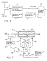
- a bidirectional positive displacement pump 100 is utilized for providing hydraulic fluid under a pressure suitable for operating a cylinder, again indicated by reference character 15.
- a pressurized accumulator 101 provides a reservoir of hydraulic fluid. This reservoir is connected, through respective check valves 102 and 103, to both sides of pump 100.
- Pump 100 is preferably of the positive displacement, meshing gear type and is driven in either direction by a stepping motor 105. Movement of the piston 13 is tracked by a suitable transducer e.g. a side wire potentiometer as indicated at 106, so as to provide a suitable feedback signal or voltage.
- a pressure release valve is provided, as indicated by reference character 108, for limiting the maximum pressure which can be applied to the cylinder 15.
- the cylinder 15 is connected, through a check valve 109, to one side of the pump and, through a flow matching control valve 31, to the other side of the pump.
- the feedback signal obtained from the potentiometer 106 is compared, in a differential amplifier 111, with a reference voltage representing the desired position of the piston thereby to generate an error signal representing the difference between the desired and actual positions for the piston.
- a zero crossing detector circuit 113 provides a signal indicating the sense or polarity of the error and this signal is provided to the direction control input of a conventional stepper motor driving circuit, indicated by reference character 115.
- a signal proportional to the amplitude of the error, independent of polarity, is provided by an absolute value detector circuit, indicated by reference character 117. As is understood, this circuitry may be constituted by a simple array of diodes.
- the signal proportional to the absolute value of the error is provided to enable a voltage-to-frequency converter circuit 119 whose output is, in turn, applied to the step signal input of the stepper motor driving circuit 115.
- the stepper motor 105 will be energized in a direction which reverses in accordance with the sensed direction of the error and at a speed which is proportional to the magnitude of the error. This operation thus closes the servo-loop so that the position of the piston will follow variations in the set point reference signal, as desired.
- the stepper motor 105 is energized only when an error exists and the level of energization is proportional to the error. In relatively stable overall systems therefore, the motor is energized only intermittently.
- this intermittent energi- . zation only when needed both reduces the average power requirement and the amount of heat dissipated in the system.
- the position of the piston 13 is maintained by positive acting check valve structures and is not a function of the leakage or backflow which would occur through the pump 19 if the load pressure were maintained across the pump itself.
- all of the valves in the system are essentially simple check valve constructions and no elaborate reversing or four- way valves are required, as would typically be the case in conventional hydraulic servo control systems.
- a prime mover is indicated generally by reference character 121 and comprises piston 123 and cylinder 125.
- the double rod ended piston provides equal annular area on both faces of tiie piston.
- a bi-directional, positive displacement pump 127 is utilized for providing hydraulic fluid under a pressure suitable for operating the cylinder.
- a pressurized accumulator 131 provides a reservoir for the hydraulic fluid. This reservoir is connected through respective check valves 132 and 133 to both sides of the pump 127.
- Pump 127 is preferably of the positive displacement meshing gear type and is driven in either direction by a stepper motor 135 whose speed can be varied from zero to a maximum by means of suitable control electronics 137. Movement of the piston is tracked by a suitable transducer; e.g., a slide wire potentiometer indicated at 138 so as to provide a suitable feedback voltage or signal.
- One side of the pump is connected to one side of the cylinder 121 through a hydraulic circuit which includes the source/source-drain path of a flow matching valve 139 and a check valve 147.
- the other side of the pump 127 is symmetrically connected through a hydraulic circuit which includes the source/source-drain path of a flow matching valve 141 and a check valve 145.
- Both flow matching valves 139 and 141 are identical in construction and size. The construction is preferably that illustrated in Figure 4 with separate drain ports being maintained for the source and load ports.
- Each side of the cylinder 121 is also cross connected to the load port of the opposite flow matching valve 139 or 141.
- the load- drain port of each of the flow matching valves is cross connected to the source port of the other flow matching valve.
- the pump 127 In order to drive the piston against the load, the pump 127 is driven so as to produce a flow from left to right as seen in the drawings.
- initial opening of the paths through the flow matching valve 139 will occur and the pressure at the outlet side of the pump will then equalize with the high pressure side of the cylinder.
- flow Under continued pumping, flow will then occur through the source/ source-drain path of the valve 139 and the check valve 147, driving the piston to the left.
- an equal flow will return from the left side of the piston through the load/load-drain path of the control valve 139 to the low pressure side of the pump in a relatively straightforward manner.
- the load is aiding the motion and the pump 127 may be considered to be in an overrunning condition where the intake pressure may tend to exceed that on the low pressure side of the cylinder.
- the other, normally passive, flow matching valve 139 may open slightly. The opening of the load drain/load path will bypass some of the pump's output allowing a partial reclosing of the flow matching valve 141 which therefore increases the restriction and reduces the flow from the high pressure side of the cylinder, thereby restoring balance.
- the motor is energized only intermittently. As is understood, this both reduces the average power requirement and the amount of heat dissipated in the system. Furthermore, when the motor is not energized, the piston position is maintained by positive acting check valve structures and is not a function of the leakage or back flow which would occur through the pump if a load pressure were maintained across the pump itself. It may also be pointed out that all of the valves in this system, other than flow matching valves 139 and 141, are essentially simple check valve construction and no elaborate reversing four way valves, or counter balancing valves are required as would be the case in conventional hydraulic actuators.
Landscapes
- Engineering & Computer Science (AREA)
- Physics & Mathematics (AREA)
- Fluid Mechanics (AREA)
- Mechanical Engineering (AREA)
- General Engineering & Computer Science (AREA)
- Fluid-Pressure Circuits (AREA)
Claims (8)
Applications Claiming Priority (4)
| Application Number | Priority Date | Filing Date | Title |
|---|---|---|---|
| US06/479,672 US4557180A (en) | 1983-03-28 | 1983-03-28 | Control valve and hydraulic system employing same |
| US479673 | 1983-03-28 | ||
| US479672 | 1983-03-28 | ||
| US06/479,673 US4625513A (en) | 1983-03-28 | 1983-03-28 | Controlled flow hydraulic system |
Publications (3)
| Publication Number | Publication Date |
|---|---|
| EP0139719A1 EP0139719A1 (de) | 1985-05-08 |
| EP0139719A4 EP0139719A4 (de) | 1986-07-17 |
| EP0139719B1 true EP0139719B1 (de) | 1989-07-05 |
Family
ID=27046318
Family Applications (1)
| Application Number | Title | Priority Date | Filing Date |
|---|---|---|---|
| EP84901654A Expired EP0139719B1 (de) | 1983-03-28 | 1984-03-22 | Automatische Zu- und Ablaufventilanordnung |
Country Status (3)
| Country | Link |
|---|---|
| EP (1) | EP0139719B1 (de) |
| DE (1) | DE3478869D1 (de) |
| WO (1) | WO1984003916A1 (de) |
Families Citing this family (3)
| Publication number | Priority date | Publication date | Assignee | Title |
|---|---|---|---|---|
| US5072648A (en) * | 1990-06-04 | 1991-12-17 | Caterpillar Industrial Inc. | Control system for a fluid operated jack |
| GB9603894D0 (en) * | 1996-02-23 | 1996-04-24 | Smiths Industries Plc | Hydraulic systems and valve assemblies |
| CN116658471A (zh) * | 2023-06-08 | 2023-08-29 | 阳春新钢铁有限责任公司 | 一种双高线立活套气缸阀台的快速切换装置及使用方法 |
Family Cites Families (10)
| Publication number | Priority date | Publication date | Assignee | Title |
|---|---|---|---|---|
| GB597103A (en) * | 1945-08-09 | 1948-01-19 | Heywood Compressor Company Ltd | Improvements in double beat or equilibrium valves |
| US2646025A (en) * | 1951-02-07 | 1953-07-21 | Bendix Aviat Corp | By-pass valve for hydraulic motors |
| US2702044A (en) * | 1953-11-23 | 1955-02-15 | Albert D Johnston | Automatic supply and exhaust valve |
| US2858840A (en) * | 1955-09-12 | 1958-11-04 | Worthington Corp | Snap-acting pneumatic relays |
| US3355994A (en) * | 1966-01-13 | 1967-12-05 | New York Air Brake Co | Hydraulic system |
| US3492052A (en) * | 1968-10-28 | 1970-01-27 | Berg Mfg & Sales Co | Front axle valve |
| US3638530A (en) * | 1969-09-04 | 1972-02-01 | Jackson Products Co | Hydraulic counterweight |
| FR2298043A1 (fr) * | 1975-01-14 | 1976-08-13 | Rauline Maurice | Mini-vanne a clapets flottants pour fluides sous pression |
| US3943824A (en) * | 1975-01-22 | 1976-03-16 | Deere & Company | Hydraulic system |
| US4278010A (en) * | 1979-07-23 | 1981-07-14 | United Technologies Corporation | Fluid flow regulator valve |
-
1984
- 1984-03-22 EP EP84901654A patent/EP0139719B1/de not_active Expired
- 1984-03-22 DE DE8484901654T patent/DE3478869D1/de not_active Expired
- 1984-03-22 WO PCT/US1984/000448 patent/WO1984003916A1/en not_active Ceased
Also Published As
| Publication number | Publication date |
|---|---|
| EP0139719A1 (de) | 1985-05-08 |
| WO1984003916A1 (en) | 1984-10-11 |
| EP0139719A4 (de) | 1986-07-17 |
| DE3478869D1 (en) | 1989-08-10 |
Similar Documents
| Publication | Publication Date | Title |
|---|---|---|
| US4696163A (en) | Control valve and hydraulic system employing same | |
| US4625513A (en) | Controlled flow hydraulic system | |
| US4557180A (en) | Control valve and hydraulic system employing same | |
| US4456434A (en) | Power transmission | |
| EP1186783B1 (de) | Hydrauliksystem mit gekreuzter Energierückgewinnung | |
| CA2219207C (en) | Pressure compensating hydraulic control system | |
| US4699571A (en) | Control valve for a variable displacement pump | |
| US3722525A (en) | Fluid switching valve | |
| US3922955A (en) | Fail-fixed servovalve | |
| USRE38355E1 (en) | Electrohydraulic control device for double-acting consumer | |
| US4766728A (en) | Flow matching valve and hydraulic system employing same | |
| KR940703974A (ko) | 포펫 및 스풀형 밸브를 구비한 유압 제어 시스템(hydraulic control system having poppet and spool type valves) | |
| US3854382A (en) | Hydraulic actuator controls | |
| US11092173B2 (en) | Flow control for an actuator | |
| EP0224478B1 (de) | Lastfühlerschaltung eines lastabhängigen richtungsregelungsventils | |
| US3772889A (en) | Servo pump having throttled input | |
| US4437388A (en) | Dual input pressure compensated fluid control valve | |
| US5562125A (en) | Two stage electrohydraulic pressure control valve | |
| US5791143A (en) | Flow control valve and hydraulic system employing same | |
| US5799485A (en) | Electrohydraulic control device for double-acting consumer | |
| US4278010A (en) | Fluid flow regulator valve | |
| WO1984003916A1 (en) | Control valve and hydraulic system employing same | |
| US4265272A (en) | Transient start-up eliminator for pressure piloted valve | |
| CA1247982A (en) | Control valve and hydraulic system employing same | |
| JPS5943679B2 (ja) | サアツカンチベン |
Legal Events
| Date | Code | Title | Description |
|---|---|---|---|
| PUAI | Public reference made under article 153(3) epc to a published international application that has entered the european phase |
Free format text: ORIGINAL CODE: 0009012 |
|
| AK | Designated contracting states |
Designated state(s): DE FR GB |
|
| 17P | Request for examination filed |
Effective date: 19850329 |
|
| A4 | Supplementary search report drawn up and despatched |
Effective date: 19860717 |
|
| 17Q | First examination report despatched |
Effective date: 19870507 |
|
| GRAA | (expected) grant |
Free format text: ORIGINAL CODE: 0009210 |
|
| AK | Designated contracting states |
Kind code of ref document: B1 Designated state(s): DE FR GB |
|
| REF | Corresponds to: |
Ref document number: 3478869 Country of ref document: DE Date of ref document: 19890810 |
|
| ET | Fr: translation filed | ||
| REG | Reference to a national code |
Ref country code: GB Ref legal event code: 727 |
|
| REG | Reference to a national code |
Ref country code: GB Ref legal event code: 727A |
|
| PLBE | No opposition filed within time limit |
Free format text: ORIGINAL CODE: 0009261 |
|
| STAA | Information on the status of an ep patent application or granted ep patent |
Free format text: STATUS: NO OPPOSITION FILED WITHIN TIME LIMIT |
|
| 26N | No opposition filed | ||
| REG | Reference to a national code |
Ref country code: GB Ref legal event code: 727B |
|
| REG | Reference to a national code |
Ref country code: GB Ref legal event code: SP |
|
| REG | Reference to a national code |
Ref country code: GB Ref legal event code: IF02 |
|
| PGFP | Annual fee paid to national office [announced via postgrant information from national office to epo] |
Ref country code: FR Payment date: 20030311 Year of fee payment: 20 |
|
| PGFP | Annual fee paid to national office [announced via postgrant information from national office to epo] |
Ref country code: GB Payment date: 20030319 Year of fee payment: 20 |
|
| PGFP | Annual fee paid to national office [announced via postgrant information from national office to epo] |
Ref country code: DE Payment date: 20030414 Year of fee payment: 20 |
|
| PG25 | Lapsed in a contracting state [announced via postgrant information from national office to epo] |
Ref country code: GB Free format text: LAPSE BECAUSE OF EXPIRATION OF PROTECTION Effective date: 20040321 |
|
| REG | Reference to a national code |
Ref country code: GB Ref legal event code: PE20 |