EP0139771A2 - Unité de fermeture de moule pour une machine à mouler par injection des matières plastiques - Google Patents
Unité de fermeture de moule pour une machine à mouler par injection des matières plastiques Download PDFInfo
- Publication number
- EP0139771A2 EP0139771A2 EP83109738A EP83109738A EP0139771A2 EP 0139771 A2 EP0139771 A2 EP 0139771A2 EP 83109738 A EP83109738 A EP 83109738A EP 83109738 A EP83109738 A EP 83109738A EP 0139771 A2 EP0139771 A2 EP 0139771A2
- Authority
- EP
- European Patent Office
- Prior art keywords
- support plate
- piston
- cylinder
- mold
- unit according
- Prior art date
- Legal status (The legal status is an assumption and is not a legal conclusion. Google has not performed a legal analysis and makes no representation as to the accuracy of the status listed.)
- Granted
Links
Images


Classifications
-
- B—PERFORMING OPERATIONS; TRANSPORTING
- B29—WORKING OF PLASTICS; WORKING OF SUBSTANCES IN A PLASTIC STATE IN GENERAL
- B29C—SHAPING OR JOINING OF PLASTICS; SHAPING OF MATERIAL IN A PLASTIC STATE, NOT OTHERWISE PROVIDED FOR; AFTER-TREATMENT OF THE SHAPED PRODUCTS, e.g. REPAIRING
- B29C45/00—Injection moulding, i.e. forcing the required volume of moulding material through a nozzle into a closed mould; Apparatus therefor
- B29C45/17—Component parts, details or accessories; Auxiliary operations
- B29C45/64—Mould opening, closing or clamping devices
- B29C45/67—Mould opening, closing or clamping devices hydraulic
Definitions
- the invention relates to a mold clamping unit according to the preamble of claim 1.
- the free ends of the protruding spars are picked up by an additional support plate, while the rear cylinder ends are gripped by a support plate and are thereby stabilized.
- the cylinder covers of the cylinders slide on the lateral surfaces of the bars. This also necessarily applies to the ring seals embedded in these covers, by means of which the cylinder spaces of the piston-cylinder units are sealed. Since the piston-cylinder units not only open and close the injection mold, but also generate the locking pressure for the injection mold when the plastic material is inserted into the injection mold, the ring seals that seal the high-pressure chambers on the mold side are during their sliding movement, i.e. extremely high pressures up to friction loads subject to approx. 400 bar. Experience has shown that the ring seals mentioned are subject to rapid wear and relatively often. need to be replaced.
- the object of the invention is to develop a mold-closing unit of the type mentioned at the outset in such a way that the sealing members sealing the cylinder spaces of the piston-cylinder units have a substantially longer service life.
- Support plate is formed, on which the stationary cylinders of the piston-cylinder units are centered.
- the piston-cylinder units correspond far more to the respective requirements in terms of the size of the piston surfaces acted upon Press when closing or opening the mold half on the one hand and when building the locking pressure on the other. This is because the piston area acted upon by the locking pressure is considerably larger than the piston area acted upon when the mold is opened or closed.
- the pistons of the piston-cylinder units are expediently seated on sleeves which are fastened to the movable platen and are each slidably mounted on the associated spar. Their length corresponds to the maximum opening or closing stroke (claim 2).
- it has been known per se in injection molding units for over a decade to control the axial stroke of the screw conveyor by means of piston-cylinder units penetrated by spars of the injection molding unit, the pistons of which are indirectly connected to the screw conveyor via necks (DE- PS 20 48 796).
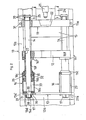
- the movable platen 12 can be moved by means of hydraulic piston-cylinder units 16 on the bars 14 of the four-bar mold clamping unit. These spars are received at one end by the fixed platen 11 and at the other end by a support plate 13. With the plates mentioned, the spars form a guide frame for the movable platen, which rests on the machine base 10 of the plastic injection molding machine.
- the piston-cylinder units 16 that drive the movable platen 12 and also generate the locking pressure for the casting mold 15 are each penetrated by a spar 14 and axially supported on the guide frame.
- the pistons 16b are connected to the movable platen 12 via sleeves 16f, the length of which is designed for a maximum opening stroke of the piston-cylinder units 16.
- the 10a of the machine base walls is fastened by means of screw bolts 31 which penetrate lateral bearing sections 13a 'of the base 13a.
- Each spar 14 is enclosed by a sleeve 16f to form an annular space 26.
- the annular space 26 is delimited on the pouring side by the guide bushing 27. When the mold is closed, the annular space extends axially up to approximately the height of the cylinder space 32, which is used to open the injection mold. casting mold is charged via the connection 36 with hydraulic medium.
- the cylinder space 33 is supplied with pressure oil via the connection 36, via which the high pressure for the locking pressure is also built up.
- the cylinder covers 16d are each supported on an annular shoulder 30 of the associated spar 14 (FIG. 1). They are each pressed onto the associated annular shoulder 30 with the aid of a screw nut 17, which screw nut lies against the support plate 13.
- the cylinder covers 16c on the pouring side are braced with the support plate 13 with the aid of tie rods 29.
- the stationary platen 11 sits on side edges 11a on the edges 10a of the machine base 10 and is fastened there by means of screw bolts 31.
- the spars 14 are secured in the platen 11 by fasteners 20.
- a plasticizing cylinder 21 of the injection molding unit which can be connected to the clamping plate 11 via bars 24 and connecting members 25 has access to the injection mold via a recess 22 in the clamping plate.
- Sealing rings 1 9 in the cylinder covers 16d rest on the trunnion 14a of the spars fourteenth Due to the annular space 26, the sliding surfaces of each sleeve 16f and thus also their friction are greatly reduced.
- a lubricant that lubricates sliding surfaces of the guide bushing 27 can be introduced into the annular space.
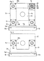
- the support plate 13 is a square frame as a result of the recess 34.
- the cover plate 13 ' is U-shaped.
- the cylinders 16a ah of the support plate 13 are tube sections.
- the cylinders 116 of the piston-cylinder units are cup-shaped castings which are centered with flat contact surfaces on corresponding contact surfaces of the support plate 113. These castings are integrated in the rigid, stationary guide rails for the movable platen 112 in that they are supported with their cylinder bottoms 116g on ring shoulders 130 of the spars 114.
- the cylinder bottoms 116g penetrated by the bearing journals 114a are braced by means of the screw nuts 117 with the support plate 113 also penetrated by the spars 114.
- the abutment shoulders 130, the lateral surfaces of the bearing pins 114a and the abutment surfaces of the screw nuts act as centering surfaces, which ensure a high stability and mechanical strength of the guide frame and thus also an exact guidance of the pistons I16b in the cylinders 116.
- the pistons 116b rest against the ring shoulder 116h of the sleeves 116f and are secured in this position by known means against axial displacement.
Landscapes
- Engineering & Computer Science (AREA)
- Manufacturing & Machinery (AREA)
- Mechanical Engineering (AREA)
- Moulds For Moulding Plastics Or The Like (AREA)
- Injection Moulding Of Plastics Or The Like (AREA)
Priority Applications (2)
| Application Number | Priority Date | Filing Date | Title |
|---|---|---|---|
| EP83109738A EP0139771B1 (fr) | 1983-09-29 | 1983-09-29 | Unité de fermeture de moule pour une machine à mouler par injection des matières plastiques |
| AT83109738T ATE34119T1 (de) | 1983-09-29 | 1983-09-29 | Formschliesseinheit einer kunststoffspritzgiessmaschine. |
Applications Claiming Priority (1)
| Application Number | Priority Date | Filing Date | Title |
|---|---|---|---|
| EP83109738A EP0139771B1 (fr) | 1983-09-29 | 1983-09-29 | Unité de fermeture de moule pour une machine à mouler par injection des matières plastiques |
Publications (3)
| Publication Number | Publication Date |
|---|---|
| EP0139771A2 true EP0139771A2 (fr) | 1985-05-08 |
| EP0139771A3 EP0139771A3 (en) | 1986-03-12 |
| EP0139771B1 EP0139771B1 (fr) | 1988-05-11 |
Family
ID=8190712
Family Applications (1)
| Application Number | Title | Priority Date | Filing Date |
|---|---|---|---|
| EP83109738A Expired EP0139771B1 (fr) | 1983-09-29 | 1983-09-29 | Unité de fermeture de moule pour une machine à mouler par injection des matières plastiques |
Country Status (2)
| Country | Link |
|---|---|
| EP (1) | EP0139771B1 (fr) |
| AT (1) | ATE34119T1 (fr) |
Cited By (2)
| Publication number | Priority date | Publication date | Assignee | Title |
|---|---|---|---|---|
| EP0480351A1 (fr) * | 1990-10-08 | 1992-04-15 | Sumitomo Heavy Industries, Ltd | Dispositif de fermeture pour presse à injection |
| CN109822075A (zh) * | 2019-03-20 | 2019-05-31 | 烟台路通精密科技股份有限公司 | 一种采用电液混动开合模机构的低压铸造机 |
Family Cites Families (3)
| Publication number | Priority date | Publication date | Assignee | Title |
|---|---|---|---|---|
| CH525767A (de) * | 1970-11-05 | 1972-07-31 | Hehl Karl | Auf Trägerholmen gelagerte Spritzeinheit, insbesondere für eine Spritzgiessmaschine |
| DE2414668C3 (de) * | 1974-03-27 | 1981-03-26 | Karl 72290 Loßburg Hehl | Hydraulischer Arbeitszylinder für die Formschließvorrichtung einer Kunststoff-Spritzgießmaschine |
| DE3226908C1 (de) * | 1982-07-17 | 1987-11-12 | Karl 7298 Loßburg Hehl | Formschließeinheit einer Kunststoffspritzgießmaschine |
-
1983
- 1983-09-29 EP EP83109738A patent/EP0139771B1/fr not_active Expired
- 1983-09-29 AT AT83109738T patent/ATE34119T1/de not_active IP Right Cessation
Cited By (4)
| Publication number | Priority date | Publication date | Assignee | Title |
|---|---|---|---|---|
| EP0480351A1 (fr) * | 1990-10-08 | 1992-04-15 | Sumitomo Heavy Industries, Ltd | Dispositif de fermeture pour presse à injection |
| US5195431A (en) * | 1990-10-08 | 1993-03-23 | Sumitomo Heavy Industries, Ltd. | Shutter-type clamping device |
| CN109822075A (zh) * | 2019-03-20 | 2019-05-31 | 烟台路通精密科技股份有限公司 | 一种采用电液混动开合模机构的低压铸造机 |
| CN109822075B (zh) * | 2019-03-20 | 2023-08-29 | 烟台路通精密科技股份有限公司 | 一种采用电液混动开合模机构的低压铸造机 |
Also Published As
| Publication number | Publication date |
|---|---|
| EP0139771A3 (en) | 1986-03-12 |
| EP0139771B1 (fr) | 1988-05-11 |
| ATE34119T1 (de) | 1988-05-15 |
Similar Documents
| Publication | Publication Date | Title |
|---|---|---|
| DE2631603A1 (de) | Formenschliesseinheit einer spritzgiessmaschine | |
| EP0449055A2 (fr) | Elévateur pour véhicules automobiles | |
| EP1313601B1 (fr) | Plateau porte-moule d'une presse d'injection | |
| DE69808429T2 (de) | Stösselträger für eine spritzgiessmaschine | |
| EP0786599B1 (fr) | Système de commande actionné par un fluide sous pression avec un cylindre et un piston plungeur | |
| EP3710222A1 (fr) | Unité de fermeture de moule destinée à une machine de moulage par injection ainsi que procédé de blocage d'un élément de transmission de force | |
| EP0316561A1 (fr) | Unité pour mouler par injection de la matière plastique | |
| DE3226908C1 (de) | Formschließeinheit einer Kunststoffspritzgießmaschine | |
| EP0220634B1 (fr) | Dispositif de fermeture pour outils de moulage, notamment pour la fabrication de pièces moulées en polyuréthane | |
| EP0139771B1 (fr) | Unité de fermeture de moule pour une machine à mouler par injection des matières plastiques | |
| DE29811648U1 (de) | Vorrichtung zum zentrierten Spannen von Werkstücken o.dgl. | |
| DE10323309B4 (de) | Vorrichtung und Verfahren zum Schließen von Werkzeugaufnahmeplatten | |
| AT18276U1 (de) | Schließeinheit sowie Formgebungsmaschine mit einer solchen Schließeinheit | |
| EP0421088A2 (fr) | Dispositif de fermeture de moule pour une machine à mouler par injection | |
| DE19744986C1 (de) | Formschließeinheit für eine Spritzgießmaschine | |
| DE2436969A1 (de) | Druckmittelkolben, insbesondere fuer druckmittelzylinder | |
| DE1779677A1 (de) | Formmaschine,insbesondere Spritzgussmaschine od.dgl. | |
| DE102016002305B4 (de) | Schließeinheit einer Formgebungsmaschine | |
| EP1480808B1 (fr) | Dispositif de fermeture monte sur une machine de moulage a injection de matiere plastique | |
| DE2112701A1 (de) | Formschliessvorrichtung,insbesondere fuer kunststoffverarbeitende Spritzgiessmaschinen | |
| AT400023B (de) | Werkzeugschliess- und verriegelungsvorrichtung für spritzgiessmaschinen | |
| DE1214393B (de) | Spritzgiessmaschine zur Verarbeitung von Kunststoffen, insbesondere thermoplastischen Kunststoffen | |
| AT526987B1 (de) | Anordnung aus einer Formaufspannplatte für eine Formgebungsmaschine und zumindest einer Verriegelungsvorrichtung | |
| DE3914846A1 (de) | Spritzgiesspresse fuer kunststoff-formmassen | |
| EP0484781B1 (fr) | Presse à refouler de brames pour laminoirs à chaud à larges bandes |
Legal Events
| Date | Code | Title | Description |
|---|---|---|---|
| PUAI | Public reference made under article 153(3) epc to a published international application that has entered the european phase |
Free format text: ORIGINAL CODE: 0009012 |
|
| AK | Designated contracting states |
Designated state(s): AT CH FR GB IT LI NL |
|
| PUAL | Search report despatched |
Free format text: ORIGINAL CODE: 0009013 |
|
| AK | Designated contracting states |
Kind code of ref document: A3 Designated state(s): AT CH FR GB IT LI NL |
|
| 17P | Request for examination filed |
Effective date: 19860520 |
|
| 17Q | First examination report despatched |
Effective date: 19871029 |
|
| GRAA | (expected) grant |
Free format text: ORIGINAL CODE: 0009210 |
|
| AK | Designated contracting states |
Kind code of ref document: B1 Designated state(s): AT CH FR GB IT LI NL |
|
| PG25 | Lapsed in a contracting state [announced via postgrant information from national office to epo] |
Ref country code: NL Effective date: 19880511 Ref country code: IT Free format text: LAPSE BECAUSE OF FAILURE TO SUBMIT A TRANSLATION OF THE DESCRIPTION OR TO PAY THE FEE WITHIN THE PRESCRIBED TIME-LIMIT;WARNING: LAPSES OF ITALIAN PATENTS WITH EFFECTIVE DATE BEFORE 2007 MAY HAVE OCCURRED AT ANY TIME BEFORE 2007. THE CORRECT EFFECTIVE DATE MAY BE DIFFERENT FROM THE ONE RECORDED. Effective date: 19880511 Ref country code: FR Free format text: THE PATENT HAS BEEN ANNULLED BY A DECISION OF A NATIONAL AUTHORITY Effective date: 19880511 |
|
| REF | Corresponds to: |
Ref document number: 34119 Country of ref document: AT Date of ref document: 19880515 Kind code of ref document: T |
|
| PG25 | Lapsed in a contracting state [announced via postgrant information from national office to epo] |
Ref country code: LI Effective date: 19880930 Ref country code: CH Effective date: 19880930 |
|
| EN | Fr: translation not filed | ||
| NLV1 | Nl: lapsed or annulled due to failure to fulfill the requirements of art. 29p and 29m of the patents act | ||
| GBV | Gb: ep patent (uk) treated as always having been void in accordance with gb section 77(7)/1977 [no translation filed] | ||
| PG25 | Lapsed in a contracting state [announced via postgrant information from national office to epo] |
Ref country code: GB Free format text: LAPSE BECAUSE OF NON-PAYMENT OF DUE FEES Effective date: 19881123 |
|
| PLBE | No opposition filed within time limit |
Free format text: ORIGINAL CODE: 0009261 |
|
| STAA | Information on the status of an ep patent application or granted ep patent |
Free format text: STATUS: NO OPPOSITION FILED WITHIN TIME LIMIT |
|
| 26N | No opposition filed | ||
| REG | Reference to a national code |
Ref country code: CH Ref legal event code: PL |
|
| PGFP | Annual fee paid to national office [announced via postgrant information from national office to epo] |
Ref country code: AT Payment date: 19920924 Year of fee payment: 10 |
|
| PG25 | Lapsed in a contracting state [announced via postgrant information from national office to epo] |
Ref country code: AT Effective date: 19930929 |