EP0139778A1 - Dispositif pour visionner des cartes d'images et pour l'enregistrement/reproduction co-ordonnés des informations sonores - Google Patents
Dispositif pour visionner des cartes d'images et pour l'enregistrement/reproduction co-ordonnés des informations sonores Download PDFInfo
- Publication number
- EP0139778A1 EP0139778A1 EP83110771A EP83110771A EP0139778A1 EP 0139778 A1 EP0139778 A1 EP 0139778A1 EP 83110771 A EP83110771 A EP 83110771A EP 83110771 A EP83110771 A EP 83110771A EP 0139778 A1 EP0139778 A1 EP 0139778A1
- Authority
- EP
- European Patent Office
- Prior art keywords
- sound
- arrangement according
- magazine
- recording
- movement
- Prior art date
- Legal status (The legal status is an assumption and is not a legal conclusion. Google has not performed a legal analysis and makes no representation as to the accuracy of the status listed.)
- Withdrawn
Links
- 230000008859 change Effects 0.000 claims description 36
- 230000015654 memory Effects 0.000 claims description 16
- 238000000034 method Methods 0.000 claims description 12
- 230000008569 process Effects 0.000 claims description 8
- 238000010168 coupling process Methods 0.000 claims description 6
- 230000008878 coupling Effects 0.000 claims description 4
- 238000005859 coupling reaction Methods 0.000 claims description 4
- 230000007246 mechanism Effects 0.000 claims description 3
- 239000003112 inhibitor Substances 0.000 claims description 2
- 238000004146 energy storage Methods 0.000 claims 1
- 230000003287 optical effect Effects 0.000 claims 1
- 230000001419 dependent effect Effects 0.000 abstract 1
- 241000446313 Lamella Species 0.000 description 2
- 230000000694 effects Effects 0.000 description 2
- 230000006870 function Effects 0.000 description 2
- 230000007704 transition Effects 0.000 description 2
- 238000004026 adhesive bonding Methods 0.000 description 1
- 230000003321 amplification Effects 0.000 description 1
- 230000015572 biosynthetic process Effects 0.000 description 1
- 239000000969 carrier Substances 0.000 description 1
- 239000000428 dust Substances 0.000 description 1
- 238000005516 engineering process Methods 0.000 description 1
- 239000003292 glue Substances 0.000 description 1
- 238000003199 nucleic acid amplification method Methods 0.000 description 1
- 238000003825 pressing Methods 0.000 description 1
Images
Classifications
-
- G—PHYSICS
- G09—EDUCATION; CRYPTOGRAPHY; DISPLAY; ADVERTISING; SEALS
- G09B—EDUCATIONAL OR DEMONSTRATION APPLIANCES; APPLIANCES FOR TEACHING, OR COMMUNICATING WITH, THE BLIND, DEAF OR MUTE; MODELS; PLANETARIA; GLOBES; MAPS; DIAGRAMS
- G09B5/00—Electrically-operated educational appliances
- G09B5/06—Electrically-operated educational appliances with both visual and audible presentation of the material to be studied
- G09B5/062—Combinations of audio and printed presentations, e.g. magnetically striped cards, talking books, magnetic tapes with printed texts thereon
Definitions
- the invention relates to an arrangement for viewing picture cards and coordinated recording and / or playing sound information.
- the object of the invention is to provide an arrangement with the features mentioned in the preamble of claim 1, in which loose photo positives or generally paper pictures can be arranged in any order, but without connecting them, after which they can be set to each other and at Viewing the images, the sound recorded for each image can be played again without paying any attention to the assignment of image and sound.
- the images are filled into the magazine.
- the slide switch is actuated, the image presented for viewing is exchanged for another image from the stack, although all images can be viewed one after the other, but the Sequence is maintained since the stack is rearranged cyclically. But if you want to change something in the order, this is still possible, since the pictures remain loose.
- the basic design of such change magazines is known.
- the sound carrier is also housed in the magazine, for example in the form of a magnetic tape cuff.
- the number of audio tracks on the carrier is equal to the maximum number of images that can be accommodated in the magazine, and each time a slide switch movement, an image is changed and a new audio track is selected, which can then be played one or more times depending on the type of arrangement.
- the synchronization or, more precisely, the assignment of associated image and sound recording is carried out exclusively by actuating the change slide.
- the magazine with interchangeable slide which belongs to the arrangement according to the invention, contains the sound carrier and is delivered either empty directly to the consumer or with freshly copied prints directly from the copier. No manipulation of the images themselves is necessary, so that previously "silent" images from archive stocks can also be set to music.
- the constructive solution is simplified if the stack is placed over the sound carrier and if the outside dimensions of the magazine with regard to length and width by the image dimensions and depth by the thickness of the stack and the space required for the sound carrier.
- the recording and reproducing device can be completely built into the magazine itself, partly built into the magazine and connected to an outer part, or all parts required for the recording and reproducing process, apart from the sound carrier itself, can be accommodated in an external device with which the magazine can be coupled by pushing it in, plugging it on or in some other way.
- the sound carrier can be attached directly in the magazine as a plate or as a strip.
- a scanning system for example a sound head, must be movable relative to the fixed disk or strip in both the scanning direction and the track changing direction, which requires a relatively large space for the movement of the scanning system. If the scanning system is arranged outside the magazine in the recording and reproducing device, the magazine then has a relatively large opening, which is closed again by a cover for the protection of the sound carrier after the magazine has been removed from the device.
- the sound carrier Through the circulation of the sound carrier, either the relative movement between the scanning system and the sound carrier for recording and playback or for changing lanes is brought about. If the recording and playback direction is not running, a sound recording can be played back endlessly. In any case, the new track must be selected together with the picture change. This is done, for example, by mechanically coupling the slide to a lane change mechanism in such a way that the track is switched by one track width when the change slide moves back and forth.
- the lane change mechanism is preferably so placed that the return to the first track is also done by operating the slide switch at a selectable position, which in turn is set, depending on the number of images in the magazine. It is possible to effect the track change by shifting the scanning system relative to a sound carrier from track to track, as well as by shifting the sound carrier itself by one track width relative to the fixed scanning system. This is also possible if the sound carrier itself is circumferential.
- the tracks can be arranged next to one another transversely to the direction of rotation and the track head is offset in tracks relative to the cuff width.
- a cuff can also be arranged in such a way that it is scanned across the direction of rotation by the sound head and is rotated step by step if a lane change should take place.
- the magazine advantageously has an opening through which access to the sound track for recording or reproduction takes place. For reasons of maintaining dust protection and also for aesthetic reasons, such an opening is closed again when the magazine is uncoupled from the device, e.g. through a hinged or sliding lid.
- a control signal in an inaudible frequency range can be recorded on the respective sound recording track, for example when the end of the sound recording associated with a projected image, which then triggers the image change movement, for example for the fully automatic and continuous presentation of a sound and to enable image viewing. This is useful, for example, for lectures or advertising events.
- a relative movement between the sound carrier and the sound head is required for the recording and reproduction, the sound head being intended to bear against the magnetic track with a certain force, and for the transition from track to track a relative movement is transverse to the recording - and playback movement required.
- the concern during the recording or playback process should, however, advantageously be interrupted when a lane change takes place. This can also be controlled or effected by the slide actuation.
- the uniform recording or playback relative movement between the sound carrier and the sound head and the return of the sound head to its starting position, which is necessary if the track does not form a closed loop, can be carried out in a conventional manner by an electric motor. It is but also possible to control the return movement of the sound head also by the slide switch actuation of the magazine or to effect it directly.
- a particularly inexpensive and very compact embodiment can be obtained when a mechanical energy dispenser, for example a spring, is charged by the alternating movement of the interchangeable slide, which then supplies the feed energy for the uniform scanning movement of the sound head and possibly also for its return to the starting position and / or changing lanes.
- Inhibitors are known from other fields of technology, by means of which the energy delivery of such a charged energy store is possible in a uniform enough manner for uniformity which is sufficient for today's quality requirements.
- the energy that can be applied during the alternating movement and that can be stored in the mechanical memory will generally be sufficient for several scanning and resetting processes. Otherwise, the energy store can be recharged by actuating the change slide, but the change movement is not carried out completely, and therefore no picture change takes place.
- the kinetic energy required for changing lanes can also be obtained from a mechanical energy store charged by the change-over slide actuation.
- a mechanical energy store does not only do the rigging inexpensive, but also correspondingly increases the lifespan of batteries required for electronic amplification, which no longer need to supply the energy for the movement of the head and / or the movement of the lane change.
- the magazine has a sound memory or sound carrier common to all inserted cards, and a sound head for scanning the sound carrier is built into the magazine.
- FIG. 4 shows the magazine 139 in a section transverse to the narrow side of the essentially rectangular magazine.
- a self-contained sound carrier sleeve 140 is rotatably placed over deflection rollers 141 and 142; the Roller 142 is driven by a (not shown) in a T onwieder- display portion of a motor.
- a pressure plate 144 Under a sound head 143 is a pressure plate 144, which are under tension from two leaf springs 145 towards the sound head, so that the sound head can come into operative connection with the sleeve 140.
- the sound head 143 is held in a plastic housing 146 (see also FIG. 6).
- Two ribs 147 serve to guide it in the scanning direction.
- Two contact springs 148 conduct the electrical signals on two busbars 149 and from there to two external contacts 150 which, like the drive, are connected to the recording and reproducing device (not shown).
- the structure of the plastic housing 146 for the sound head 143 can be seen in FIG. 6.
- the housing has the two contact springs 148 and a driver cam 151 which is movable in the vertical direction (in the drawing).
- This cam has two functions: in operative connection with a transport rake 152, it is used to move the sound head to a new track when changing the image and, on the other hand, to return the sound head with its housing to the starting position when the relevant image sequence, which is stored in the magazine, is used once went through.
- FIG 3 shows the mode of operation of the transport rake 152.
- the slide 153 runs onto the nose 154 of the transport rake 152 and pushes it back into a starting position in the magazine housing 155 regardless of the position which it had previously taken.
- the plastic housing 146 for the sound head 143 is taken along the same path by arranged on the transport rake lamella 156, which can evade individually in the manner of leaf springs.
- the rake 152 can dodge, the biasing springs 157 giving way.
- the lamella which lies immediately in front of the cam 151, also springs back because it is displaced by the cam. This slat then takes over the active function, etc.
- Fig. 1 shows the control of the cam 151 for the sound head guide.
- the wedge 158 pushes the cam 151 upwards when it reaches its end position, so that it can be gripped by the tooth 159 of the interchangeable slide 153 and pulled upward with it.
- the wedge 160 presses the cam 151 down again.
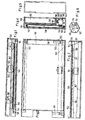
- Fig. 2 shows the components installed in the cassette base 161, in particular the sleeve 140
- Fig. 5 shows the front view of the slide 153, the wall of which, when closed, covers the card storage compartment 162 and the audio sleeve part of the magazine.
- the wedge 158 can be designed to be adjustable from the outside, so that the sound head on the cuff, after scanning the sound track assigned to the last card of the card stack, immediately returns to the starting position Scanning the track for the first card being transported.
- the cam 151 is pushed upward at a position lying further inwards and is then gripped by tooth 159 of the interchangeable slide.
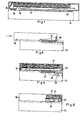
- FIG. 7 to 10 show the arrangement in a second embodiment.
- the bottom of a magazine 86 is coupled to a recording and reproducing device 85 by sliding.
- the coupled state is shown in Fig. 7 in a side view, partially in longitudinal section.
- Fig. 8 shows schematically the process of the clutch.
- a displaceable cover 87 is provided on the underside of the magazine 86 and meets a stop cam 88 when the magazine is pushed onto a sliding guide of the device 85.
- the two parts finally assume the position according to FIG. 9, the cover 87, because it is in contact with the cam 88, displacing relative to the magazine and thus clearing an opening on the underside of the magazine.
- the head 89 of the recording and reproducing apparatus can now be activated by means (not shown), i.e. it is lifted through the opening into the magazine until it resiliently rests on the underside of the bottom card 90 of the stack 91 at the point where the cards have a sound track. Thereafter, the sound head can be moved perpendicular to the plane of the drawing in a manner known per se by uniform movement relative to this sound track, so that the recording or the reproduction can take place approximately according to the magnetic-sound method.
- the sound head 89 here scans the sound track on the bottom card of the stack, while the top card of the stack is presented to the viewer through the window of the magazine, the assignment of image information and sound information is ensured as long as the order of the cards in the magazine remains unchanged and no card is removed or added. Since the sequence of the cards in the magazine is not changed by the change slide actuation, but the cards are only shifted cyclically, the assignment remains unaffected by the change process.
Landscapes
- Engineering & Computer Science (AREA)
- Multimedia (AREA)
- Business, Economics & Management (AREA)
- Physics & Mathematics (AREA)
- Educational Administration (AREA)
- Educational Technology (AREA)
- General Physics & Mathematics (AREA)
- Theoretical Computer Science (AREA)
- Electrically Operated Instructional Devices (AREA)
- Recording Or Reproducing By Magnetic Means (AREA)
Priority Applications (2)
| Application Number | Priority Date | Filing Date | Title |
|---|---|---|---|
| EP83110771A EP0139778A1 (fr) | 1983-10-27 | 1983-10-27 | Dispositif pour visionner des cartes d'images et pour l'enregistrement/reproduction co-ordonnés des informations sonores |
| JP22662184A JPS60125878A (ja) | 1983-10-27 | 1984-10-26 | 画像表示および音響録音再生装置 |
Applications Claiming Priority (1)
| Application Number | Priority Date | Filing Date | Title |
|---|---|---|---|
| EP83110771A EP0139778A1 (fr) | 1983-10-27 | 1983-10-27 | Dispositif pour visionner des cartes d'images et pour l'enregistrement/reproduction co-ordonnés des informations sonores |
Publications (1)
| Publication Number | Publication Date |
|---|---|
| EP0139778A1 true EP0139778A1 (fr) | 1985-05-08 |
Family
ID=8190781
Family Applications (1)
| Application Number | Title | Priority Date | Filing Date |
|---|---|---|---|
| EP83110771A Withdrawn EP0139778A1 (fr) | 1983-10-27 | 1983-10-27 | Dispositif pour visionner des cartes d'images et pour l'enregistrement/reproduction co-ordonnés des informations sonores |
Country Status (2)
| Country | Link |
|---|---|
| EP (1) | EP0139778A1 (fr) |
| JP (1) | JPS60125878A (fr) |
Cited By (4)
| Publication number | Priority date | Publication date | Assignee | Title |
|---|---|---|---|---|
| EP0681206A1 (fr) * | 1994-05-03 | 1995-11-08 | Eastman Kodak Company | Album de photos parlant |
| GB2390218B (en) * | 2001-03-15 | 2005-05-11 | Ron Hu | Picture changer with recording and playback capability |
| US6990293B2 (en) | 2001-03-15 | 2006-01-24 | Ron Hu | Picture changer with recording and playback capability |
| CN113168779A (zh) * | 2019-11-05 | 2021-07-23 | 山东英才学院 | 一种辅助儿童识物的分体式早教机 |
Citations (9)
| Publication number | Priority date | Publication date | Assignee | Title |
|---|---|---|---|---|
| US3296925A (en) * | 1962-10-26 | 1967-01-10 | Matsushita Electric Industrial Co Ltd | Picture projecting and sound record reproducing magazines |
| US3563644A (en) * | 1969-05-12 | 1971-02-16 | Kalart Co Inc | Sound slide projector system |
| DE2219865A1 (de) * | 1971-04-23 | 1972-11-09 | Staar Development Co. S.A., Brüssel | Diapositivträger mit Zusatzeinrichtung zur Tonaufzeichnung und Einrichtungen für die audiovisuelle Wiedergabe |
| US3704337A (en) * | 1969-04-07 | 1972-11-28 | Information Transfer Corp | Tactile response teaching system |
| DE2352001A1 (de) * | 1973-10-17 | 1975-05-07 | Prontor Werk Gauthier Gmbh | Ton- und bildwiedergabegeraet auf audiovisueller grundlage |
| US3883238A (en) * | 1973-12-26 | 1975-05-13 | Panayotis C Dimitracopoulos | Audiovisual slides and apparatus |
| US3997917A (en) * | 1974-04-01 | 1976-12-14 | Sony Corporation | Card handling apparatus |
| US4072989A (en) * | 1976-01-07 | 1978-02-07 | Minnesota Mining And Manufacturing Company | Audio-visual presentation device |
| US4245417A (en) * | 1977-09-20 | 1981-01-20 | Licinvest Ag | Picture viewer |
-
1983
- 1983-10-27 EP EP83110771A patent/EP0139778A1/fr not_active Withdrawn
-
1984
- 1984-10-26 JP JP22662184A patent/JPS60125878A/ja active Pending
Patent Citations (9)
| Publication number | Priority date | Publication date | Assignee | Title |
|---|---|---|---|---|
| US3296925A (en) * | 1962-10-26 | 1967-01-10 | Matsushita Electric Industrial Co Ltd | Picture projecting and sound record reproducing magazines |
| US3704337A (en) * | 1969-04-07 | 1972-11-28 | Information Transfer Corp | Tactile response teaching system |
| US3563644A (en) * | 1969-05-12 | 1971-02-16 | Kalart Co Inc | Sound slide projector system |
| DE2219865A1 (de) * | 1971-04-23 | 1972-11-09 | Staar Development Co. S.A., Brüssel | Diapositivträger mit Zusatzeinrichtung zur Tonaufzeichnung und Einrichtungen für die audiovisuelle Wiedergabe |
| DE2352001A1 (de) * | 1973-10-17 | 1975-05-07 | Prontor Werk Gauthier Gmbh | Ton- und bildwiedergabegeraet auf audiovisueller grundlage |
| US3883238A (en) * | 1973-12-26 | 1975-05-13 | Panayotis C Dimitracopoulos | Audiovisual slides and apparatus |
| US3997917A (en) * | 1974-04-01 | 1976-12-14 | Sony Corporation | Card handling apparatus |
| US4072989A (en) * | 1976-01-07 | 1978-02-07 | Minnesota Mining And Manufacturing Company | Audio-visual presentation device |
| US4245417A (en) * | 1977-09-20 | 1981-01-20 | Licinvest Ag | Picture viewer |
Cited By (6)
| Publication number | Priority date | Publication date | Assignee | Title |
|---|---|---|---|---|
| EP0681206A1 (fr) * | 1994-05-03 | 1995-11-08 | Eastman Kodak Company | Album de photos parlant |
| US5574519A (en) * | 1994-05-03 | 1996-11-12 | Eastman Kodak Company | Talking photoalbum |
| GB2390218B (en) * | 2001-03-15 | 2005-05-11 | Ron Hu | Picture changer with recording and playback capability |
| US6990293B2 (en) | 2001-03-15 | 2006-01-24 | Ron Hu | Picture changer with recording and playback capability |
| CN113168779A (zh) * | 2019-11-05 | 2021-07-23 | 山东英才学院 | 一种辅助儿童识物的分体式早教机 |
| CN113168779B (zh) * | 2019-11-05 | 2022-06-28 | 温州大学 | 一种辅助儿童识物的分体式早教机 |
Also Published As
| Publication number | Publication date |
|---|---|
| JPS60125878A (ja) | 1985-07-05 |
Similar Documents
| Publication | Publication Date | Title |
|---|---|---|
| DE3006735C2 (de) | Videosignal-Aufzeichnungs- und/oder Wiedergabegerät | |
| DE1190691B (de) | Magnetbandgeraet mit mehreren auswechselbaren Kassetten | |
| DE3239659C2 (fr) | ||
| DE1522984A1 (de) | Bandaufzeichnungs- und Wiedergabegeraet und dafuer bestimmte Bandkassette | |
| DE1229750B (de) | Ton- und Bild-Wiedergabegeraet und Ton-Bild-Traeger zur Verwendung mit einem solchen Geraet | |
| DE1762641B2 (de) | Anordnung zur aufzeichnung und/oder wiedergabe von video-signalen | |
| DE2324657A1 (de) | Tonbandkassette fuer hohe bandlaufgeschwindigkeit | |
| DE2752730C2 (fr) | ||
| DE3218759A1 (de) | Audio-visuelle cassette und audiospieler, kombiniert mit einem bildbetrachter | |
| EP0139778A1 (fr) | Dispositif pour visionner des cartes d'images et pour l'enregistrement/reproduction co-ordonnés des informations sonores | |
| EP0139779A1 (fr) | Dispositif pour regarder des images et pour enregistrer/reproduire des sons | |
| DE1128165B (de) | Kassetten-Magnettongeraete mit bandfoermigem Aufzeichnungstraeger | |
| DE2021135C3 (de) | Gerät zur magnetischen Aufzeichnung und Wiedergabe von Information | |
| DE3021751C2 (de) | Einrichtung zum Be- und Entladen von Cassetten von Videorecordern | |
| DE2134794A1 (de) | Tonfilm-Apparatur | |
| DE4032957A1 (de) | Videorekorder mit mehreren einbaulaufwerken | |
| DE2053756A1 (de) | Tonbandgerat | |
| EP0351727B1 (fr) | Magasin pour cassette | |
| DE1762990C (de) | Videobandgerät mit einem Gehäuse, mit dem lösbar eine Bandkassette verbindbar ist. Ausscheidung aus: 1537240 | |
| DE2462650C2 (de) | Kassettenadapter für Mikrokassetten | |
| DE2653957A1 (de) | Audiovisuelles geraet | |
| DE1943052A1 (de) | Projektor fuer feststehende Bilder mit Tonwiedergabe | |
| DE1041529B (de) | Anordnung zur magnetischen Informationsspeicherung | |
| DE3603921C2 (fr) | ||
| DE2219865C3 (de) | Vorrichtung zur koordinierten BiId- und Tonwiedergabe |
Legal Events
| Date | Code | Title | Description |
|---|---|---|---|
| PUAI | Public reference made under article 153(3) epc to a published international application that has entered the european phase |
Free format text: ORIGINAL CODE: 0009012 |
|
| AK | Designated contracting states |
Designated state(s): AT BE CH DE FR GB IT LI LU NL SE |
|
| 17P | Request for examination filed |
Effective date: 19851003 |
|
| 17Q | First examination report despatched |
Effective date: 19861008 |
|
| STAA | Information on the status of an ep patent application or granted ep patent |
Free format text: STATUS: THE APPLICATION HAS BEEN WITHDRAWN |
|
| 18W | Application withdrawn |
Withdrawal date: 19870204 |
|
| RIN1 | Information on inventor provided before grant (corrected) |
Inventor name: ACKERET, PETER |