EP0139909A2 - Elément de construction sanitaire pour régler la distribution ainsi que l'évacuation de l'eau dans ou hors d'une baignoire ou similaire - Google Patents
Elément de construction sanitaire pour régler la distribution ainsi que l'évacuation de l'eau dans ou hors d'une baignoire ou similaire Download PDFInfo
- Publication number
- EP0139909A2 EP0139909A2 EP84109160A EP84109160A EP0139909A2 EP 0139909 A2 EP0139909 A2 EP 0139909A2 EP 84109160 A EP84109160 A EP 84109160A EP 84109160 A EP84109160 A EP 84109160A EP 0139909 A2 EP0139909 A2 EP 0139909A2
- Authority
- EP
- European Patent Office
- Prior art keywords
- water
- shut
- hydrosanitary
- mixing
- unit
- Prior art date
- Legal status (The legal status is an assumption and is not a legal conclusion. Google has not performed a legal analysis and makes no representation as to the accuracy of the status listed.)
- Granted
Links
Images


Classifications
-
- E—FIXED CONSTRUCTIONS
- E03—WATER SUPPLY; SEWERAGE
- E03C—DOMESTIC PLUMBING INSTALLATIONS FOR FRESH WATER OR WASTE WATER; SINKS
- E03C1/00—Domestic plumbing installations for fresh water or waste water; Sinks
- E03C1/02—Plumbing installations for fresh water
- E03C1/04—Water-basin installations specially adapted to wash-basins or baths
-
- E—FIXED CONSTRUCTIONS
- E03—WATER SUPPLY; SEWERAGE
- E03C—DOMESTIC PLUMBING INSTALLATIONS FOR FRESH WATER OR WASTE WATER; SINKS
- E03C1/00—Domestic plumbing installations for fresh water or waste water; Sinks
- E03C1/12—Plumbing installations for waste water; Basins or fountains connected thereto; Sinks
- E03C1/22—Outlet devices mounted in basins, baths, or sinks
- E03C1/23—Outlet devices mounted in basins, baths, or sinks with mechanical closure mechanisms
- E03C1/232—Outlet devices mounted in basins, baths, or sinks with mechanical closure mechanisms combined with overflow devices
Definitions
- the above invention relates to a hydrosanitary unit for controlling and regulating the flow of water to or from a consumer, e.g. a bathtub.
- bathtubs have a device at their head end, which makes it possible to act on the stopper of the water drain in order to close the water drainage or to open it for emptying the bathtub.
- This device usually also has a drain opening which serves as an overflow for the bathtub.
- the object of the above invention is to avoid the disadvantages of the prior art and to propose a hydrosanitary unit which, in a simple and cost-effective manner, can accommodate all the control and operating devices required in a single, compact body which is arranged between the bathroom wall and the bathtub wall are to operate the bathtub drain, regulate the mixture and the amount of water to the bathtub or hand shower, and also provide an inlet opening and an opening that serves at the same time as a bath tub abundance.
- a further object of the above invention is to design the construction body of the hydrosanitary construction unit in such a simple manner that the possibility is created of simply building the construction body e.g. by means of die casting in metal or a suitable plastic, and to allow the use of automatic machines both for machining and for the subsequent polishing processes.
- a basic body which has connecting pieces for the supply of cold water and warm water, and that a connecting piece is also provided for connecting a hand shower, that this body has an opening which serves as a drain opening, and is connected to a drain pipe and furthermore an actuating device for opening and closing the tub drain plug is provided that channels for warm water and cold water open into a mixing chamber, to which a rotating disk for mixing. and shut off the
- this rotatable disc has holes or recesses that are assigned to water inlet openings, that the rotatable disc has a tubular extension on its back, which protrudes sealed into a bore that is connected to the nozzle for the shower connection that on the front of the mixing disc combines with a tubular body, in the wall of which a number of circumferential openings for the It is provided that the cold water enters, that the wall of the tubular body ends in a chamber into which the tubular component is connected, which is connected to the mixing disk, that the tubular extension has through-holes in the circumferential direction, and has a blocking means which can be displaced in the axial direction, and that the wall end of the tubular body has a further number of through holes in the circumferential direction, which enables the water to exit in the direction of the bathtub.
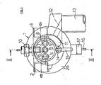
- the hydrosanitary unit consists of a body 1, which is produced, for example, as a cast component and connecting pieces. 2 and 3 for the supply of has warm, as well as cold water.
- the sockets 2 and 3 are connected to outflow channels 4 and 5 which are provided in a wall 6 of the body 1, the wall forming the bottom of a chamber 7 which is delimited by a cylindrical wall 8.
- a further bore 9 is provided which is connected to a connection piece 10 which is provided for the water inflow to a hand shower (not shown).
- the body 1 On its front side, the body 1 has an opening 11 which serves as an overflow opening for the tub and is connected via a channel 12 to a drain pipe 13 which is fastened to the body 1. Under the wall 8, the body 1 receives a longitudinal pin 14 which is rotatably mounted and via a lever 15 or. a similar actuation means can be driven.
- the pin 14 is operatively connected to an actuating device for a cable pull 16 or for an actuating rod, which are provided for opening and closing a stopper (not shown) which is assigned to the outflow of the bathtub.
- the actuating rope 16 is received by a piece of pipe 17 which is fixedly arranged on the body 1.
- FIG. 2 which shows the body 1 of the structural unit in rear view
- the rotatably mounted pin 14 is fixedly connected to a disk 18 which is mounted in a chamber 19 which is delimited by a cylindrical wall 20 is, which in turn is firmly connected to the body 1.
- the disc 18 has also a bearing pin 21, which is provided eccentrically with respect to the axis of rotation of the pin 14, and this pin 21 receives a small sleeve 22 which is fixedly connected to the actuating rope 16, which is guided in the pipe section 17 and in a manner known per se is used to drive the stopper actuation device, thus creating the possibility of opening or closing the bathtub drain.
- the wall 20 has an internal thread 23, which receives the threaded part of an end cover 24 (FIG. 3).
- the body 1 has on its front side a flange 25, with which, advantageously with the interposition of a seal 26, it bears against the inner wall of the bathtub 27, to which, with the aid of a threaded nut 28, which is screwed onto the external thread of the cylindrical wall 8, the flange 25 is pressed.
- This cylindrical wall 8 as can be seen in FIG. 3, protrudes towards the front and forms a cylindrical chamber, which is identified by 7.
- the chamber 7 receives a mixer and shut-off disc 29 which is rotatable about the Laerigsachse X.
- the disk 29 has two bores or openings 30 and 31 which are assigned to the bores 4 and 5 (FIGS. 1 and 2) which are provided for the supply of hot and cold water (flanges 2 and 3).
- the disk 29 does not require a more precise description, since its function as a mixer and shut-off disk is already known ceramic discs that Ar t, belonging to the state of the art and find numerous mixing valves, cold and hot water use is known.
- a tubular body 32 protrudes, which has an O-ring seal, which is identified by 33 and inserted into the bore 9 which is in communication with the flange 10 leading to the shower.
- the tubular component 32 continues and penetrates a pipe socket 34, the end of which is screwed into the end piece of the wall 8.
- the tubular component 32 finally ends in a pin 35 which has a polygonal cross section.
- a chamber 36 is formed inside the tube flange 34, and the tubular member has circumferential through holes, and are on both sides of the through holes. Sealing means arranged, advantageously O-rings, which are marked with 38 and 39. Furthermore, the wall of the tube flange 34 is penetrated by a number of bores 40, which are also arranged in the circumferential direction.
- the end 35 with a polygonal cross section of the tubular body 32 is arranged in a seat 41, which has the same shape as the pin 42 and makes it possible to transmit the disk 29 a rotational movement and at the same time to enable the pin 42 in the axial direction to be moved.
- the axially displaceable pin 42 has at its end directed towards the disk 29 a thickening 43 which serves as a shut-off means (valve cone) and cooperates with a valve seat 44 which is provided in accordance with the bores 40 of the inner wall of the pipe socket 34.
- the pipe socket 34 has a number of continuous bores 45 in the circumferential direction, which will be described in more detail below, and it is further provided that the thickening 43 of the pin 42 is acted upon by a spring means 46 which tends to pin the pin 42 to move in the direction of the mixer disc 29.
- the end of the pin 42 which is opposite the thickening 43, has a handle 47 in order to facilitate the rotational movement and the axial displacement of the pin; it is thus possible to set the mixer disk 29 in a rotary movement and to impart an axial movement to the thickening serving as a shut-off part.
- the actuating device 15 of the shaft 14 is only shown as a threaded pin in FIGS. 1 to 3, of course this threaded pin can be provided by a Annular rotatable component or the like can be added, which forms an integral part of the housing 48.
Landscapes
- Engineering & Computer Science (AREA)
- Public Health (AREA)
- Health & Medical Sciences (AREA)
- Life Sciences & Earth Sciences (AREA)
- Hydrology & Water Resources (AREA)
- Water Supply & Treatment (AREA)
- Environmental & Geological Engineering (AREA)
- Mechanical Engineering (AREA)
- Domestic Plumbing Installations (AREA)
- Control For Baths (AREA)
- Multiple-Way Valves (AREA)
- Bathtubs, Showers, And Their Attachments (AREA)
- Devices For Medical Bathing And Washing (AREA)
- Percussion Or Vibration Massage (AREA)
- Nozzles (AREA)
Priority Applications (1)
| Application Number | Priority Date | Filing Date | Title |
|---|---|---|---|
| AT84109160T ATE43383T1 (de) | 1983-08-09 | 1984-08-02 | Hydrosanitaere baueinheit zum regeln und steuern des wasserzuflusses sowie des wasserflusses in oder von einer badewanne oder aehnlichem. |
Applications Claiming Priority (2)
| Application Number | Priority Date | Filing Date | Title |
|---|---|---|---|
| IT22484/83A IT1164406B (it) | 1983-08-09 | 1983-08-09 | Unita' idrosanitaria per regolare e comandare l'alimentazione nonche' lo scarico dell'acqua verso e da una vasca da bagno o utilizzatore simile |
| IT2248483 | 1983-08-09 |
Publications (3)
| Publication Number | Publication Date |
|---|---|
| EP0139909A2 true EP0139909A2 (fr) | 1985-05-08 |
| EP0139909A3 EP0139909A3 (en) | 1985-12-11 |
| EP0139909B1 EP0139909B1 (fr) | 1989-05-24 |
Family
ID=11196891
Family Applications (1)
| Application Number | Title | Priority Date | Filing Date |
|---|---|---|---|
| EP84109160A Expired EP0139909B1 (fr) | 1983-08-09 | 1984-08-02 | Elément de construction sanitaire pour régler la distribution ainsi que l'évacuation de l'eau dans ou hors d'une baignoire ou similaire |
Country Status (4)
| Country | Link |
|---|---|
| EP (1) | EP0139909B1 (fr) |
| AT (1) | ATE43383T1 (fr) |
| DE (1) | DE3478321D1 (fr) |
| IT (1) | IT1164406B (fr) |
Cited By (3)
| Publication number | Priority date | Publication date | Assignee | Title |
|---|---|---|---|---|
| FR2667891A1 (fr) * | 1990-10-12 | 1992-04-17 | Piat Moise | Robinetterie pour bain-douche incorporee au boitier de surverse. |
| GB2228068B (en) * | 1989-01-04 | 1993-06-30 | Arthur Stanley Hunnibal | Remote control hot water tap |
| EP0674054A1 (fr) * | 1994-03-10 | 1995-09-27 | Elio Garlaschelli | Dispositif de contrôle d'eau pour baignoire |
Family Cites Families (7)
| Publication number | Priority date | Publication date | Assignee | Title |
|---|---|---|---|---|
| DE1759946B1 (de) * | 1968-06-24 | 1971-11-18 | Zimmer & Kellermann | Mischbatterie zum Wandanbau |
| DE7027210U (de) * | 1970-07-20 | 1970-11-05 | Grohe Kg Hans | Ueberlaufvorrichtung fuer badewannen und dergleichen. |
| IT950157B (it) * | 1972-03-14 | 1973-06-20 | Giacomini A | Gruppo idraulico di comando per vasca da bagno |
| ES423932A1 (es) * | 1973-03-24 | 1976-05-16 | Grohe Armaturen Friedrich | Un grifo mezclador. |
| DE2651559A1 (de) * | 1976-11-11 | 1978-05-18 | Seidl Armaturen | Automatische brause-wanne-umstellung fuer badearmatur |
| US4331176A (en) * | 1980-03-03 | 1982-05-25 | American Standard Inc. | Replaceable cartridge valve assembly |
| FR2506886A1 (fr) * | 1981-05-27 | 1982-12-03 | Chantoiseau Sa Robinetterie | Robinet mitigeur d'eau |
-
1983
- 1983-08-09 IT IT22484/83A patent/IT1164406B/it active
-
1984
- 1984-08-02 DE DE8484109160T patent/DE3478321D1/de not_active Expired
- 1984-08-02 AT AT84109160T patent/ATE43383T1/de active
- 1984-08-02 EP EP84109160A patent/EP0139909B1/fr not_active Expired
Cited By (4)
| Publication number | Priority date | Publication date | Assignee | Title |
|---|---|---|---|---|
| GB2228068B (en) * | 1989-01-04 | 1993-06-30 | Arthur Stanley Hunnibal | Remote control hot water tap |
| FR2667891A1 (fr) * | 1990-10-12 | 1992-04-17 | Piat Moise | Robinetterie pour bain-douche incorporee au boitier de surverse. |
| WO1992007209A1 (fr) * | 1990-10-12 | 1992-04-30 | Piat Moise | Mitigeur sanitaire a deux robinets |
| EP0674054A1 (fr) * | 1994-03-10 | 1995-09-27 | Elio Garlaschelli | Dispositif de contrôle d'eau pour baignoire |
Also Published As
| Publication number | Publication date |
|---|---|
| EP0139909B1 (fr) | 1989-05-24 |
| IT1164406B (it) | 1987-04-08 |
| DE3478321D1 (en) | 1989-06-29 |
| EP0139909A3 (en) | 1985-12-11 |
| ATE43383T1 (de) | 1989-06-15 |
| IT8322484A0 (it) | 1983-08-09 |
Similar Documents
| Publication | Publication Date | Title |
|---|---|---|
| DE60006928T2 (de) | Vorrichtung zum Abgeben und Mischen von Wasser | |
| DE19623104A1 (de) | Als Einhebelmischer ausgebildete Sanitärarmatur | |
| DE102004018277B4 (de) | Mischventil für eine einarmige, nur durch Drehen betätigbare Mischbatterie | |
| CH661969A5 (de) | Sequenzgesteuerter wassermischer. | |
| EP1853769A1 (fr) | Systeme de douche | |
| DE2219325A1 (de) | Bedienungsaggregat fuer badewannen | |
| DE7717102U1 (de) | Eingriffwassermischhahnventil | |
| DE69721248T2 (de) | Durchflussregelungsvorrichtung mit einem mittels unerschöpflicher energie gesteuertem ventil | |
| CH659276A5 (de) | Sanitaere wasserausgabeeinrichtung mit heisswasserbereiter und mit einer zapfvorrichtung. | |
| EP0139909B1 (fr) | Elément de construction sanitaire pour régler la distribution ainsi que l'évacuation de l'eau dans ou hors d'une baignoire ou similaire | |
| DE19510670C2 (de) | Wasserführende Sanitärarmatur | |
| DE2653754A1 (de) | Wannfuell- und brausebatterie | |
| DE2045060A1 (de) | Mischbatterie | |
| DE2543112C3 (de) | Mischarmatur für sanitäre Anlagen o.dgl. | |
| DE2020075A1 (de) | Mischventil,insbesondere fuer Wasser und Wasserdampf | |
| DE10258832A1 (de) | Ventil | |
| DE3306690A1 (de) | Wasserauslaufventil | |
| EP0855635B1 (fr) | Robinetterie sanitaire | |
| DE102006042626A1 (de) | Sanitärarmatur | |
| DE1963451B2 (de) | Mischbatterie fuer sanitaere anlagen | |
| DE7827331U1 (de) | Einloch-mischbatterie mit einhandbedienung | |
| DE3506078A1 (de) | Handbrause fuer duschanlagen | |
| CH479013A (de) | Zapfstelle für Fluida | |
| DE2907565A1 (de) | Kombinierte selbstschluss- und mischarmatur | |
| AT89101B (de) | Selbstschließendes Mischventil, insbesondere für Badezwecke. |
Legal Events
| Date | Code | Title | Description |
|---|---|---|---|
| PUAI | Public reference made under article 153(3) epc to a published international application that has entered the european phase |
Free format text: ORIGINAL CODE: 0009012 |
|
| AK | Designated contracting states |
Designated state(s): AT BE CH DE FR GB LI LU NL SE |
|
| PUAL | Search report despatched |
Free format text: ORIGINAL CODE: 0009013 |
|
| AK | Designated contracting states |
Designated state(s): AT BE CH DE FR GB LI LU NL SE |
|
| 17P | Request for examination filed |
Effective date: 19860430 |
|
| 17Q | First examination report despatched |
Effective date: 19880502 |
|
| GRAA | (expected) grant |
Free format text: ORIGINAL CODE: 0009210 |
|
| AK | Designated contracting states |
Kind code of ref document: B1 Designated state(s): AT BE CH DE FR GB LI LU NL SE |
|
| PG25 | Lapsed in a contracting state [announced via postgrant information from national office to epo] |
Ref country code: SE Effective date: 19890524 Ref country code: NL Effective date: 19890524 Ref country code: BE Effective date: 19890524 |
|
| REF | Corresponds to: |
Ref document number: 43383 Country of ref document: AT Date of ref document: 19890615 Kind code of ref document: T |
|
| GBT | Gb: translation of ep patent filed (gb section 77(6)(a)/1977) | ||
| REF | Corresponds to: |
Ref document number: 3478321 Country of ref document: DE Date of ref document: 19890629 |
|
| PGFP | Annual fee paid to national office [announced via postgrant information from national office to epo] |
Ref country code: GB Payment date: 19890731 Year of fee payment: 6 |
|
| PG25 | Lapsed in a contracting state [announced via postgrant information from national office to epo] |
Ref country code: AT Effective date: 19890802 |
|
| PGFP | Annual fee paid to national office [announced via postgrant information from national office to epo] |
Ref country code: FR Payment date: 19890807 Year of fee payment: 6 |
|
| PGFP | Annual fee paid to national office [announced via postgrant information from national office to epo] |
Ref country code: DE Payment date: 19890811 Year of fee payment: 6 |
|
| PG25 | Lapsed in a contracting state [announced via postgrant information from national office to epo] |
Ref country code: LU Free format text: LAPSE BECAUSE OF NON-PAYMENT OF DUE FEES Effective date: 19890831 Ref country code: LI Effective date: 19890831 Ref country code: CH Effective date: 19890831 |
|
| ET | Fr: translation filed | ||
| NLV1 | Nl: lapsed or annulled due to failure to fulfill the requirements of art. 29p and 29m of the patents act | ||
| PLBE | No opposition filed within time limit |
Free format text: ORIGINAL CODE: 0009261 |
|
| STAA | Information on the status of an ep patent application or granted ep patent |
Free format text: STATUS: NO OPPOSITION FILED WITHIN TIME LIMIT |
|
| REG | Reference to a national code |
Ref country code: CH Ref legal event code: PL |
|
| 26N | No opposition filed | ||
| PG25 | Lapsed in a contracting state [announced via postgrant information from national office to epo] |
Ref country code: GB Effective date: 19900802 |
|
| GBPC | Gb: european patent ceased through non-payment of renewal fee | ||
| PG25 | Lapsed in a contracting state [announced via postgrant information from national office to epo] |
Ref country code: FR Effective date: 19910430 |
|
| PG25 | Lapsed in a contracting state [announced via postgrant information from national office to epo] |
Ref country code: DE Effective date: 19910501 |
|
| REG | Reference to a national code |
Ref country code: FR Ref legal event code: ST |