EP0139927A2 - Connecting rod - Google Patents
Connecting rod Download PDFInfo
- Publication number
- EP0139927A2 EP0139927A2 EP84109409A EP84109409A EP0139927A2 EP 0139927 A2 EP0139927 A2 EP 0139927A2 EP 84109409 A EP84109409 A EP 84109409A EP 84109409 A EP84109409 A EP 84109409A EP 0139927 A2 EP0139927 A2 EP 0139927A2
- Authority
- EP
- European Patent Office
- Prior art keywords
- connecting rod
- shaft
- rod according
- wave
- cast iron
- Prior art date
- Legal status (The legal status is an assumption and is not a legal conclusion. Google has not performed a legal analysis and makes no representation as to the accuracy of the status listed.)
- Withdrawn
Links
- 238000005266 casting Methods 0.000 claims abstract description 6
- 229910001296 Malleable iron Inorganic materials 0.000 claims abstract description 3
- 229910001141 Ductile iron Inorganic materials 0.000 claims abstract 2
- 239000000463 material Substances 0.000 abstract description 5
- 238000009825 accumulation Methods 0.000 abstract description 3
- 230000015572 biosynthetic process Effects 0.000 abstract description 2
- 238000007493 shaping process Methods 0.000 abstract description 2
- 230000035508 accumulation Effects 0.000 description 2
- 238000004519 manufacturing process Methods 0.000 description 2
- 230000007704 transition Effects 0.000 description 2
- OKTJSMMVPCPJKN-UHFFFAOYSA-N Carbon Chemical compound [C] OKTJSMMVPCPJKN-UHFFFAOYSA-N 0.000 description 1
- 229910001018 Cast iron Inorganic materials 0.000 description 1
- 238000001816 cooling Methods 0.000 description 1
- 230000001419 dependent effect Effects 0.000 description 1
- 238000005516 engineering process Methods 0.000 description 1
- 229910002804 graphite Inorganic materials 0.000 description 1
- 239000010439 graphite Substances 0.000 description 1
- 230000006872 improvement Effects 0.000 description 1
Images
Classifications
-
- F—MECHANICAL ENGINEERING; LIGHTING; HEATING; WEAPONS; BLASTING
- F16—ENGINEERING ELEMENTS AND UNITS; GENERAL MEASURES FOR PRODUCING AND MAINTAINING EFFECTIVE FUNCTIONING OF MACHINES OR INSTALLATIONS; THERMAL INSULATION IN GENERAL
- F16C—SHAFTS; FLEXIBLE SHAFTS; ELEMENTS OR CRANKSHAFT MECHANISMS; ROTARY BODIES OTHER THAN GEARING ELEMENTS; BEARINGS
- F16C7/00—Connecting-rods or like links pivoted at both ends; Construction of connecting-rod heads
- F16C7/02—Constructions of connecting-rods with constant length
- F16C7/023—Constructions of connecting-rods with constant length for piston engines, pumps or the like
Definitions
- the present invention relates to a connecting rod with a large and a small bearing eye and a shaft connecting the bearing eyes.
- the connecting rod is used to connect a reciprocating piston to the crank pin of a rotating crankshaft.
- the connecting rod must withstand all loads during operation, i.e. it must not break. It also has to keep stiff.
- the technical development is aimed on the one hand at saving weight, on the other hand at higher speeds and consequently at more heavily loaded connecting rods.
- the shape, material selection and manufacturing quality must meet the increased operational requirements.
- connecting rod shaft elongated, square or rectangular cross-sections with rounded corners, as well as oval and elliptical cross-sections.
- Such cross-sections of the shank can often be the source of errors due to the material accumulation, which leads to the connecting rod being rejected.
- the object of the present invention is to propose a connecting rod in which, on the one hand, weight savings are achieved by free shaping in the shaft area with the same component strength, and on the other hand a quality improvement is achieved by reducing the cavity volume.
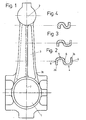
- Fig. 1 shows a connecting rod which consists essentially of a large bearing eye 1, a small bearing eye 2 and a shaft 3 connecting the two bearing eyes.
- the connecting shaft has an essentially undulating cross section.
- the wave form of the shaft consists of a wave trough 4 and a wave crest 5. These wave elements are provided along the entire shaft 3 and range from the small bearing eye 2 to the large bearing eye 1. Both the wave crest 5 and the wave trough 4 take from the small bearing eye 2 in the direction of the large bearing eye 1 in width.
- the area 6 of the shaft 3 which transitions from the wave trough 4 to the wave crest 5 runs between the two bearing eyes in the axis of symmetry 7 of the connecting rod.
- the wave shape in the cross section of the shaft is essentially a right-angled broken wave line, and a sinusoidal shape is also conceivable.
- the shaft 3 has laterally extending legs 8 and 9 which connect the bearing eyes to one another.
- the free edges 3a, 3b of the legs project diametrically away from each other.
- the wave valleys and wave crests run out in an arc.
- the connecting rod described is preferably produced in a casting process.
- the proposed shape of the connecting rod shaft is particularly advantageous from a casting point of view, because material accumulations can be avoided and an essentially constant wall thickness is achieved.
- the wave-shaped design also brings special advantages in terms of strength.
- Cast iron with nodular graphite and pearlitic malleable cast iron are particularly suitable as materials for the production of the connecting rod described.
Landscapes
- Engineering & Computer Science (AREA)
- General Engineering & Computer Science (AREA)
- Mechanical Engineering (AREA)
- Shafts, Cranks, Connecting Bars, And Related Bearings (AREA)
Abstract
Es wird ein Pleuel vorgeschlagen, dessen Schaft (3) einen im wesentlichen wellenförmigen Querschnitt aufweist. Der wellenförmige Verlauf des Querschnittes des Pleuelschaftes kann sowohl in einer rechtwinklig gebrochenen Linie als auch sinusförmig erfolgen. Der vorgeschlagene Pleuel ist in einem Giessverfahren hergestellt und besteht vorzugsweise aus Gusseisen mit Kugelgraphit oder aus Temperguss.A connecting rod is proposed, the shaft (3) of which has an essentially undulating cross section. The wavy course of the cross-section of the connecting rod shaft can be either in a broken line at right angles or sinusoidally. The proposed connecting rod is produced in a casting process and is preferably made of spheroidal graphite cast iron or malleable cast iron.
Durch die vorgeschlagene Formgebung wird eine Kombination von giesstechnischen und festigkeitsmässigen Vorteilen erzielt. Einerseits wird durch Vermeidung von Materialanhäufung die Lunkerbildung verhindert, andererseits werden die Bauteilfestigkeitswerte durch die Wellenform erheblich gesteigert.
Description
Die vorliegende Erfindung betrifft einen Pleuel mit einem grossen und einem kleinen Lagerauge und einem die Lageraugen verbindenden Schaft.The present invention relates to a connecting rod with a large and a small bearing eye and a shaft connecting the bearing eyes.
Der Pleuel dient zur Verbindung eines hin- und hergehenden Kolbens mit dem Kurbelzapfen einer sich drehenden Kurbelwelle. Der Pleuel muss allen Beanspruchungen im Betrieb standhalten, d.h., er darf nicht brechen. Darüber hinaus muss er steif halten.The connecting rod is used to connect a reciprocating piston to the crank pin of a rotating crankshaft. The connecting rod must withstand all loads during operation, i.e. it must not break. It also has to keep stiff.
Die technische Entwicklung zielt einerseits auf Gewichtseinsparung, andererseits auf höhere Drehzahlen und infolge dessen auf stärker belastete Pleuelstangen. Um die geforderte Betriebssicherheit eines Pleuels zu gewährleisten, muss die Formgestaltung, Materialauswahl und die Herstellungsqualität den gestellten erhöhten betrieblichen Anforderungen genügen.The technical development is aimed on the one hand at saving weight, on the other hand at higher speeds and consequently at more heavily loaded connecting rods. In order to guarantee the required operational safety of a connecting rod, the shape, material selection and manufacturing quality must meet the increased operational requirements.
Herkömmliche Gusspleuel werden mit einem doppel T-förmigen Pleuelschaft von 3 bis 5 mm gegossen, so dass in den Knotenpunkten im Mittelsteg wegen der geringen Kühlung Lunkerbildungen nur durch aufwendige giesstechnische . Massnahmen zu verhindern sind.Conventional cast connecting rods are cast with a double T-shaped connecting rod shaft of 3 to 5 mm, so that in the Because of the low cooling, the formation of cavities in the central web only through complex casting technology. Measures must be prevented.
Verschiedene Querschnittsformen sind für den Pleuelschaft bekannt: Längliche, quatratische oder rechteckige Querschnitte mit abgerundeten Ecken, sowie ovale und eliptische Querschnitte. Solche Schaftquerschnitte können infolge der Materialanhäufung oft die Fehlerquelle sein, die zum Ausschuss des Pleuels führt.Different cross-sectional shapes are known for the connecting rod shaft: elongated, square or rectangular cross-sections with rounded corners, as well as oval and elliptical cross-sections. Such cross-sections of the shank can often be the source of errors due to the material accumulation, which leads to the connecting rod being rejected.
Aufgabe der vorliegenden Erfindung ist es, einen Pleuel vorzuschlagen, bei dem durch freie Formgebung im Schaftbereich bei gleichbleibender Bauteilfestigkeit einerseits Gewichtseinsparungen erzielt werden, andererseits durch Verminderung des Lunkervolumens eine Qualitätsverbesserung erzielt wird.The object of the present invention is to propose a connecting rod in which, on the one hand, weight savings are achieved by free shaping in the shaft area with the same component strength, and on the other hand a quality improvement is achieved by reducing the cavity volume.
Diese Aufgabe wird durch die Lehre des Anspruches 1 gelöst.This object is achieved by the teaching of claim 1.
Weitere vorteilhafte Ausgestaltungen gehen aus den abhängigen Ansprüchen hervor.Further advantageous refinements emerge from the dependent claims.
Anhand der beigelegten Figuren wird ein bevorzugtes Ausführungsbeispiel näher erläutert.A preferred exemplary embodiment is explained in more detail with reference to the attached figures.
Es zeigen:
- Fig. 1 eine Draufsicht auf einen erfindungsgemässen Pleuel,
- Fig. 2 - Querschnitte des Pleuelschaftes aus der 4 Fig. 1.
- 1 is a plan view of a connecting rod according to the invention,
- FIG. 2 - cross sections of the connecting rod shaft from FIG. 4.
Die Fig. 1 zeigt einen Pleuel, der im wesentlichen aus einem grossen Lagerauge 1, einem kleinen Lagerauge 2 und einem die beiden Lageraugen verbindenden Schaft 3 besteht. Der Verbindungsschaft weist einen im wesentlichen wellenförmigen Querschnitt auf. Die Wellenform des Schaftes besteht aus einem Wellental 4 und aus einem Wellenberg 5. Diese Wellenelemente sind entlang des gesamten Schaftes 3 vorgesehen und reichen vom kleinen Lagerauge 2 zum grossen Lagerauge 1. Sowohl der Wellenberg 5 wie das Wellental 4 nehmen vom kleinen Lagerauge 2 in Richtung des grossen Lagerauges 1 an Breite zu. Der vom Wellental 4 zum Wellenberg 5 übergehende Bereich 6 des Schaftes 3 verläuft zwischen den beiden Lageraugen in der Symmetrieachse 7 des Pleuels. Der Wellenverlauf im Querschnitt des Schaftes ist im wesentlichen eine rechtwinklig gebrochene Wellenlinie, wobei auch ein sinusförmiger Verlauf denkbar ist.Fig. 1 shows a connecting rod which consists essentially of a large bearing eye 1, a small bearing
Der Schaft 3 weist seitlich verlaufende Schenkel 8 und 9 auf, die die Lageraugen miteinander verbinden. Die freien Ränder 3a, 3b der Schenkel ragen diametral voneinander weg. Im Bereich des Ueberganges vom Schaft 3 zu den Lageraugen laufen die Wellentäler und die Wellenberge bogenförmig aus.The
Der beschriebene Pleuel wird vorzugsweise in einem Giessverfahren hergestellt. Die vorgeschlagene Formgebung des Pleuelschaftes ist insbesondere aus giesstechnischer Sicht vorteilhaft, weil sich Materialanhäufungen vermeiden lassen und eine im wesentlichen gleichbleibende Wandstärke erzielt wird. Die wellenförmige Ausgestaltung bringt zudem festigkeitsmässig besondere Vorteile.The connecting rod described is preferably produced in a casting process. The proposed shape of the connecting rod shaft is particularly advantageous from a casting point of view, because material accumulations can be avoided and an essentially constant wall thickness is achieved. The wave-shaped design also brings special advantages in terms of strength.
Als Material für die Herstellung des beschriebenen Pleuels eignen sich besonders Gusseisen mit Kugelgraphit und perlitischer Temperguss.Cast iron with nodular graphite and pearlitic malleable cast iron are particularly suitable as materials for the production of the connecting rod described.
Claims (10)
Applications Claiming Priority (2)
| Application Number | Priority Date | Filing Date | Title |
|---|---|---|---|
| CH486983 | 1983-09-06 | ||
| CH4869/83 | 1983-09-06 |
Publications (2)
| Publication Number | Publication Date |
|---|---|
| EP0139927A2 true EP0139927A2 (en) | 1985-05-08 |
| EP0139927A3 EP0139927A3 (en) | 1985-08-14 |
Family
ID=4283970
Family Applications (1)
| Application Number | Title | Priority Date | Filing Date |
|---|---|---|---|
| EP84109409A Withdrawn EP0139927A3 (en) | 1983-09-06 | 1984-08-08 | Connecting rod |
Country Status (2)
| Country | Link |
|---|---|
| EP (1) | EP0139927A3 (en) |
| ES (1) | ES290701Y (en) |
Family Cites Families (1)
| Publication number | Priority date | Publication date | Assignee | Title |
|---|---|---|---|---|
| US1540523A (en) * | 1923-02-26 | 1925-06-02 | Stephen D Hartog | Connecting rod |
-
1984
- 1984-08-08 EP EP84109409A patent/EP0139927A3/en not_active Withdrawn
- 1984-09-05 ES ES1984290701U patent/ES290701Y/en not_active Expired
Also Published As
| Publication number | Publication date |
|---|---|
| ES290701U (en) | 1986-03-16 |
| EP0139927A3 (en) | 1985-08-14 |
| ES290701Y (en) | 1986-10-16 |
Similar Documents
| Publication | Publication Date | Title |
|---|---|---|
| DE4342415C2 (en) | Tension-optimized thread profile | |
| DE2854052C2 (en) | Pulley for toothed belt drives | |
| DE4019997A1 (en) | BALL JOINT | |
| EP0421056A2 (en) | Plastic fastening element | |
| DE69207416T2 (en) | FRICTION ANCHOR FOR ROCK | |
| DE4034384C2 (en) | ||
| DE3511851C2 (en) | Slotted oil control ring inserted into a ring groove at the lower end of a plunger | |
| DE2204852A1 (en) | Flexible element for glasses frames | |
| EP0206190B1 (en) | Connecting element for two machine components or structural members | |
| DE2723653A1 (en) | DEVICE FOR ESTABLISHING AN UNREACHABLE CONNECTION AND AN UNREACHABLE CONNECTION ESTABLISHED WITH THIS DEVICE | |
| DE1946403A1 (en) | Piston pin | |
| DE3039382A1 (en) | LIGHT TACH PISTON FOR COMBUSTION ENGINES | |
| DE69517779T2 (en) | Elastic coupling for rotating shafts | |
| DE3614227A1 (en) | CRANKSHAFT MADE OF AN IRON METAL MATERIAL FOR LIFTING PISTON MACHINES | |
| DE602004003699T2 (en) | FLANGE CONNECTION WHERE AT LEAST ONE FLANGE IS SPREADED IN A ROTATABLE WAY | |
| DE3843330A1 (en) | Cast insert | |
| DE3238489A1 (en) | Connecting rod | |
| DE2351994C2 (en) | Power unit for reciprocating engines | |
| DE3225450A1 (en) | Stirring tool | |
| DE1284762B (en) | Light metal pistons, especially for internal combustion engines | |
| DE3447339A1 (en) | CASTING ROD | |
| DE2258090A1 (en) | COMPRESSIBLE METAL BELLOW | |
| DE4433252C2 (en) | Connecting rod with cross-section optimized for buckling stiffness | |
| DE3218047A1 (en) | CONTAINER FOR HERMETICALLY SEALED ENGINE COMPRESSOR ASSEMBLIES FOR COOLING SYSTEMS | |
| DE3234765A1 (en) | GRIPPER PROJECTILE FOR WEAVING MACHINES |
Legal Events
| Date | Code | Title | Description |
|---|---|---|---|
| PUAI | Public reference made under article 153(3) epc to a published international application that has entered the european phase |
Free format text: ORIGINAL CODE: 0009012 |
|
| 17P | Request for examination filed |
Effective date: 19840808 |
|
| AK | Designated contracting states |
Designated state(s): AT DE FR GB IT |
|
| PUAL | Search report despatched |
Free format text: ORIGINAL CODE: 0009013 |
|
| AK | Designated contracting states |
Designated state(s): AT DE FR GB IT |
|
| RHK1 | Main classification (correction) |
Ipc: F16C 7/02 |
|
| 17Q | First examination report despatched |
Effective date: 19860428 |
|
| STAA | Information on the status of an ep patent application or granted ep patent |
Free format text: STATUS: THE APPLICATION HAS BEEN WITHDRAWN |
|
| 18W | Application withdrawn |
Withdrawal date: 19861022 |
|
| RIN1 | Information on inventor provided before grant (corrected) |
Inventor name: MAHNIG, FRITZ Inventor name: SCHULTE, GUENTER Inventor name: SCHMITT, HANS |