EP0139962A2 - Auslösevorrichtung für einen Spülkasten - Google Patents
Auslösevorrichtung für einen Spülkasten Download PDFInfo
- Publication number
- EP0139962A2 EP0139962A2 EP84109790A EP84109790A EP0139962A2 EP 0139962 A2 EP0139962 A2 EP 0139962A2 EP 84109790 A EP84109790 A EP 84109790A EP 84109790 A EP84109790 A EP 84109790A EP 0139962 A2 EP0139962 A2 EP 0139962A2
- Authority
- EP
- European Patent Office
- Prior art keywords
- bell
- overflow pipe
- flushing
- cistern
- flushing medium
- Prior art date
- Legal status (The legal status is an assumption and is not a legal conclusion. Google has not performed a legal analysis and makes no representation as to the accuracy of the status listed.)
- Granted
Links
- 238000011010 flushing procedure Methods 0.000 claims abstract description 31
- XLYOFNOQVPJJNP-UHFFFAOYSA-N water Substances O XLYOFNOQVPJJNP-UHFFFAOYSA-N 0.000 claims abstract description 28
- 125000006850 spacer group Chemical group 0.000 claims abstract description 9
- 230000000630 rising effect Effects 0.000 claims description 3
- 230000001174 ascending effect Effects 0.000 claims 1
- 230000007704 transition Effects 0.000 claims 1
- 230000000694 effects Effects 0.000 abstract description 4
- 230000004913 activation Effects 0.000 abstract 2
- 230000003213 activating effect Effects 0.000 abstract 1
- 238000000034 method Methods 0.000 description 6
- 238000005406 washing Methods 0.000 description 4
- 230000001105 regulatory effect Effects 0.000 description 2
- 238000004904 shortening Methods 0.000 description 2
- 230000015572 biosynthetic process Effects 0.000 description 1
- 238000010276 construction Methods 0.000 description 1
- 230000001934 delay Effects 0.000 description 1
- 230000002028 premature Effects 0.000 description 1
- 238000007789 sealing Methods 0.000 description 1
- 238000009423 ventilation Methods 0.000 description 1
Images


Classifications
-
- E—FIXED CONSTRUCTIONS
- E03—WATER SUPPLY; SEWERAGE
- E03D—WATER-CLOSETS OR URINALS WITH FLUSHING DEVICES; FLUSHING VALVES THEREFOR
- E03D1/00—Water flushing devices with cisterns ; Setting up a range of flushing devices or water-closets; Combinations of several flushing devices
- E03D1/02—High-level flushing systems
- E03D1/14—Cisterns discharging variable quantities of water also cisterns with bell siphons in combination with flushing valves
- E03D2001/147—Cisterns discharging variable quantities of water also cisterns with bell siphons in combination with flushing valves having provisions for active interruption of flushing
Definitions
- the invention relates to a trigger device for a cistern z.
- a water closet with a lift flushing device consisting of an overflow pipe with a bottom valve arranged at its lower end and one overlapping the upper end of the overflow pipe leaving an opening for the flushing medium, connected to the overflow pipe via webs and only over part of the length of the top tube extending lifter bell, and with an actuating device for the triggering device, which causes the full discharge of the flushing medium when actuated and only a partial discharge of the flushing medium when actuated another.
- Such a device is known from DE-AS 11 56 714.
- the actuating device there consists of two optionally actuable actuators, one of which is connected to a braking device, which delays the return of this actuating element, which is only positively coupled to the lifting device during actuation, to the rest position.
- This arrangement is to cause the entire cistern contents to flow out once and only part of it when the other actuating device is actuated.
- the known trigger device requires two actuators and is therefore difficult to handle, ie a selection of the two actuators must be made.
- the object of the invention is to simplify the triggering device and also to design it in such a way that a certain minimum flushing medium quantity, which should be approximately half the cistern contents, expires even in the event of a rapid interruption.
- the lifter bell is connected via spacers to a float ring which is arranged in a float cup which surrounds the overflow pipe and is stationary with respect to the movement of the upper runner pipe and lifter bell and which has outlet holes in its base.
- the lifter bell preferably has a lateral, open-ended connecting piece that starts from the bell arch and is variable in length.
- This arrangement it is possible to change the subset of the flushing medium by shortening or lengthening this side nozzle accordingly.
- This arrangement also greatly reduces the gurgling noise which is present in lifting devices of this type and which is caused by the air inlet at the end of the upper lifting.
- the lifter bell with lateral holes, the arrangement of which can be variable in height, as a result of which the upper elevation is also terminated by air intake and the gurgling noise is substantially reduced. Due to the freely selectable height of the holes The minimum amount of rinse water for small rinsing is set above the lower rim of the siphon.
- the overflow pipe can have a constriction to accelerate the outflow of the flushing medium.
- the upper end pipe can be provided at its lower end with a conically tapering constriction projecting above the bottom valve. It is also possible to provide a funnel-shaped widening at the upper end of the overflow pipe. An expansion in the upper area of the bell can serve to avoid a cross-sectional constriction that occurs when the upper end of the overflow pipe is expanded in a funnel shape.
- Another possibility of changing the amount of the flushing medium flowing out is to design the spacers between the upper runner tube and the lifting bell to be height-adjustable in their distance from the float.
- the actuating device preferably consists of a rocker arm which is pivotally mounted on the cistern and is connected to the lifting bell via a lever arm.
- the drain device can also be actuated by means of a simple pull button or a hydraulically or magnetically influenced device or by means of another device.
- Float rings which are arranged in a float cup, per se belong to the prior art, as can be seen, for example, from DE-OS 25 20 760. There, however, the problem of partially or completely emptying the cistern is solved in that two float arrangements are provided.
- This amount of residual water can be influenced by a variable opening cross section of the outlet openings, so that it is possible, depending on the magnitude of the amount of water remaining in the box after the washing process, to reduce or increase the amount of washing water.
- the principle of the invention also works when the siphon bell is omitted and instead the top tube is extended and bent downwards in a U-shape, the end of this bent part being where the lower end of the siphon bell would otherwise be.
- this U-shaped bent overflow pipe have a constriction in the rising part.
- the rising part can also have a curvature against the axis of the valve, so that the bent part of the overflow pipe is symmetrical with respect to this axis.
- a length which can be changed in length if necessary, can be used, the end of which, turned away from the open end, opens out of the latter in the vicinity of the apex of the U-shaped bent overflow pipe.
- 1 denotes the cistern, which is closed by a cistern cover 2.
- the trigger button 3 is arranged in the cistern cover 2. It is in two Positions can be actuated, namely "actuation” on the one hand and “stop” on the other, as indicated in FIG. 1.
- An axis arranged in the fulcrum 3a enables a rocker-like actuation of the trigger button 3. This rocker-like actuation is excluded by simply displacing this axis. This means that the trigger button can only be used to trigger the rinsing process, but no longer to interrupt it.
- This trigger button 3 is connected to a lever arm 5, the end of which is hooked into a bracket 6, which rises on the bell bottom 4 of a lifting bell 7.
- the lifter bell 7 is connected to the overflow tube 9 by means of spacers 8, wherein the spacers can optionally also be height-adjustable, as indicated at 8a on the left-hand side of FIG. 2. However, you can also go completely from bottom to top inside the lifter bell 7.
- the spacers 8 and 8a sit on a float ring 10, which is housed in a float cup 11 and can slide on the cylindrical inner wall 12 thereof.
- the outer wall of the float cup merges into the base part 13, in which outlet openings 14 are provided.
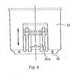
- an opening 14a with an adjustable cross section can also be present in the base part 13 or on the circumference of the float cup 11, as shown in FIG. 6.
- the valve plate 15 of which can rest on the valve seat 16 in the cistern 1.
- a button 3 ' can also be engaged on the bracket 6, which button is pulled up to initiate the washing process, as a result of which the total amount of washing water is raised drains away. If the button 3 'is pressed down again immediately after lifting, then the lifting system comes into effect and only the intended part of the rinse water flows off.
- the lifter bell 7 has a lateral, open at the bottom nozzle 17, the free end of 18 shortened in any way z. B. can be cut off in order to be able to set the desired partial discharge amount of the flushing medium.
- this shortening option can also consist in that a partial connector is inserted into the connector 17 and is fixed there, for example by means of a thread, so that it is possible to screw this partial connector more or less far into the interior of the connector 17.
- holes 17a can be arranged laterally on the circumference of the lifting bell 7, which enable premature ventilation of the lifting bell. These holes 17a can either be effective in connection with the connector 17 or alternatively, with the latter option the connector 17 can be omitted. It is also possible to only draw these holes 17a and only drill them if necessary to reduce the volume of the small flush.
- a bend 26 is provided, which makes the formation of the overflow pipe 9 in the U-shaped part substantially symmetrical to the axis X-X of the outlet valve, consisting of the valve plate 15 and the valve seat 16.
- a nozzle 28 opens out at the apex 27 of the U-shaped tube part, the end 29 of which can be shortened or lengthened if necessary.
- the connecting piece 28 corresponds to the connecting piece 17 with the end 18 according to FIG. 3.
- the contents of the cistern 1 can be brought to a complete stop by pressing the trigger button 3 in the “actuation” direction. If after pressing the trigger button 3 on the part of the trigger button 3 labeled "Stop", the rinsing process is interrupted, but only to the extent specified by the setting of the lifting bell 7. In any case, it is ensured that a certain minimum flushing medium quantity, which should be approximately half of the flushing box contents, is guaranteed even in the event of a rapid interruption by pressing the trigger button 3 in the "stop” direction.
- the overflow pipe 9 with the lifting bell 7 is raised by pressing the trigger button 3, as a result of which the valve plate 15 also lifts off the valve seat 16.
- This allows the cistern contents to flow through the nozzle at the lower end of the cistern 1 into the line leading to the toilet.
- the trigger button 3 is pressed on the "stop" side, then the head tube with the lifting bell 7 lowers and the valve plate 15 sits on the valve seat 16, so that the water flow in this direction is interrupted.
- a suction is created in the upper pipe 9, which sucks the water from the cistern through the siphon bell 7 into the overflow pipe 9, so that this water can also flow through the lower end of the upper pipe 9 into the toilet bowl.
- the water drain from the float cup 11 can be accelerated by opening the regulating device 14 a further.
- the bottom valve 15 lowers even before the total cistern content has expired, and a residual water quantity that can be adjusted with the regulating device 14 a remains in the cistern, by which the total flush water quantity of the cistern is reduced.
Landscapes
- Health & Medical Sciences (AREA)
- Life Sciences & Earth Sciences (AREA)
- Engineering & Computer Science (AREA)
- Hydrology & Water Resources (AREA)
- Public Health (AREA)
- Water Supply & Treatment (AREA)
- Sanitary Device For Flush Toilet (AREA)
- Earth Drilling (AREA)
- Nozzles (AREA)
- Fluid-Pressure Circuits (AREA)
- Sampling And Sample Adjustment (AREA)
- Bidet-Like Cleaning Device And Other Flush Toilet Accessories (AREA)
Abstract
Description
- Die Erfindung betrifft eine Auslösevorrichtung für einen Spülkasten z. B. eines Wasserklosetts mit einer Heberspüleinrichtung, bestehend aus einem überlaufrohr mit einem an seinem unteren Ende angeordneten Bodenventil und einer das obere Ende des überlaufrohrs unter Belassung einer Durchtrittsöffnung für das Spülmedium übergreifenden, mit dem überlaufrohr über Stege verbundenen und sich nur über einen Teil der Länge des Oberlaufrohrs erstreckenden Heberglocke, sowie mit einer Betätigungsvorrichtung für die Auslösevorrichtung, die bei einer Betätigung den vollen Ablauf des Spülmediums und bei einer anderen Betätigung nur einen Teilablauf des Spülmediums bewirkt.
- Eine solche Vorrichtung ist aus der DE-AS 11 56 714 bekannt. Die Betätigungsvorrichtung besteht dort aus zwei wahlweise zu betätigenden Betätigungsgliedern, von denen das eine mit einer Bremsvorrichtung verbunden ist, welche die Rückkehr dieses nur während der Betätigung mit der_Anhebevorrichtung kraftschlüssig gekoppelten Betätigungsgliedes in die Ruhestellüng verzögert.
- Zweck dieser Anordnung ist es, einmal den gesamten Spülkasteninhalt zum Ausfließen zu bringen und bei Betätigung der anderen Betätigungsvorrichtung nur einen Teil davon.
- Man kan somit die beim Spülvorgang verbrauchte Spülmediummenge begrenzen, wenn nicht die gesamte Spülmediummenge erforderlich ist. Dies ist von bedeutenderem Vorteil bei Wasserklosetts, wo auf diese Weise erheblich Wasser eingespart werden kann.
- Die bekannte Auslösevorrichtung benötigt zwei Betätigungsorgane und ist damit umständlich zu handhaben, d. h. es muß eine Auswahl der beiden Betätigungseinrichtungen getroffen werden.
- Aufgabe der Erfindung ist, die Auslösevorrichtung einfacher und außerdem derart auszubilden, daß eine bestimmte Mindestspülmediummenge, die etwa die Hälfte des Spülkasteninhalts betragen sollte, auch bei einer schnellen Unterbrechung ausläuft.
- Diese Aufgabe wird erfindungsgemäß dadurch gelöst, daß die Heberglocke über Abstandshalter mit einem Schwimmerring verbunden ist, der in einem das überlaufrohr umgebenden, gegenüber der Bewegung von Oberlaufrohr und Heberglocke ortsfesten Schwimmerbecher angeordnet ist, welcher in seinem Boden Austrittslöcher aufweist.
- Mit einer solchen Anordnung wird erreicht, daß sich einerseits das Schwimmerventil zum Wiederauffüllen des Spülkastens öffnet und andererseits der Verbrauchsstelle, beispielsweise einem WC, eine Mindestspülmediummenge zum möglichst vollständigen Austausch des Sperrwassers des Geruchsverschlusses zugeführt wird.
- Vorzugsweise weist die Heberglocke einen von der Glockenwölbung ausgehenden, in seiner Länge veränderbaren, seitlichen, offen ausmündenden Stutzen auf.
- Mit dieser Anordnung ist es möglich, die Teilmenge des Spülmediums durch entsprechendes Verkürzen oder Verlängern dieses seitlichen Stutzens zu verändern. Durch diese Anordnung wird auch das bei Hebereinrichtungen dieser Art vorhandene, durch den Lufteintritt bei Beendigung der Oberheberung bedingte, gluckernde Geräusch stark gemindert.
- Es ist jedoch auch möglich, die Heberglocke mit seitlichen Löchern deren Anordnung in der Höhe variabel sein kann, zu versehen, wodurch ebenfalls durch Lufteintritt die Oberheberung beendet und das gluckernde Geräusch wesentlich gemindert wird. Durch die frei zu wählende Höhe der Löcher über dem unteren Heberglockenrand wird die Mindestspülwassermenge für die Kleinspülung festgelegt.
- Das überlaufrohr kann zur Beschleunigung des Abströmens des Spülmediums eine Einschnürung aufweisen. Außerdem kann zur Begünstigung des Strömungsverlaufes das Oberlaufrohr an seinem unteren Ende mit einer über das Bodenventil vorstehenden konisch zulaufenden Verengung versehen sein, Es ist ferner möglich, am oberen Ende des Überlaufrohres eine trichterförmige Aufweitung vorzusehen. Eine Erweiterung im oberen Bereich der Glocke kann dazu dienen, eine Querschnittsverengung zu vermeiden, die bei einer trichterförmigen Aufweitung des oberen Endes des Überlaufrohres eintritt.
- Eine andere Möglichkeit, die Menge des ablaufenden Spülmediums zu verändern, besteht darin, die Abstandshalter zwischen Oberlaufrohr und Heberglocke in ihrem Abstand zum Schwimmer höhenverstellbar auszubilden.
- Die Betätigungsvorrichtung besteht vorzugsweise aus einem Kipphebel, der am Spülkasten schwenkbar gelagert ist und über einen Hebelarm mit der Heberglocke in Verbindung steht.
- Die Betätigung der Ablaufvorrichtung kann auch mittels eines einfachen Zugknopfes oder einer hydraulisch oder magnetisch beeinflußten Vorrichtung oder mit Hilfe einer anderen Vorrichtung erfolgen.
- Schwimmerringe, die in einem Schwimmerbecher angeordnet sind, gehören an sich zum Stande der Technik, wie sich beispielsweise aus der DE-OS 25 20 760 ergibt. Dort wird jedoch das Problem, den Spülkasten teilweise oder ganz zu leeren dadurch gelöst, daß zwei Schwimmeranordnungen vorgesehen sind.
- Auch Kipphebel zur Betätigung des Wasserablaufventils bei Spülkästen gehören zum Stande der Technik, wie sich beispielsweise aus dem DE-Gbm 82 23 943 ergibt. Dort wird jedoch das Problem, den Spülkasten ganz oder teilweise nach Wahl zu entleeren dadurch gelöst, daß der Abfluß des Spülmediums durch die zweite Betätigung unmittelbar durch Schließen jeglicher Abflußmöglichkeit unterbrochen wird.
- In einigen Einsatzbereichen, z. B. Kliniken, öffentlichen WC-Anlagen usw. müssen hygienische Belange absoluten Vorrang vor der Möglichkeit des Wassersparens haben. Es wird daher vorgeschlagen, die Achse des Kipphebels so zu gestalten, daß sie leicht in dafür vorgesehene Lochaussparungen außerhalb des Betätigungsfeldes der Taste verlegt werden kann, so daß eine Unterbrechung des Spülvorganges nicht mehr möglich ist und nur mit der vollen Wassermenge gespült werden kann.
- Auch die. Anordnung von Austrittsöffnungen in einem Schwimmerbecher ist nach der DE-PS 639 760 Stand der Technik. Dabei geht es darum, dafür zu sorgen, daß sich das Oberlaufrohr mit dem Bodenventil erst schließen kann, wenn die Gesamtspülwassermenge des Spülkastens, unter Umständen bis auf eine bestimmte erwünschte Restwassermenge, ausgelaufen ist.
- Diese Restwassermenge kann durch einen variablen öffnungsquerschnitt der Austrittsöffnungen beeinflußt werden, so daß es möglich ist, je nach Größenordnung der nach dem Spülvorgang im Kasten verbleibenden Wassermenge, die Spülwassermenge herab- oder heraufzusetzen.
- Das Erfindungsprinzip funktioniert auch, wenn die Heberglocke in Wegfall kommt und statt dessen das Oberlaufrohr verlängert und nach unten U-förmig umgebogen ist, wobei das Ende dieses umgebogenen Teiles dort sitzt, wo sonst das untere Ende der Heberglocke wäre. Dabei kann in weiterer Ausbildung der Erfindun dieses U-förmig umgebogene überlaufrohr im aufsteigenden Teil eine Einschnürung aufweisen. Der aufsteigende Teil kann auch gegen die Achse des Ventils eine Abkrümmung aufweisen, so daß der gebogene Teil des überlaufrohres gegenüber dieser Achse eine Symmetrie erhält.
- Auch bei dieser Ausbildung des Hebersystems läßt sich ein in seiner Länge gegebenenfalls veränderbarer Stutzen verwenden, dessen vom offenen Ende abgewendetes Ende in der Nähe des Scheitels des U-förmig gebogenen Überlaufrohres aus diesem ausmündet.
- Die Zeichnung zeigt in
- Fig. 1 eine teilweise im Schnitt gezeichnete Vorderansicht ; eines Spülkastens; :
- Fig. 2 einen Schnitt längs der Linie II-II der Fig. 1, wobei mit I-I die Schnittebene der Fig. 1 angegeben ist;
- Fig. 3 eine Einzeldarstellung der Anordnung aus Überlaufrohr und Heberglocke gemäß einer bevorzugten Ausführungsform;
- Fig. 4 eine abgeänderte Ausführungsform des Hebersystems; und in
- Fig. 5 eine weitere abgeänderte Ausführungsform des Hebersystems;
- Fig. 6 eine Ausführungsform des Schwimmerbechers mit variablem Wasseraustrittsquerschnitt.
- In der Zeichnung ist mit 1 der Spülkasten bezeichnet, der durch einen Spülkastendeckel 2 verschlossen ist. Im Spülkastendeckel 2 ist die Auslösetaste 3 angeordnet. Sie ist in zwei Stellungen betätigbar, nämlich einmal "Betätigung" und zum anderen "Stop", wie es in Fig. 1 angegeben ist.
- Eine im Drehpunkt 3a angeordnete Achse ermöglicht eine wippenartige Betätigung der Auslösetaste 3. Durch einfaches Versetzen dieser Achse.in weiter vorgesehene Bohrungen 3b wird diese wippenartige Betätigung ausgeschlossen. Damit kann die Auslösetaste nur noch zum Auslösen des Spülvorganges, aber nicht mehr zur Unterbrechung desselben verwendet werden.
- Diese Auslösetaste 3 ist mit einem Hebelarm 5 verbunden, dessen Ende in einen Bügel 6 eingehakt ist, der sich auf dem Glockenboden 4 einer Heberglocke 7 erhebt. Die Heberglocke 7 ist über Abstandshalter 8 mit dem 0.berlaufröhr 9 verbunden, wobei die Abstandshalter gegebenenfalls, wie auf der linken Seite der Fig. 2 bei 8a angedeutet, auch höhenverstellbar sein können. Sie können allerdings auch vollständig von unten nach oben innerhaTb der Heberglocke 7 durchgehen.
- Die Abstandshalter 8 bzw. 8a sitzen auf einem Schwimmerring 10, der in einem Schwimmerbecher 11 untergebracht ist und auf dessen zylindrischer Innenwand 12 gleiten kann. Die Außenwand des Schwimmerbechers geht in den Bodenteil 13 über, in dem Austrittsöffnungen 14 vorgesehen sind. Zusätzlich oder alternativ zu diesen einfachen Austrittsöffnungen 14 kann auch im Bodenteil 13 oder am Umfang des Schwimmerbechers 11 eine in ihrem Querschnitt regulierbare öffnung 14a vorhanden sein, wie Fig: 6 zeigt. Am unteren Ende des Oberlaufrohres 9 befindet sich das Bodenventil, dessen Ventilteller 15 auf dem Ventilsitz 16 im Spülkasten 1 aufsitzen kann.
- Anstelle eines Hebelarmes kann man am Bügel 6 auch einen Knopf 3' angreifen lassen, der zum Auslösen des Spülvorganges hochgezogen wird, wodurch die gesamte Spülwassermenge abfließt. Wird der Knopf 3' nach dem Hochziehen sofort wieder heruntergedrückt, dann kommt das Hebersystem zur Wirkung und es fließt nur die vorgesehene Teilmenge des Spülwasser ab.
- In Fig. 3 ist eine abgeänderte Ausführungsform wiedergegeben. Die Heberglocke 7 weist dort einen seitlichen, unten offenen Stutzen 17 auf, dessen freies Ende bei 18 in beliebiger Weise verkürzt z. B. abgeschnitten werden kann, um derart die gewünschte Teilablaufmenge des Spülmediums einstellen zu können. Gegebenenfalls kann diese Verkürzungsmöglichkeit auch darin bestehen, daß ein Teilstutzen in den Stutzen 17 eingeschoben ist und dort beispielsweise über ein Gewinde fixiert wird, so daß es möglich ist, diesen Teilstutzen mehr oder weniger weit in das Innere des Stutzens 17 einzuschrauben.
- Weiterhin ist in der Fig. 3 zu erkennen, daß am Umfang der Heberglocke 7 seitlich Löcher 17a angeordnet sein können, die eine vorzeitige Belüftung der Heberglocke ermöglichen. Diese Löcher 17a können entweder in Verbindung mit dem Stutzen 17 oder alternativ wirksam werden, bei letzterer Möglichkeit kann der Stutzen 17 entfallen. Es ist auch möglich diese Löcher 17a nur vorzuzeichnen und sie erst bei Bedarf zur Verminderung des Volumens der KleinspUlung zu bohren.
- Man erkennt aus Fig. 3 ferner eine Einschnürung 19, eine trichterförmige Erweiterung 20 am oberen Ende und eine trichterförmige Verengung 21 am unteren Ende, wodurch der Durchfluß durch dieses überlaufrohr 9 günstig beeinflußt werden kann.
- In den Fig. 4 und 5 sind zwei Ausführungsformen wiedergegeben, bei denen keine Heberglocke Verwendung findet. Statt dessen ist das Überlaufrohr 9 U-förmig umgebogen, wobei der umgebogene Teil 23 dort endet, wo sich bei derAusführungsform nach Fig. 2 bzw. 3 der untere Rand der Heberglocke befindet. Die Funktionsweise ist die gleiche wie bei den Ausführungsformen nach Fig. 2 bzw. 3.
- Bei der Ausbildung nach Fig. 4 ist eine Abkrümmung 26 vorgesehen, die die Ausbildung des überlaufrohres 9 im U-förmig gebogenen Teil im wesentlichen symmetrisch zur Achse X-X des Auslaufventils, bestehend aus dem Ventilteller 15 und dem Ventilsitz 16, macht.
- Bei der Ausführungsform nach Fig. 5 ist eine solche Abkrümmung nicht vorgesehen. Hier ist eine Einschnürung 25 ähnlich der Einschnürung 19 nach Fig. 3 mit der gleichen Wirkung vorhanden.
- Bei beiden Ausführungsformen mündet am Scheitel 27 des U-förmigen Rohrteiles ein Stutzen 28 aus, dessen Ende 29 gegebenenfalls gekürzt oder verlängert werden kann. Der Stutzen 28 entspricht dem Stutzen 17 mit dem Ende 18 nach Fig. 3.
- Die Anordnung arbeitet wie folgt.
- Der Inhalt des Spülkastens 1 kann durch Drücken der Auslösetaste 3 in Richtung "Betätigung" ganz zum Auslaufen gebracht werden. Wird nach diesem Drücken der Auslösetaste 3 auf den mit "Stop" bezeichneten Teil der Auslösetaste 3 gedrückt, erfolgt eine Unterbrechung des Spülvorgangs, jedoch nur in dem Umfang, wie es durch die Einstellung der Heberglocke 7 vorgegeben ist. Auf jeden Fall ist sichergestellt, daß eine bestimmte Mindestspülmediummenge,die etwa die Hälfte des Spulkasteninhalts betragen sollte auch bei einer schnellen Unterbrechung durch Drücken der Auslösetaste 3 in Richtung "Stop" gewährleistet ist.
- Bei einer Versetzung der Achse 3a in die Bohrung 3b entfällt die Möglichkeit der Unterbrechung des Spülvorgangs, so daß dann nur mit der vollen Spülmenge gespült werden kann.
- Bei der dargestellten Konstruktion wird durch das Drücken der Auslösetaste 3 das Überlaufrohr 9 mit der Heberglocke 7 angehoben, wodurch sich auch der Ventilteller 15 vom Ventilsitz 16 abhebt. Damit kann der Spülkasteninhalt durch den Stutzen am unteren Ende des Spülkastens 1 in die zum WC führende Leitung abfließen. Wird die Auslösetaste 3 auf der "Stop"-Seite betätigt, dann senkt sich das Oberlaufrohr mit der Heberglocke 7 nach unten und der Ventilteller 15 setzt sich auf den Ventilsitz 16 auf, so daß der Wasserdurchlauf in dieser Richtung unterbrochen ist. Bei diesem Abfluß entsteht im Oberlaufrohr 9 ein Sog, der das Wasser aus dem Spülkasten durch die Heberglocke 7 in das überlaufrohr 9 saugt, so daß dieses Wasser ebenfalls durch das untere Ende des Oberlaufrohres 9 in das WC-Becken abfließen kann. Da jedoch das Wasser im Inneren der Heberglocke 7 nach oben zum oberen Ende des Oberlaufrohres 9 fließt, wird der Wasserauslauf fortgesetzt, jedoch nur solange, bis das Wasserniveau im Spülkasten die Unterkante der Heberglocke 7 oder die Unterkante des seitlichen Stutzens 17 bei 18 erreicht. Damit wird Luft in die Heberglocke 7 eingesaugt und es verbleibt im Spülkasten eine Restmenge, die durch die Höhe des unteren Randes der Heberglocke 7 oder durch das Ende des seitlichen Stutzens 17 bestimmt ist.
- Wird der einmal eingeleitete Spülvorgang nicht durch eine Betätigung der Auslösetaste 3 durch Drücken in Richtung "Stop" unterbrochen, fließt der Gesamtinhalt durch das Bodenventil aus. Hierbei wird das überlaufrohr 9 mit der Heberglocke 7 über die Abstandshalter 8 vom Schwimmerring 19 solange oben gehalten, bis das Wasser aus dem Schwimmerbecher 11 durch die Löcher 14 gelaufen ist. Dann senkt sich der Schwimmerring 10 und das Bodenventil kann sich schließen. Dies geschieht allerdings erst dann, wenn der Gesamtinhalt des Spülkastens ausgelaufen ist.
- Durch ein weiteres öffnen der Reguliervorrichtung 14a kann der Wasserablauf aus dem Schwimmerbecher 11 beschleunigt werden. Dadurch senkt sich das Bodenventil 15 bereits bevor der Gesamtspülkasteninhalt ausgelaufen ist, und es verbleibt eine mit der Reguliervorrichtung 14a einstellbare Restwassermenge im Spülkasten, um die sich die Gesamtspülwassermenge des Kastens mindert.
Claims (15)
Priority Applications (1)
| Application Number | Priority Date | Filing Date | Title |
|---|---|---|---|
| AT84109790T ATE32616T1 (de) | 1983-08-26 | 1984-08-17 | Ausloesevorrichtung fuer einen spuelkasten. |
Applications Claiming Priority (2)
| Application Number | Priority Date | Filing Date | Title |
|---|---|---|---|
| DE3330848 | 1983-08-26 | ||
| DE19833330848 DE3330848A1 (de) | 1983-08-26 | 1983-08-26 | Ausloesevorrichtung fuer einen spuelkasten |
Publications (3)
| Publication Number | Publication Date |
|---|---|
| EP0139962A2 true EP0139962A2 (de) | 1985-05-08 |
| EP0139962A3 EP0139962A3 (en) | 1986-02-12 |
| EP0139962B1 EP0139962B1 (de) | 1988-02-24 |
Family
ID=6207526
Family Applications (1)
| Application Number | Title | Priority Date | Filing Date |
|---|---|---|---|
| EP84109790A Expired EP0139962B1 (de) | 1983-08-26 | 1984-08-17 | Auslösevorrichtung für einen Spülkasten |
Country Status (3)
| Country | Link |
|---|---|
| EP (1) | EP0139962B1 (de) |
| AT (1) | ATE32616T1 (de) |
| DE (2) | DE3330848A1 (de) |
Cited By (2)
| Publication number | Priority date | Publication date | Assignee | Title |
|---|---|---|---|---|
| GB2187768A (en) * | 1986-02-07 | 1987-09-16 | Allia | Apparatus for flushing a cistern |
| RU2398938C2 (ru) * | 2004-12-17 | 2010-09-10 | Фоминая, С.А. | Сливное устройство для резервуаров или бачков, оборудованных сливным клапаном |
Family Cites Families (8)
| Publication number | Priority date | Publication date | Assignee | Title |
|---|---|---|---|---|
| DE566655C (de) * | 1932-12-19 | Alfred Bandel | Heberspuelvorrichtung fuer Spuelungen mit unterschiedlichen Wassermengen | |
| DE639760C (de) * | 1935-04-12 | 1936-12-12 | Albert Gebert Jun | Abtrittspuelkasten mit Ventilverschluss |
| FR1227169A (fr) * | 1959-06-18 | 1960-08-19 | Dispositif d'amorçage pour chasse d'eau à débit variable | |
| DE1156714B (de) * | 1961-09-21 | 1963-10-31 | Edith Moessinger | Ausloesevorrichtung fuer eine Wasserklosett-Heberspueleinrichtung zur Spuelung mit unterschiedlichen Wassermengen |
| CH579684A5 (de) * | 1974-07-11 | 1976-09-15 | Gebert & Cie | |
| FR2436853A1 (fr) * | 1978-09-20 | 1980-04-18 | Cambier Benjamin | Perfectionnements aux chasses d'eau a siphon |
| DE8223943U1 (de) * | 1982-08-25 | 1982-11-25 | SCHWAB Sanitär-Plastic GmbH, 7417 Pfullingen | Spuelkasten |
| NL8301009A (nl) * | 1983-03-21 | 1984-10-16 | Simmonds Precision N V | Stortbak van het laaghangende type. |
-
1983
- 1983-08-26 DE DE19833330848 patent/DE3330848A1/de not_active Withdrawn
-
1984
- 1984-08-17 AT AT84109790T patent/ATE32616T1/de not_active IP Right Cessation
- 1984-08-17 EP EP84109790A patent/EP0139962B1/de not_active Expired
- 1984-08-17 DE DE8484109790T patent/DE3469449D1/de not_active Expired
Cited By (3)
| Publication number | Priority date | Publication date | Assignee | Title |
|---|---|---|---|---|
| GB2187768A (en) * | 1986-02-07 | 1987-09-16 | Allia | Apparatus for flushing a cistern |
| GB2187768B (en) * | 1986-02-07 | 1989-11-22 | Allia | Apparatus for flushing a cistern |
| RU2398938C2 (ru) * | 2004-12-17 | 2010-09-10 | Фоминая, С.А. | Сливное устройство для резервуаров или бачков, оборудованных сливным клапаном |
Also Published As
| Publication number | Publication date |
|---|---|
| EP0139962B1 (de) | 1988-02-24 |
| EP0139962A3 (en) | 1986-02-12 |
| DE3469449D1 (en) | 1988-03-31 |
| DE3330848A1 (de) | 1985-03-14 |
| ATE32616T1 (de) | 1988-03-15 |
Similar Documents
| Publication | Publication Date | Title |
|---|---|---|
| EP0722020B1 (de) | Spüleinrichtung in einem WC-Spülkasten | |
| EP0589836B1 (de) | Ablaufventil für einen Spülkasten | |
| EP0479716A2 (de) | Betätigungseinrichtung am Ablaufventil eines Spülkastens | |
| CH670850A5 (de) | ||
| EP0139962B1 (de) | Auslösevorrichtung für einen Spülkasten | |
| AT5032U1 (de) | Absaugesiphon für eine spüleinrichtung | |
| EP0726368A1 (de) | Ablaufventil für einen Spülkasten | |
| EP0529237B1 (de) | Spülvorrichtung | |
| EP1672130B1 (de) | Ablaufventil für einen Spülkasten | |
| DE3907214A1 (de) | Wasserspuelung | |
| EP1267005A2 (de) | Ablaufgarnitur für ein Becken oder eine Wanne | |
| DE69010024T2 (de) | Ablaufstöpsel für sanitäre Einrichtungen. | |
| DE10049645C1 (de) | Ablaufarmatur für einen WC-Spülkasten | |
| DE29906646U1 (de) | Ablaufgarnitur für einen Spülkasten | |
| DE10132598A1 (de) | Vorrichtung zum Steuern des Auslassventils eines Toilettenspültanks | |
| EP1010826B1 (de) | Ablaufgarnitur für einen Spülkasten | |
| DE2611604C2 (de) | Vorrichtung zur Begrenzung des Wasserauslaufes aus Wasserbehältern mit einem Bodenauslauf | |
| EP1614816B1 (de) | Überlauf- und Ablaufgarnitur für sanitäre Apparate | |
| WO1997022761A1 (de) | Vorrichtung zu einem spülkasten | |
| DE69413401T2 (de) | Spülkasten | |
| EP1580338B1 (de) | Ablaufarmatur für einen Spülkasten | |
| EP0757135A1 (de) | Spülkasten | |
| EP0859093B1 (de) | Ablaufvorrichtung an einem WC-Spülkasten mit wahlweiser Voll- oder Teilspülung | |
| DE29519307U1 (de) | Vorrichtung zu einem Spülkasten | |
| DE20204326U1 (de) | Ablaufgarnitur für einen Spülkasten |
Legal Events
| Date | Code | Title | Description |
|---|---|---|---|
| PUAI | Public reference made under article 153(3) epc to a published international application that has entered the european phase |
Free format text: ORIGINAL CODE: 0009012 |
|
| AK | Designated contracting states |
Designated state(s): AT CH DE FR GB IT LI NL |
|
| PUAL | Search report despatched |
Free format text: ORIGINAL CODE: 0009013 |
|
| AK | Designated contracting states |
Designated state(s): AT CH DE FR GB IT LI NL |
|
| 17P | Request for examination filed |
Effective date: 19860104 |
|
| 17Q | First examination report despatched |
Effective date: 19870119 |
|
| GRAA | (expected) grant |
Free format text: ORIGINAL CODE: 0009210 |
|
| AK | Designated contracting states |
Kind code of ref document: B1 Designated state(s): AT CH DE FR GB IT LI NL |
|
| REF | Corresponds to: |
Ref document number: 32616 Country of ref document: AT Date of ref document: 19880315 Kind code of ref document: T |
|
| ITF | It: translation for a ep patent filed | ||
| GBT | Gb: translation of ep patent filed (gb section 77(6)(a)/1977) | ||
| REF | Corresponds to: |
Ref document number: 3469449 Country of ref document: DE Date of ref document: 19880331 |
|
| ET | Fr: translation filed | ||
| PLBE | No opposition filed within time limit |
Free format text: ORIGINAL CODE: 0009261 |
|
| STAA | Information on the status of an ep patent application or granted ep patent |
Free format text: STATUS: NO OPPOSITION FILED WITHIN TIME LIMIT |
|
| 26N | No opposition filed | ||
| PGFP | Annual fee paid to national office [announced via postgrant information from national office to epo] |
Ref country code: GB Payment date: 19890630 Year of fee payment: 6 |
|
| PGFP | Annual fee paid to national office [announced via postgrant information from national office to epo] |
Ref country code: AT Payment date: 19890705 Year of fee payment: 6 |
|
| PGFP | Annual fee paid to national office [announced via postgrant information from national office to epo] |
Ref country code: FR Payment date: 19890803 Year of fee payment: 6 |
|
| ITTA | It: last paid annual fee | ||
| PGFP | Annual fee paid to national office [announced via postgrant information from national office to epo] |
Ref country code: NL Payment date: 19890831 Year of fee payment: 6 |
|
| PG25 | Lapsed in a contracting state [announced via postgrant information from national office to epo] |
Ref country code: GB Effective date: 19900817 Ref country code: AT Effective date: 19900817 |
|
| PG25 | Lapsed in a contracting state [announced via postgrant information from national office to epo] |
Ref country code: NL Effective date: 19910301 |
|
| NLV4 | Nl: lapsed or anulled due to non-payment of the annual fee | ||
| GBPC | Gb: european patent ceased through non-payment of renewal fee | ||
| PG25 | Lapsed in a contracting state [announced via postgrant information from national office to epo] |
Ref country code: FR Effective date: 19910430 |
|
| REG | Reference to a national code |
Ref country code: FR Ref legal event code: ST |
|
| REG | Reference to a national code |
Ref country code: CH Ref legal event code: PUE Owner name: ABU-PLAST- KUNSTSTOFFBETRIEBE GMBH TRANSFER- FRIAT Ref country code: CH Ref legal event code: NV Representative=s name: BOVARD AG PATENTANWAELTE |
|
| PGFP | Annual fee paid to national office [announced via postgrant information from national office to epo] |
Ref country code: DE Payment date: 20010810 Year of fee payment: 18 |
|
| PGFP | Annual fee paid to national office [announced via postgrant information from national office to epo] |
Ref country code: CH Payment date: 20010824 Year of fee payment: 18 |
|
| PG25 | Lapsed in a contracting state [announced via postgrant information from national office to epo] |
Ref country code: LI Free format text: LAPSE BECAUSE OF NON-PAYMENT OF DUE FEES Effective date: 20020831 Ref country code: CH Free format text: LAPSE BECAUSE OF NON-PAYMENT OF DUE FEES Effective date: 20020831 |
|
| PG25 | Lapsed in a contracting state [announced via postgrant information from national office to epo] |
Ref country code: DE Free format text: LAPSE BECAUSE OF NON-PAYMENT OF DUE FEES Effective date: 20030301 |
|
| REG | Reference to a national code |
Ref country code: CH Ref legal event code: PL |