EP0140052B1 - Kolbendichtung - Google Patents
Kolbendichtung Download PDFInfo
- Publication number
- EP0140052B1 EP0140052B1 EP84110581A EP84110581A EP0140052B1 EP 0140052 B1 EP0140052 B1 EP 0140052B1 EP 84110581 A EP84110581 A EP 84110581A EP 84110581 A EP84110581 A EP 84110581A EP 0140052 B1 EP0140052 B1 EP 0140052B1
- Authority
- EP
- European Patent Office
- Prior art keywords
- piston
- ring
- slide ring
- seal
- mechanical seal
- Prior art date
- Legal status (The legal status is an assumption and is not a legal conclusion. Google has not performed a legal analysis and makes no representation as to the accuracy of the status listed.)
- Expired
Links
- 238000007789 sealing Methods 0.000 title claims 2
- 239000000463 material Substances 0.000 claims description 4
- 229920003023 plastic Polymers 0.000 claims description 4
- 239000004033 plastic Substances 0.000 claims description 4
- 239000003365 glass fiber Substances 0.000 description 4
- 238000005299 abrasion Methods 0.000 description 2
- 238000011109 contamination Methods 0.000 description 2
- 230000007774 longterm Effects 0.000 description 2
- 230000000694 effects Effects 0.000 description 1
Images
Classifications
-
- F—MECHANICAL ENGINEERING; LIGHTING; HEATING; WEAPONS; BLASTING
- F16—ENGINEERING ELEMENTS AND UNITS; GENERAL MEASURES FOR PRODUCING AND MAINTAINING EFFECTIVE FUNCTIONING OF MACHINES OR INSTALLATIONS; THERMAL INSULATION IN GENERAL
- F16J—PISTONS; CYLINDERS; SEALINGS
- F16J15/00—Sealings
- F16J15/46—Sealings with packing ring expanded or pressed into place by fluid pressure, e.g. inflatable packings
- F16J15/48—Sealings with packing ring expanded or pressed into place by fluid pressure, e.g. inflatable packings influenced by the pressure within the member to be sealed
-
- F—MECHANICAL ENGINEERING; LIGHTING; HEATING; WEAPONS; BLASTING
- F16—ENGINEERING ELEMENTS AND UNITS; GENERAL MEASURES FOR PRODUCING AND MAINTAINING EFFECTIVE FUNCTIONING OF MACHINES OR INSTALLATIONS; THERMAL INSULATION IN GENERAL
- F16J—PISTONS; CYLINDERS; SEALINGS
- F16J15/00—Sealings
- F16J15/16—Sealings between relatively-moving surfaces
- F16J15/32—Sealings between relatively-moving surfaces with elastic sealings, e.g. O-rings
- F16J15/3284—Sealings between relatively-moving surfaces with elastic sealings, e.g. O-rings characterised by their structure; Selection of materials
-
- F—MECHANICAL ENGINEERING; LIGHTING; HEATING; WEAPONS; BLASTING
- F05—INDEXING SCHEMES RELATING TO ENGINES OR PUMPS IN VARIOUS SUBCLASSES OF CLASSES F01-F04
- F05C—INDEXING SCHEME RELATING TO MATERIALS, MATERIAL PROPERTIES OR MATERIAL CHARACTERISTICS FOR MACHINES, ENGINES OR PUMPS OTHER THAN NON-POSITIVE-DISPLACEMENT MACHINES OR ENGINES
- F05C2225/00—Synthetic polymers, e.g. plastics; Rubber
- F05C2225/04—PTFE [PolyTetraFluorEthylene]
Definitions
- the invention relates to a piston seal according to the preamble of the claim.
- a piston seal according to the preamble of the claim is known for example from FR-A-2 410 771.
- the mechanical seal consisting of several piston rings and the elastically deformable ring are accommodated in a common annular groove of the piston.
- the radial adjustment of the mechanical seal when the piston rings wear out takes place via the bore provided in the piston and the elastically deformable ring using the pressure medium present in a cylinder chamber. If one chooses the axial width of the ring groove as a function of the axial thickness of the mechanical seal provided, the axial width of the elastically deformable ring is also determined.
- the invention has for its object to form a piston seal according to the preamble of claim so that the degree of readjustment of the mechanical seal (which is subject to wear due to abrasion and / or contamination) can be influenced.
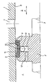
- a cross section through a pneumatic directional control valve is illustrated in the drawing.
- a piston 2 is arranged displaceably in the direction of the double arrow A, which indicates the stroke movement.
- the piston 2 is made in one piece with a rod 3. It divides the interior of the cylinder 1 into two subspaces 4 and 5. Depending on the position of the piston, one of these subspaces can be connected to a connection channel 7 provided in the cylinder wall.
- a mechanical seal 9 is inserted into a groove 8 of the piston 2.
- an O-ring 10 is arranged, which is seated in an annular groove 11, which is connected to the subspace 4 via a bore 12.
- the overpressure P prevailing in the partial space 4 thus also acts on the inside of the O-ring 10. Under the action of the pressure, this O-ring presses the mechanical seal 9 against the cylinder wall 6. This mechanical seal is subject to wear due to abrasion and / or contamination . It is then adjusted by the widening O-ring 10, the extent of this adjustment being able to be influenced by the choice of the cord thickness of the O-ring.
- the mechanical seal 9 consists of a plastic material that has sufficient flow properties so that the mechanical seal lies sealingly against the cylinder wall. This flow, however, has the undesirable effect that the mechanical seal yields when the connecting duct 7 is passed over and gets caught there or is at least exposed to increased wear. Therefore, only schematically indicated glass fibers 13 are inserted or incorporated into the mechanical seal 9 here. These glass fibers give the mechanical seal sufficient rigidity and inertia so that it cannot give way when the connection channel 7 is passed over. On the other hand, they do not prevent the long-term flow of the plastic, which is necessary to achieve a good seal against the cylinder wall.
- the mechanical seal thus has flow properties in the long term, while its short-term behavior is stiff. This is also desirable since in the normal position the piston 2 is positioned to the left or right of the connection channel 7, where flow is desired, while driving over this connection channel only takes a short time, in which the glass fibers ensure the rigidity of the mechanical seal.
- the glass fibers 13 can of course not only be incorporated into the mechanical seal in the circumferential direction, as shown in the exemplary embodiment, but can also extend in the radial or axial direction.
- this undercut reduces the friction surface of the mechanical seal against the cylinder wall, which reduces wear.
Landscapes
- Engineering & Computer Science (AREA)
- General Engineering & Computer Science (AREA)
- Mechanical Engineering (AREA)
- Physics & Mathematics (AREA)
- Architecture (AREA)
- Fluid Mechanics (AREA)
- Sealing Devices (AREA)
- Pistons, Piston Rings, And Cylinders (AREA)
- Actuator (AREA)
Description
- Die Erfindung betrifft eine Kolbendichtung entsprechend dem Oberbegriff des Patentanspruches.
- Eine Kolbendichtung entsprechend dem Oberbegriff des Patentanspruches ist beispielsweise durch die FR-A-2 410 771 bekannt. Hierbei sind die aus mehreren Kolbenringen bestehende Gleitringdichtung und der elastisch verformbare Ring in einer gemeinsamen Ringnut des Kolbens untergebracht. Die radiale Nachstellung der Gleitringdichtung bei Verschleiss der Kolbenringe erfolgt über die im Kolben vorgesehene Bohrung und den elastisch verformbaren Ring durch das in einer Zylinderkammer vorhandene Druckmittel. Wählt man die axiale Breite der Ringnut in Abhängigkeit von der axialen Stärke der vorgesehenen Gleitringdichtung, so ist damit auch die axiale Breite des elastisch verformbaren Ringes bestimmt.
- Der Erfindung liegt die Aufgabe zugrunde, eine Kolbendichtung entsprechend dem Oberbegriff des Patentanspruches so auszubilden, dass das Mass der Nachstellung der Gleitringdichtung (die einem Verschleiss durch Abrieb und/oder Verunreinigung unterliegt) beeinflusst werden kann.
- Diese Aufgabe wird erfindungsgemäss durch die kennzeichnenden Merkmale des Patentanspruches gelöst.
- Als Ausführungsbeispiel der Erfindung ist in der Zeichnung ein Querschnitt durch ein pneumatisches Wegeventil veranschaulicht.
- In einem mit 1 bezeichneten Zylinder ist ein Kolben 2 in Richtung des Doppelpfeiles A, der die Hubbewegung andeutet, verschiebbar angeordnet. Der Kolben 2 ist hier einstückig mit einer Stange 3 gearbeitet. Er teilt den Innenraum des Zylinders 1 in zwei Teilräume 4 und 5. Je nach Stellung des Kolbens kann einer dieser Teilräume mit einem in der Zylinderwand vorgesehenen Anschlusskanal 7 verbunden werden.
- In eine Nut 8 des Kolbens 2 ist eine Gleitringdichtung 9 eingesetzt. Auf der der Zylinderwand 6 abgewandten Seite dieser Gleitringdichtung ist ein O-Ring 10 angeordnet, der in einer Ringnut 11 sitzt, welche über eine Bohrung 12 mit dem Teilraum 4 in Verbindung steht.
- Der in dem Teilraum 4 herrschende Überdruck P wirkt somit auch auf die Innenseite des O-Rings 10. Unter der Einwirkung des Drucks presst dieser O-Ring die Gleitringdichtung 9 gegen die Zylinderwand 6. Diese Gleitringdichtung unterliegt einem Verschleiss durch Abrieb und/oder- Verunreinigung. Sie wird dann durch den sich aufweitenden O-Ring 10 nachgestellt, wobei das Mass dieser Nachstellung durch die Wahl der Schnurstärke des O-Rings beeinflusst werden kann.
- Die Gleitringdichtung 9 besteht aus einem Kunststoffmaterial, das ausreichende Fliesseigenschaften aufweist, so dass sich die Gleitringdichtung dichtend an die Zylinderwand anlegt. Dieses Fliessen hat indes den unerwünschten Effekt, dass die Gleitringdichtung beim Überfahren des Anschlusskanals 7 nachgibt und sich dort verhakt oder zumindest erhöhtem Verschleiss ausgesetzt ist. In die Gleitringdichtung 9 sind daher hier nur schematisch angedeutete Glasfasern 13 eingelegt oder eingearbeitet. Diese Glasfasern verleihen der Gleitringdichtung eine ausreichende Steifheit und Trägheit, so dass sie beim Überfahren des Anschlusskanals 7 nicht nachgeben kann. Sie verhindern andererseits jedoch nicht das langfristige Fliessen des Kunststoffes, welches nötig ist, um eine gute Abdichtung gegenüber der Zylinderwand zu erzielen.
- Die Gleitringdichtung weist somit langfristig gesehen Fliesseigenschaften auf, während ihr kurzfristiges Verhalten steif ist. Dies ist auch erwünscht, da in der normalen Stellung der Kolben 2 links oder rechts von dem Anschlusskanal 7 positioniert ist, wo Fliessen erwünscht ist, während das Überfahren dieses Anschlusskanals nur kurze Zeit beansprucht, in der die Glasfasern die Steifheit der Gleitringdichtung gewährleisten.
- Die Glasfasern 13 können natürlich nicht nur, wie im Ausführungsbeispiel gezeigt, in Umfangsrichtung in die Gleitringdichtung eingearbeitet sein, sondern können sich auch in radialer oder axialer Richtung erstrecken.
- Auf der der Zylinderwand 6 zugewandten Seite der Gleitringdichtung 9 ist diese weiterhin mit einem Freistich 14 versehen. Durch diesen Freistich verkleinert sich die Reibungsfläche der Gleitringdichtung gegenüber der Zylinderwand, wodurch der Verschleiss geringer wird.
Claims (1)
- Kolbendichtung, insbesondere für pneumatische Wegeventile und Zylinder,a) wobei in einer umlaufenden Nut (8) des Kolbens (2) eine aus Kunststoff bestehende Gleitringdichtung (9) angeordnet ist, die die Abdichtung gegenüber der Zylinderwand (6) gewährleistet,b) wobei ferner der Kolben an mindestens einer Stirnfläche mit wenigstens einer Bohrung (12) versehen ist, die mit der die Gleitringdichtung (9) aufnehmenden umlaufenden Nut (8) in Verbindung steht,c) und wobei ein elastisch verformbarer Ring (10) vorgesehen ist, der an der Innenseite der Gleitringdichtung (9) anliegt, gekennzeichnet durch folgende Merkmale:d) der als O-Ring ausgebildete, elastisch verformbare Ring (10) ist in einer die Kolbenbohrung (12) mit der umlaufenden Nut (8) verbindenden Ringnut (11) angeordnet, wobei die Schnurstärke des O-Ringes im Hinblick auf die Nachstellung der Gleitringdichtung (9) gewählt ist;e) die Gleitringdichtung (9) wird durch einen Gleitring gebildet, in dessen Kunststoffmasse Fasern aus härterem Material zur Erzielung einer ausreichenden Steifigkeit des Gleitringes eingebettet sind.
Applications Claiming Priority (2)
| Application Number | Priority Date | Filing Date | Title |
|---|---|---|---|
| DE3336209A DE3336209C2 (de) | 1983-10-05 | 1983-10-05 | Kolbendichtung |
| DE3336209 | 1983-10-05 |
Publications (3)
| Publication Number | Publication Date |
|---|---|
| EP0140052A2 EP0140052A2 (de) | 1985-05-08 |
| EP0140052A3 EP0140052A3 (en) | 1986-09-17 |
| EP0140052B1 true EP0140052B1 (de) | 1988-12-07 |
Family
ID=6211059
Family Applications (1)
| Application Number | Title | Priority Date | Filing Date |
|---|---|---|---|
| EP84110581A Expired EP0140052B1 (de) | 1983-10-05 | 1984-09-05 | Kolbendichtung |
Country Status (3)
| Country | Link |
|---|---|
| EP (1) | EP0140052B1 (de) |
| JP (1) | JPS6088275A (de) |
| DE (2) | DE3336209C2 (de) |
Cited By (1)
| Publication number | Priority date | Publication date | Assignee | Title |
|---|---|---|---|---|
| DE29717654U1 (de) * | 1997-10-02 | 1998-11-12 | Alusuisse Bayrisches Druckguß-Werk GmbH & Co. KG, 85570 Markt Schwaben | Kolben für einen Kolbenverdichter |
Families Citing this family (19)
| Publication number | Priority date | Publication date | Assignee | Title |
|---|---|---|---|---|
| DE3712331A1 (de) * | 1987-04-11 | 1988-10-27 | Ibm Deutschland | Vorrichtung zum abdichten einer luftkammer |
| DE4006257A1 (de) * | 1989-03-09 | 1990-09-20 | Busak & Luyken Gmbh & Co | Dichtungsanordnung fuer wellen |
| US5168895A (en) * | 1989-09-01 | 1992-12-08 | Richard Voss Grubenausbau Gmbh | Pressure-relief valve with teflon seal |
| DE4107083A1 (de) * | 1991-03-06 | 1992-09-10 | Teves Gmbh Alfred | Schieberventil |
| US5118449A (en) * | 1991-05-13 | 1992-06-02 | Glitsch, Inc. | Method of and apparatus for cartridge tray sealing |
| DE19708951A1 (de) | 1997-03-05 | 1998-09-24 | Uhp Corp | Hochdruckkolbendichtung |
| DE19907883A1 (de) * | 1999-02-24 | 2000-08-31 | Tox Pressotechnik Gmbh | Hydropneumatischer Druckübersetzer |
| DE10215492B3 (de) * | 2002-04-09 | 2004-02-12 | Busak + Shamban Gmbh | Dichtungsanordnung, insbesondere eines Luftfedersystems |
| DE10250070B4 (de) * | 2002-10-25 | 2007-01-04 | Carl Freudenberg Kg | Kolben |
| ITMI20040084A1 (it) * | 2004-01-22 | 2004-04-22 | Robur Spa | Valvola ad inversione ciclo di impianti di refrigerazione riscaldamento a pompa di calore ad assorbimento |
| JP2007205608A (ja) * | 2006-01-31 | 2007-08-16 | Sumitomo Heavy Ind Ltd | 蓄冷器式冷凍機 |
| DE102008051624B4 (de) * | 2008-10-02 | 2016-05-04 | Hydac Electronic Gmbh | Schieberventil |
| JP2011169421A (ja) * | 2010-02-19 | 2011-09-01 | Isuzu Motors Ltd | ピストンリング |
| DE102011112552B4 (de) * | 2011-09-06 | 2020-11-26 | Knorr-Bremse Systeme für Schienenfahrzeuge GmbH | Steuerventil für selbsttätige Druckluftbremsen mit Gleitführungsmitteln |
| US20140260956A1 (en) * | 2013-03-14 | 2014-09-18 | Woodward, Inc. | Circumferential sealing of piston assembly in a piston actuator |
| CN103277285A (zh) * | 2013-05-07 | 2013-09-04 | 安庆市佰联无油压缩机有限公司 | 往复活塞式气体压缩机专用活塞组件 |
| CN103982395A (zh) * | 2014-04-25 | 2014-08-13 | 珠海辉钰医疗科技有限公司 | 一种氧气增压机 |
| CN112032306B (zh) * | 2020-08-25 | 2022-10-25 | 西安近代化学研究所 | 一种环向不平整圆柱面用环向密封装置 |
| CN115773359B (zh) * | 2022-11-30 | 2026-04-17 | 南京高速齿轮制造有限公司 | 供油润滑装置、齿轮箱及供油润滑方法 |
Citations (1)
| Publication number | Priority date | Publication date | Assignee | Title |
|---|---|---|---|---|
| FR2410771A1 (fr) * | 1977-11-30 | 1979-06-29 | Festo Maschf Stoll G | Dispositif d'etancheite entre des pieces disposees concentriquement et deplacables axialement l'une relativement a l'autre |
Family Cites Families (8)
| Publication number | Priority date | Publication date | Assignee | Title |
|---|---|---|---|---|
| GB959910A (en) * | 1962-06-07 | 1964-06-03 | Garlock Inc | Improvements in or relating to wear rings for pistons |
| CH461203A (de) * | 1966-08-08 | 1968-08-15 | A Jacobellis Alphonse | Kolbenabdichtung für Druckspeicher |
| DE6811760U (de) * | 1968-12-17 | 1969-04-17 | Carl Freudenberg | Zolbendichtring |
| DE6937506U (de) * | 1969-09-24 | 1970-01-29 | Merkel Asbest & Gummiwerke | Gummielastischer, gewebeverstaerkter dichtring fuer einen ungeteilten kolben |
| JPS55129658A (en) * | 1979-03-29 | 1980-10-07 | Micron:Kk | Piston for compressor |
| JPS5610863A (en) * | 1979-06-30 | 1981-02-03 | Akio Nakano | Piston ring |
| DE2947895C2 (de) * | 1979-11-28 | 1982-03-18 | Hunger, Walter, 8700 Würzburg | Dichtungsanordnung bei einem Schwimmkolben |
| GB2115518A (en) * | 1982-02-16 | 1983-09-07 | John Harbidge | Sealing means |
-
1983
- 1983-10-05 DE DE3336209A patent/DE3336209C2/de not_active Expired
-
1984
- 1984-09-05 DE DE8484110581T patent/DE3475557D1/de not_active Expired
- 1984-09-05 EP EP84110581A patent/EP0140052B1/de not_active Expired
- 1984-09-11 JP JP59190451A patent/JPS6088275A/ja active Pending
Patent Citations (1)
| Publication number | Priority date | Publication date | Assignee | Title |
|---|---|---|---|---|
| FR2410771A1 (fr) * | 1977-11-30 | 1979-06-29 | Festo Maschf Stoll G | Dispositif d'etancheite entre des pieces disposees concentriquement et deplacables axialement l'une relativement a l'autre |
Cited By (1)
| Publication number | Priority date | Publication date | Assignee | Title |
|---|---|---|---|---|
| DE29717654U1 (de) * | 1997-10-02 | 1998-11-12 | Alusuisse Bayrisches Druckguß-Werk GmbH & Co. KG, 85570 Markt Schwaben | Kolben für einen Kolbenverdichter |
Also Published As
| Publication number | Publication date |
|---|---|
| JPS6088275A (ja) | 1985-05-18 |
| EP0140052A3 (en) | 1986-09-17 |
| EP0140052A2 (de) | 1985-05-08 |
| DE3336209C2 (de) | 1985-08-14 |
| DE3336209A1 (de) | 1985-05-02 |
| DE3475557D1 (en) | 1989-01-12 |
Similar Documents
| Publication | Publication Date | Title |
|---|---|---|
| EP0140052B1 (de) | Kolbendichtung | |
| DE69025344T2 (de) | Zylinder-Kolben-Vorrichtung | |
| DE2311201A1 (de) | Stossdaempfer | |
| EP0670964A1 (de) | Ventil, insbesondere druckventil für eine radialkolbenpumpe, mit wenigen komponenten. | |
| DE2157194A1 (de) | Steuervorrichtung für Strömungsventile | |
| DE3920293C2 (de) | ||
| DE3404095C2 (de) | Kolben für einen Arbeitszylinder | |
| DE2343675A1 (de) | Regelventilanordnung fuer ein stroemungsmittel | |
| DE4429156C2 (de) | Pneumatikzylinder mit Dämpfungsmechanismus | |
| DE29519232U1 (de) | Kniehebelspannvorrichtung | |
| DE2240980A1 (de) | Einrichtung zur daempfung des kolbenaufschlages in hydraulischen arbeitszylindern | |
| DE2431135A1 (de) | Mehrwegeventil | |
| DE1043739B (de) | Absperreinrichtung fuer stroemende Medien | |
| DE4119402C2 (de) | Schieberventil | |
| DE1455227A1 (de) | Hydraulische Pressluft-Stossfangvorrichtung | |
| DE2430573A1 (de) | Nachstellbare fuehrungs- und dichtungsvorrichtung | |
| EP1975478B1 (de) | Dichtelement und Dichtungsanordnung damit | |
| DE2920369A1 (de) | Vorrichtung zur daempfung eines kolbens bei erreichen einer endstellung | |
| DE8105898U1 (de) | Kolben-Zylinder-Aggregat | |
| DE3725558C1 (en) | Hydraulic or pneumatic actuator - has constant sealing gap between piston and housing | |
| DE3132430C2 (de) | Arbeitszylinder für pneumatische oder hydraulische Arbeitsmedien | |
| AT239618B (de) | Druckabhängig schaltendes Dreiwegeventil | |
| DE1123164B (de) | Hydraulischer Stossdaempfer | |
| DE69302873T2 (de) | Hydraulisches Hochleistungsstellglied mit Spielregelung | |
| AT228580B (de) | Selbsttätiges Absperrventil mit Fernbetätigungseinrichtung |
Legal Events
| Date | Code | Title | Description |
|---|---|---|---|
| PUAI | Public reference made under article 153(3) epc to a published international application that has entered the european phase |
Free format text: ORIGINAL CODE: 0009012 |
|
| AK | Designated contracting states |
Designated state(s): DE FR GB IT |
|
| PUAL | Search report despatched |
Free format text: ORIGINAL CODE: 0009013 |
|
| AK | Designated contracting states |
Kind code of ref document: A3 Designated state(s): DE FR GB IT |
|
| 17P | Request for examination filed |
Effective date: 19870227 |
|
| 17Q | First examination report despatched |
Effective date: 19880122 |
|
| GRAA | (expected) grant |
Free format text: ORIGINAL CODE: 0009210 |
|
| AK | Designated contracting states |
Kind code of ref document: B1 Designated state(s): DE FR GB IT |
|
| REF | Corresponds to: |
Ref document number: 3475557 Country of ref document: DE Date of ref document: 19890112 |
|
| ITF | It: translation for a ep patent filed | ||
| GBT | Gb: translation of ep patent filed (gb section 77(6)(a)/1977) | ||
| ET | Fr: translation filed | ||
| PLBI | Opposition filed |
Free format text: ORIGINAL CODE: 0009260 |
|
| 26 | Opposition filed |
Opponent name: FESTO KG Effective date: 19890708 |
|
| PG25 | Lapsed in a contracting state [announced via postgrant information from national office to epo] |
Ref country code: GB Effective date: 19890905 |
|
| GBPC | Gb: european patent ceased through non-payment of renewal fee | ||
| REG | Reference to a national code |
Ref country code: FR Ref legal event code: ST |
|
| RDAG | Patent revoked |
Free format text: ORIGINAL CODE: 0009271 |
|
| STAA | Information on the status of an ep patent application or granted ep patent |
Free format text: STATUS: PATENT REVOKED |
|
| 27W | Patent revoked |
Effective date: 19900518 |
|
| GBPR | Gb: patent revoked under art. 102 of the ep convention designating the uk as contracting state |