EP0140100A2 - Foldable tarpaulin - Google Patents
Foldable tarpaulin Download PDFInfo
- Publication number
- EP0140100A2 EP0140100A2 EP84110917A EP84110917A EP0140100A2 EP 0140100 A2 EP0140100 A2 EP 0140100A2 EP 84110917 A EP84110917 A EP 84110917A EP 84110917 A EP84110917 A EP 84110917A EP 0140100 A2 EP0140100 A2 EP 0140100A2
- Authority
- EP
- European Patent Office
- Prior art keywords
- tarpaulin
- stiffeners
- roof
- fold line
- rectangular rigid
- Prior art date
- Legal status (The legal status is an assumption and is not a legal conclusion. Google has not performed a legal analysis and makes no representation as to the accuracy of the status listed.)
- Granted
Links
- 239000003351 stiffener Substances 0.000 claims abstract description 22
- 239000004744 fabric Substances 0.000 claims description 2
- 238000003466 welding Methods 0.000 claims 1
- 230000008719 thickening Effects 0.000 description 4
- 238000000034 method Methods 0.000 description 1
Images


Classifications
-
- B—PERFORMING OPERATIONS; TRANSPORTING
- B60—VEHICLES IN GENERAL
- B60J—WINDOWS, WINDSCREENS, NON-FIXED ROOFS, DOORS, OR SIMILAR DEVICES FOR VEHICLES; REMOVABLE EXTERNAL PROTECTIVE COVERINGS SPECIALLY ADAPTED FOR VEHICLES
- B60J7/00—Non-fixed roofs; Roofs with movable panels, e.g. rotary sunroofs
- B60J7/02—Non-fixed roofs; Roofs with movable panels, e.g. rotary sunroofs of sliding type, e.g. comprising guide shoes
- B60J7/06—Non-fixed roofs; Roofs with movable panels, e.g. rotary sunroofs of sliding type, e.g. comprising guide shoes with non-rigid element or elements
- B60J7/061—Non-fixed roofs; Roofs with movable panels, e.g. rotary sunroofs of sliding type, e.g. comprising guide shoes with non-rigid element or elements sliding and folding
- B60J7/062—Non-fixed roofs; Roofs with movable panels, e.g. rotary sunroofs of sliding type, e.g. comprising guide shoes with non-rigid element or elements sliding and folding for utility vehicles
Definitions
- the invention relates to a foldable tarpaulin, consisting of roof surface, side surfaces and end faces.
- tarpaulins are intended to protect the transported goods from the weather.
- these tarpaulins must be removed. This is very tedious and lengthy, especially for large trucks, and usually cannot be done by the driver alone.
- a suitable device to make the tarpaulin easier to handle is e.g. B. a commercially available. Sliding frame. It is a scissor grid that runs on rollers under the tarpaulin and folds the tarpaulin together.
- the disadvantage here is that damage to the tarpaulin, which can come between the scissor bars when pushed together, is not excluded.
- Rectangular rigid surface elements (2) are attached to the roof tarpaulin in the area of the fold line (7) between the roof tarpaulin and side tarpaulin. These rigid surface elements (2) can, however, also be U-shaped, H-shaped or frame-shaped from strips or rods and form a rectangular rigid surface with the tarpaulin (see FIGS. 4-9).
- Stiffeners (3) are also attached to the side tarpaulins in the area of the fold line (7) between the roof and side tarpaulins transversely to this fold line (7), specifically to every second flexible zone in the roof tarpaulin.
- the transverse extent of these stiffeners (3) is equal to the longitudinal extent of the rectangular rigid surface elements (2) on the roof tarpaulin.
- These stiffeners (3) can be strip-shaped, L-shaped or triangular as a surface or frame (see Fig. 4-9). In the case of a triangular design, one leg lies parallel to a surface element (2) of the roof tarpaulin at the fold line (7) to the roof tarpaulin.
- both the surface elements (2) on the roof tarpaulin and the stiffeners (3) on the side tarpaulin are either placed in fabric pockets that are sewn, welded or glued to the tarpaulin and / or they are welded directly to the tarpaulin or glued.
- the surface elements (2) and the stiffeners (3) are advantageously always attached to the underside or inside of the tarpaulin.
- Thickenings (5) with eyelets (4) are attached to the underside (inside) of the tarpaulin between the rectangular, rigid surface elements (2) in the area of every second flexible zone, to which the stiffeners (3) of the side tarpaulins are also connected a rope (pulling device) (6) runs on both sides of the roof tarpaulin.
- These ropes (6) (2 pieces per tarpaulin) are firmly connected to the tarpaulin at one end of the tarpaulin or at the fold line to form an end face.
- the tarpaulin is unfolded or replaced by pulling on the ends of the cables (6) attached to the tarpaulin.
- the first and the last rectangular rigid surface element (2) on each side of the roof tarpaulin is about 10-20% longer than the rest, so that the entire tarpaulin package is supported by this first and last surface element in the folded state and cannot tip over .
- the tarpaulin (1) can be easily removed as a package from the body linkage and put back on again when folded.
Landscapes
- Mechanical Engineering (AREA)
- Engineering & Computer Science (AREA)
- Tents Or Canopies (AREA)
- Professional, Industrial, Or Sporting Protective Garments (AREA)
- Cartons (AREA)
- External Artificial Organs (AREA)
- Mechanical Pencils And Projecting And Retracting Systems Therefor, And Multi-System Writing Instruments (AREA)
- Bag Frames (AREA)
- Wrappers (AREA)
- Surface Acoustic Wave Elements And Circuit Networks Thereof (AREA)
- Special Chairs (AREA)
- Table Devices Or Equipment (AREA)
- Conveying And Assembling Of Building Elements In Situ (AREA)
- Roof Covering Using Slabs Or Stiff Sheets (AREA)
Abstract
In der Dachfläche befinden sich jeweils an der Knicklinie zur Seitenfläche über die gesamte Dachflächenlänge rechteckige steife Flächenelemente mit dazwischenliegenden biegsamen Zonen. In der jeweiligen Seitenfläche befinden sich an der Knicklinie zur Dachfläche Versteifungen quer zu dieser Knicklinie an jeder zweiten biegsamen Zone. Diese Versteifungen haben eine Quererstreckung gleich der Längserstreckung parallel zur Knicklinie der rechteckigen steifen Flächenelemente. An einem Ende der Dachfläche ist auf jeder Seite an der dort befindlichen biegsamen Zone je eine Zugvorrichtung befestigt, die durch Ösen an der Unterseite derjenigen biegsamen Zonen läuft, an denen sich die Versteifungen befinden. Mit Hilfe der Zugvorrichtung kann die Plane zusammengefaltet werden.
Description
Die Erfindung betrifft eine faltbare Plane, bestehend aus Dachfläche, Seitenflächen und Stirnflächen.The invention relates to a foldable tarpaulin, consisting of roof surface, side surfaces and end faces.
Planen, z. B. Lastwagenplanen, sollen das transportierte Gut vor Witterungseinflüssen schützen. Beim Laden grösserer Teile, z. B. mit einem Kran, müssen diese Planen entfernt werden. Dies ist vor allem bei großen Lastwagen sehr mühsam und langwierig und meist vom Fahrer alleine nicht zu machen.Planning, e.g. B. tarpaulins are intended to protect the transported goods from the weather. When loading larger parts, e.g. B. with a crane, these tarpaulins must be removed. This is very tedious and lengthy, especially for large trucks, and usually cannot be done by the driver alone.
Eine geeignete Vorrichtung, um die Plane leichter handhaben zu können, ist z. B. ein im Handel befindl. Schiebegestell. Dabei handelt es sich um ein Scherengitter, das unter der Dachplane auf Rollen läuft und durch Zusammenschieben die Plane faltet. Von Nachteil ist dabei daß Beschädigungen der Plane, die beim Zusammenschieben zwischen die Scherengitterstäbe kommen kann, nicht ausgeschlossen sind.A suitable device to make the tarpaulin easier to handle is e.g. B. a commercially available. Sliding frame. It is a scissor grid that runs on rollers under the tarpaulin and folds the tarpaulin together. The disadvantage here is that damage to the tarpaulin, which can come between the scissor bars when pushed together, is not excluded.
Es wurde gefunden, daß auch ohne aufwendige Vorrichtung ein schnelles und einfaches Falten und Entfernen der plane, die aus Dachfläche, zwei Seiten- und ein oder zwei Stirnflächen besteht, möglich ist.It has been found that quick and easy folding and removal of the tarpaulin, which consists of a roof surface, two side surfaces and one or two end surfaces, is possible even without a complex device.
An die Dachplane werden im Bereich der Knicklinie (7) zwischen Dach- und Seitenplane rechteckige steife Flächenelemente (2) angebracht. Diese steifen Flächenelemente (2) können aber auch aus Streifen oder Stäben U-förmig, H-förmig oder rahmenförmig sein und mit der Plane eine rechteckige steife Fläche bilden (siehe Fig. 4 - 9).Rectangular rigid surface elements (2) are attached to the roof tarpaulin in the area of the fold line (7) between the roof tarpaulin and side tarpaulin. These rigid surface elements (2) can, however, also be U-shaped, H-shaped or frame-shaped from strips or rods and form a rectangular rigid surface with the tarpaulin (see FIGS. 4-9).
Zwischen den einzelnen Flächenelementen bleiben jeweils biegsame Zonen.Flexible zones remain between the individual surface elements.
An die Seitenplanen werden ebenfalls im Bereich der Knicklinie (7) zwischen Dach- und Seitenplane quer zu dieser Knicklinie (7) Versteifungen (3) angebracht, und zwar an jede zweite biegsame Zone in der Dachplane anschließend. Die Quererstreckung dieser Versteifungen (3) ist gleich der Längserstreckung der rechteckigen steifen Flächenelemente (2) an der Dachplane. Diese Versteifungen (3) können streifen-(stab)förmig, L-förmig oder dreieckig als Fläche oder Rahmen ausgebildet sein (siehe Fig. 4-- 9). Bei dreieckiger Ausbildung liegt'jeweils ein Schenkel parallel zu einem Flächenelement (2) der Dachplane an der Knicklinie (7) zur Dachplane. Zwischen Versteifung (3) in der Seitenplane und Flächenelement (2) in der Dachplane verbleibt im Bereich der Knicklinie (7) wiederum eine biegsame-Stelle. Sowohl die Flächenelemente (2) an der Dachplane wie auch die Versteifungen (3) an der Seitenplane werden entweder in Gewebe-Taschen, die an die Plane genäht, geschweißt oder geklebt sind, eingebracht und/oder sie werden direkt an die Plane genäht, geschweißt oder geklebt.Stiffeners (3) are also attached to the side tarpaulins in the area of the fold line (7) between the roof and side tarpaulins transversely to this fold line (7), specifically to every second flexible zone in the roof tarpaulin. The transverse extent of these stiffeners (3) is equal to the longitudinal extent of the rectangular rigid surface elements (2) on the roof tarpaulin. These stiffeners (3) can be strip-shaped, L-shaped or triangular as a surface or frame (see Fig. 4-9). In the case of a triangular design, one leg lies parallel to a surface element (2) of the roof tarpaulin at the fold line (7) to the roof tarpaulin. Between the stiffening (3) in the side tarpaulin and the surface element (2) in the roof tarpaulin, a flexible point remains in the area of the fold line (7). Both the surface elements (2) on the roof tarpaulin and the stiffeners (3) on the side tarpaulin are either placed in fabric pockets that are sewn, welded or glued to the tarpaulin and / or they are welded directly to the tarpaulin or glued.
Die Flächenelemente (2) und die Versteifungen (3) werden vorteilhafterweise immer an der Unter- bzw. Innenseite der Plane angebracht.The surface elements (2) and the stiffeners (3) are advantageously always attached to the underside or inside of the tarpaulin.
Zwischen den rechteckigen steifen Flächenelementen (2) jeweils im Bereich jeder zweiten biegsamen Zone, an die auch jeweils die Verteifungen (3) der Seitenplane anschließen, sind an der Unterseite (Innenseite) der Plane Verdickungen (5) mit Ösen (4) angebracht, durch die auf beiden Seiten der Dachplane je ein Seil (Zugvorrichtung) (6) läuft. Diese Seile (6) (pro Plane 2 Stück) sind jeweils an einem Planenende bzw. an der Knicklinie zu einer Stirnfläche mit der Plane fest verbunden.Thickenings (5) with eyelets (4) are attached to the underside (inside) of the tarpaulin between the rectangular, rigid surface elements (2) in the area of every second flexible zone, to which the stiffeners (3) of the side tarpaulins are also connected a rope (pulling device) (6) runs on both sides of the roof tarpaulin. These ropes (6) (2 pieces per tarpaulin) are firmly connected to the tarpaulin at one end of the tarpaulin or at the fold line to form an end face.
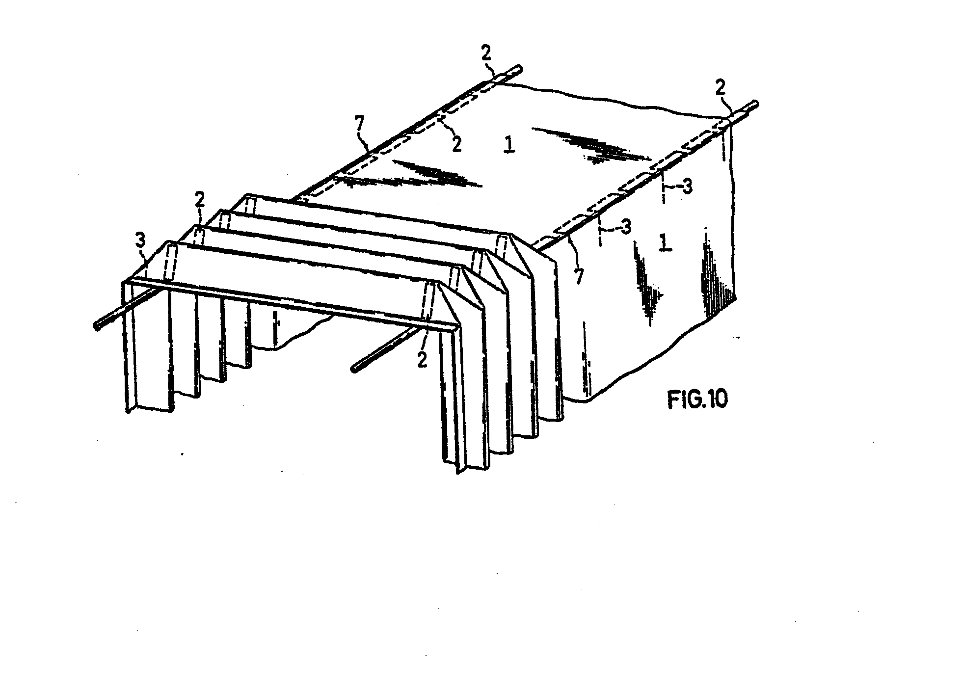
Im Bereich jeder biegsamen Zone, die nicht an die Versteifungen (3) an der Seitenplane anschließt, wird unterhalb der Plane eine Verdickung (5) angebracht, die, sobald an den Seilen (6) gezogen wird, die Faltung in der richtigen Richtung vorgibt und somit den Faltvorgang der Plane·(1) erleichtert. Wird an den Seilen (6) weitergezogen, so richten sich die rechteckigen steifen Flächenelemente (2) durch gegenseitiges Abstützen je zwei und zwei dachförmig auf und die Versteifung (3) in den Seitenplanen, die zunächst mit den Seitenplanen senkrecht hängen, stellen sich seitlich waagerecht ab. Die Plane faltet sich dabei korrekt in der Art eines Faltenbalges zu einem Paket. (Fig. 10)In the area of each flexible zone that does not connect to the stiffeners (3) on the side tarpaulin below the tarpaulin there is a thickening (5) which, as soon as the ropes (6) are pulled, specifies the folding in the correct direction and thus facilitates the folding process of the tarpaulin · (1). If the ropes (6) are pulled further, the rectangular, rigid surface elements (2) are erected by two supports, two roof-like, and the stiffening (3) in the side tarpaulins, which initially hang vertically with the side tarpaulins, is horizontally on the side from. The tarpaulin folds correctly in the manner of a bellows into a package. (Fig. 10)
Das Entfalten bzw. Wiederauflegen der Plane geschieht durch Ziehen an den an der Plane befestigten Enden der Seile (6). Vorteilhafterweise ist das erste und das letzte rechteckige steife Flächenelement (2) auf jeder Seite der Dachplane um etwa 10 - 20 % länger als die übrigen, so daß das gesamte Planenpaket in gefaltetem Zustand von diesem ersten'und letzten Flächenelement abgestützt wird und nicht umkippen kann. Die Plane (1) kann in gefaltetem Zustand auf einfache Weise als Paket von dem Aufbaugestänge abgenommen und wieder aufgelegt werden.The tarpaulin is unfolded or replaced by pulling on the ends of the cables (6) attached to the tarpaulin. Advantageously, the first and the last rectangular rigid surface element (2) on each side of the roof tarpaulin is about 10-20% longer than the rest, so that the entire tarpaulin package is supported by this first and last surface element in the folded state and cannot tip over . The tarpaulin (1) can be easily removed as a package from the body linkage and put back on again when folded.
Die folgenden Figuren erläutern die Erfindung.The following figures explain the invention.
Es stellen dar:
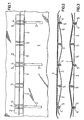
- Fig. 1 Planenausschnitt von unten (innen) gesehen in flachliegendem Zustand.
- Fig. 2 Schnitt durch die Plane (1) im Bereich der Zugvorrichtung (6) mit Seilführung unterhalb der rechteckigen steifen Flächenelemente (2) mit schlaffem Seil (6).
- Fig. 3 wie Fig. 2, jedoch gespanntes Seil (6) zu Be- .ginn der Faltung.
- Fig. 4 Beispielsweise Ausführung der rechteckigen steifen Flächenelemente (2) als Rahmen und der Versteifungen (3) als Stäbe.
- Fig. 5 Beispielsweise Ausführung der rechteckigen steifen Flächenelemente (2) als Rahmen und der Versteifungen (3) als Dreieckrahmen.
- Fig. 6 Beispielsweise Ausführung der rechteckigen steifen Flächenelemente (2) als Z-förmiger Stab und der Versteifungen (3) als Doppelstab.
- Fig. 7 Beispielsweise Ausführung der rechteckigen steifen Flächenelemente (2) als U-förmiger .Stab und der Versteifungen (3) als L-förmiger Stab.
- Fig. 8 Beispielsweise Ausführung der rechteckigen steifen Flächenelemente (2) als H-förmiger Stab und der Versteifungen (3) als L-förmiger Stab.
- Fig. 9 Beispielsweise Ausführung der rechteckigen steifen Flächenelemente (2) als rechteckige Platte und der Versteifungen (3) als dreieckige Platte.
- Fig. 10 Plane aufgelegt und teilweise gefaltet.
- Fig. 1 tarpaulin section seen from below (inside) in a flat state.
- Fig. 2 section through the tarpaulin (1) in the area of the pulling device (6) with a rope guide underneath the rectangular rigid surface elements (2) with a slack rope (6).
- Fig. 3 as Fig. 2, but tensioned rope (6) at the beginning of the folding.
- Fig. 4 For example, execution of the rectangular rigid surface elements (2) as a frame and the stiffeners (3) as rods.
- Fig. 5 For example, execution of the rectangular rigid surface elements (2) as a frame and the stiffeners (3) as a triangular frame.
- Fig. 6 For example, execution of the rectangular rigid surface elements (2) as a Z-shaped rod and the stiffeners (3) as a double rod.
- Fig. 7 For example, execution of the rectangular rigid surface elements (2) as a U-shaped .Bar and the stiffeners (3) as an L-shaped bar.
- Fig. 8 For example, execution of the rectangular rigid surface elements (2) as an H-shaped rod and the stiffeners (3) as an L-shaped rod.
- Fig. 9 For example, execution of the rectangular rigid surface elements (2) as a rectangular plate and the stiffeners (3) as a triangular plate.
- Fig. 10 tarpaulin placed and partially folded.
In den Figuren bedeutet: 1 Plane,-2 rechteckige steife Flächenelemente, 3 Versteifungen, 4 Ösen, 5 Verdickungen, 6 Zugvorrichtung (Seil), 7 Knicklinie zwischen Dach- und Seitenplane.In the figures: 1 tarpaulin, -2 rectangular rigid surface elements, 3 stiffeners, 4 eyelets, 5 thickenings, 6 pulling device (rope), 7 fold line between roof and side tarpaulin.
In den Figuren 4 - 10 sind der besseren Übersicht halber die Verdickungen 5 nicht eingezeichnet.For the sake of clarity, the
Claims (3)
daß sich in der Dachfläche jeweils an der Knicklinie zur Seitenfläche über die gesamte Dachflächenlänge rechteckige steife Flächenelemente mit dazwischenliegenden biegsamen Zonen befinden, und daß sich in der jeweiligen Seitenfläche, an der Knicklinie'zur Dachfläche Versteifungen quer zu dieser Knicklinie an jeder zweiten biegsamen Zone befinden, wobei .die Versteifungen eine Quererstreckung gleich der Längserstreckung der rechteckigen steifen Flächenelemente parallel zur Knicklinie haben, und daß an einem Ende der Dachfläche auf jeder Seite an der dort. befindlichen biegsamen Zone je eine Zugvorrichtung befestigt ist, die durch ösen an der Unterseite derjenigen biegsamen Zonen läuft, an denen sich die Versteifungen befinden, wobei die Plane mit Hilfe der Zugvorrichtung zusammengefaltet werden kann.1. Foldable tarpaulin, consisting of roof surface, side surfaces and one or two end surface (s), characterized in that
that in the roof surface there are rectangular rigid surface elements with flexible zones lying between them at the fold line to the side surface over the entire length of the roof surface, and that in the respective side surface at the fold line to the roof surface there are stiffeners transverse to this fold line at every second flexible zone, the stiffeners have a transverse extension equal to the longitudinal extension of the rectangular rigid surface elements parallel to the crease line, and that at one end of the roof surface on each side there. located flexible zone, a pulling device is attached, which runs through eyelets on the underside of those flexible zones on which the stiffeners are located, the tarpaulin can be folded up with the aid of the pulling device.
Priority Applications (1)
| Application Number | Priority Date | Filing Date | Title |
|---|---|---|---|
| AT84110917T ATE52466T1 (en) | 1983-09-21 | 1984-09-13 | FOLDABLE TARP. |
Applications Claiming Priority (2)
| Application Number | Priority Date | Filing Date | Title |
|---|---|---|---|
| DE19833334083 DE3334083A1 (en) | 1983-09-21 | 1983-09-21 | FOLDABLE PLAN |
| DE3334083 | 1983-09-21 |
Publications (3)
| Publication Number | Publication Date |
|---|---|
| EP0140100A2 true EP0140100A2 (en) | 1985-05-08 |
| EP0140100A3 EP0140100A3 (en) | 1988-04-20 |
| EP0140100B1 EP0140100B1 (en) | 1990-05-09 |
Family
ID=6209665
Family Applications (1)
| Application Number | Title | Priority Date | Filing Date |
|---|---|---|---|
| EP84110917A Expired - Lifetime EP0140100B1 (en) | 1983-09-21 | 1984-09-13 | Foldable tarpaulin |
Country Status (5)
| Country | Link |
|---|---|
| EP (1) | EP0140100B1 (en) |
| AT (1) | ATE52466T1 (en) |
| DE (2) | DE3334083A1 (en) |
| DK (1) | DK163287C (en) |
| NO (1) | NO160066C (en) |
Cited By (6)
| Publication number | Priority date | Publication date | Assignee | Title |
|---|---|---|---|---|
| GB2222118A (en) * | 1988-08-25 | 1990-02-28 | John Nadin | Retractable cover for load carrying vehicle |
| DE29608103U1 (en) * | 1996-05-07 | 1996-08-01 | Lenneper Decken- u. Zeltefabrik Albert Moll & Comp. GmbH & Co. KG, 42897 Remscheid | Vehicle body for trucks and trailers or the like. commercial vehicles |
| EP0890465A3 (en) * | 1997-07-08 | 2000-05-31 | Severino Donà | Connecting device for arcs of accordion-coverings and covering including said device |
| FR2883321A1 (en) * | 2005-03-18 | 2006-09-22 | Libner Sa Sa | Light roof for e.g. veranda, has roof units and frontage kinematically integrated in displacement and coupled by assembling nodes with pivot to simultaneously open roof and frontage which passes from high to low blocking position |
| ES2364363A1 (en) * | 2009-01-13 | 2011-09-01 | Adaico, S.L | Canvas for closing truck boxes or trailers. (Machine-translation by Google Translate, not legally binding) |
| RU184298U1 (en) * | 2018-07-12 | 2018-10-22 | Евгений Станиславович Фокин | SLIDING-SLIDING FOKIN FRAME FOR TENT OF THE BODY AND TRAILER OF THE CAR |
Families Citing this family (4)
| Publication number | Priority date | Publication date | Assignee | Title |
|---|---|---|---|---|
| DE20214009U1 (en) | 2002-09-11 | 2003-02-13 | Sommer Fahrzeugbau GmbH & Co. KG, 33649 Bielefeld | Folding tarpaulin wall for load compartment of e.g. lorry, has elastic tensile part secured to tarpaulin guide bars and folding parts |
| DE202012104195U1 (en) | 2012-11-02 | 2013-02-11 | Iws Gmbh | Commercial vehicle body with at least one side tarpaulin |
| DE102014115652A1 (en) * | 2014-10-28 | 2016-04-28 | Fahrzeugbau Heinz Böse GmbH | Construction of a commercial vehicle |
| DE102015111842B4 (en) * | 2015-07-21 | 2018-07-05 | Iws Gmbh | Container superstructure |
Family Cites Families (4)
| Publication number | Priority date | Publication date | Assignee | Title |
|---|---|---|---|---|
| DE1455743B2 (en) * | 1965-08-11 | 1976-10-14 | Dr.Ing.H.C. F. Porsche Ag, 7000 Stuttgart | TOP FOR MOTOR VEHICLES |
| US3400973A (en) * | 1966-04-28 | 1968-09-10 | Herou Lars Borje Svante | Superstructure for load vehicles |
| DE2841791A1 (en) * | 1978-09-26 | 1980-04-03 | Daimler Benz Ag | Compact sliding or folding roof for car - consists of double skin and sliding struts giving concertina shape when folded |
| DE8103249U1 (en) * | 1981-02-07 | 1981-07-30 | Adorno + Leisentritt Fahrzeugbau Gmbh, 4712 Werne | "COVER FOR THE LOADING AREA OF A COMMERCIAL VEHICLE" |
-
1983
- 1983-09-21 DE DE19833334083 patent/DE3334083A1/en not_active Withdrawn
-
1984
- 1984-09-13 DE DE8484110917T patent/DE3482178D1/en not_active Expired - Lifetime
- 1984-09-13 EP EP84110917A patent/EP0140100B1/en not_active Expired - Lifetime
- 1984-09-13 AT AT84110917T patent/ATE52466T1/en not_active IP Right Cessation
- 1984-09-20 NO NO843759A patent/NO160066C/en not_active IP Right Cessation
- 1984-09-20 DK DK448984A patent/DK163287C/en active
Cited By (7)
| Publication number | Priority date | Publication date | Assignee | Title |
|---|---|---|---|---|
| GB2222118A (en) * | 1988-08-25 | 1990-02-28 | John Nadin | Retractable cover for load carrying vehicle |
| DE29608103U1 (en) * | 1996-05-07 | 1996-08-01 | Lenneper Decken- u. Zeltefabrik Albert Moll & Comp. GmbH & Co. KG, 42897 Remscheid | Vehicle body for trucks and trailers or the like. commercial vehicles |
| EP0890465A3 (en) * | 1997-07-08 | 2000-05-31 | Severino Donà | Connecting device for arcs of accordion-coverings and covering including said device |
| FR2883321A1 (en) * | 2005-03-18 | 2006-09-22 | Libner Sa Sa | Light roof for e.g. veranda, has roof units and frontage kinematically integrated in displacement and coupled by assembling nodes with pivot to simultaneously open roof and frontage which passes from high to low blocking position |
| ES2364363A1 (en) * | 2009-01-13 | 2011-09-01 | Adaico, S.L | Canvas for closing truck boxes or trailers. (Machine-translation by Google Translate, not legally binding) |
| RU2527877C2 (en) * | 2009-01-13 | 2014-09-10 | Адайко, С.Л. | Canopy for trucks or trailers |
| RU184298U1 (en) * | 2018-07-12 | 2018-10-22 | Евгений Станиславович Фокин | SLIDING-SLIDING FOKIN FRAME FOR TENT OF THE BODY AND TRAILER OF THE CAR |
Also Published As
| Publication number | Publication date |
|---|---|
| NO160066B (en) | 1988-11-28 |
| NO843759L (en) | 1985-03-22 |
| DK163287B (en) | 1992-02-17 |
| DK448984D0 (en) | 1984-09-20 |
| DE3482178D1 (en) | 1990-06-13 |
| NO160066C (en) | 1989-03-08 |
| DK448984A (en) | 1985-03-22 |
| EP0140100A3 (en) | 1988-04-20 |
| DE3334083A1 (en) | 1985-04-18 |
| EP0140100B1 (en) | 1990-05-09 |
| ATE52466T1 (en) | 1990-05-15 |
| DK163287C (en) | 1992-07-13 |
Similar Documents
| Publication | Publication Date | Title |
|---|---|---|
| DE7915936U1 (en) | FRONT SLIDE, ESPECIALLY FOR PARALLEL CLAMPING ARMS OR THE LIKE | |
| EP0140100B1 (en) | Foldable tarpaulin | |
| DE2829484A1 (en) | FILTER ARRANGEMENT | |
| DE2227849A1 (en) | EQUIPMENT FOR EXTENDING AND / OR READING MOTOR VEHICLES | |
| DE3247093C2 (en) | Tarpaulin frame for vehicles with quickly removable tarpaulins | |
| DE2046827C3 (en) | Holder for prefabricated large-area individual filter sheets in horizontal sheet filter presses with large-dimensioned filter elements | |
| DE2946699A1 (en) | PLANE, ESPECIALLY FOR AWNINGS | |
| DE6945673U (en) | SQUARE HALL ROOF | |
| DE2512275C3 (en) | Support frame for the transport of electrical units, machine units or the like. Resources | |
| CH657584A5 (en) | Corner connection element | |
| DE2423004C2 (en) | Device for securing cargo securing devices | |
| DE1955532C3 (en) | ||
| DE2013411C (en) | Foldable square hall roof | |
| AT66839B (en) | Collapsible tent, in particular for aircraft. | |
| AT275304B (en) | Method for applying strands of adhesive to the closable end of a cardboard box and cardboard box of rectangular cross-section for carrying out the method | |
| AT315731B (en) | Packing of laundry items and method of packing an item of laundry | |
| AT240833B (en) | Clamping device for a highly porous corrugated filter mat | |
| DE3025000C2 (en) | ||
| DE3622677A1 (en) | Device for winding webs, in particular cover sheets for vehicles | |
| DE2807480A1 (en) | Long item, e.g. metal rods, container - has base with two vertical supports each side with hooks at top | |
| DE20214009U1 (en) | Folding tarpaulin wall for load compartment of e.g. lorry, has elastic tensile part secured to tarpaulin guide bars and folding parts | |
| DE1856291U (en) | FORMWORK GIRDER FOR EXTENDING AND BUCKLING. | |
| DE7929294U1 (en) | Earthing contact bracket for multiple earthing contact sockets | |
| CH597903A5 (en) | Filter frame with beams of box-shaped profile with slots | |
| DE8508891U1 (en) | Conveyor belt cover |
Legal Events
| Date | Code | Title | Description |
|---|---|---|---|
| PUAI | Public reference made under article 153(3) epc to a published international application that has entered the european phase |
Free format text: ORIGINAL CODE: 0009012 |
|
| AK | Designated contracting states |
Designated state(s): AT BE CH DE FR GB IT LI LU NL SE |
|
| PUAL | Search report despatched |
Free format text: ORIGINAL CODE: 0009013 |
|
| AK | Designated contracting states |
Kind code of ref document: A3 Designated state(s): AT BE CH DE FR GB IT LI LU NL SE |
|
| 17P | Request for examination filed |
Effective date: 19880623 |
|
| 17Q | First examination report despatched |
Effective date: 19890227 |
|
| GRAA | (expected) grant |
Free format text: ORIGINAL CODE: 0009210 |
|
| AK | Designated contracting states |
Kind code of ref document: B1 Designated state(s): AT BE CH DE FR GB IT LI LU NL SE |
|
| REF | Corresponds to: |
Ref document number: 52466 Country of ref document: AT Date of ref document: 19900515 Kind code of ref document: T |
|
| ITF | It: translation for a ep patent filed | ||
| REF | Corresponds to: |
Ref document number: 3482178 Country of ref document: DE Date of ref document: 19900613 |
|
| ET | Fr: translation filed | ||
| GBT | Gb: translation of ep patent filed (gb section 77(6)(a)/1977) | ||
| PLBE | No opposition filed within time limit |
Free format text: ORIGINAL CODE: 0009261 |
|
| STAA | Information on the status of an ep patent application or granted ep patent |
Free format text: STATUS: NO OPPOSITION FILED WITHIN TIME LIMIT |
|
| 26N | No opposition filed | ||
| ITTA | It: last paid annual fee | ||
| EPTA | Lu: last paid annual fee | ||
| EAL | Se: european patent in force in sweden |
Ref document number: 84110917.6 |
|
| REG | Reference to a national code |
Ref country code: CH Ref legal event code: PUE Owner name: HOECHST AKTIENGESELLSCHAFT TRANSFER- ARTEVA TECHNO |
|
| NLS | Nl: assignments of ep-patents |
Owner name: ARTEVA TECHNOLOGIES S.A.R.L. |
|
| REG | Reference to a national code |
Ref country code: GB Ref legal event code: 732E |
|
| REG | Reference to a national code |
Ref country code: FR Ref legal event code: TP |
|
| PGFP | Annual fee paid to national office [announced via postgrant information from national office to epo] |
Ref country code: DE Payment date: 20000629 Year of fee payment: 17 |
|
| PGFP | Annual fee paid to national office [announced via postgrant information from national office to epo] |
Ref country code: NL Payment date: 20000703 Year of fee payment: 17 Ref country code: AT Payment date: 20000703 Year of fee payment: 17 |
|
| PGFP | Annual fee paid to national office [announced via postgrant information from national office to epo] |
Ref country code: SE Payment date: 20000704 Year of fee payment: 17 Ref country code: LU Payment date: 20000704 Year of fee payment: 17 Ref country code: GB Payment date: 20000704 Year of fee payment: 17 Ref country code: FR Payment date: 20000704 Year of fee payment: 17 |
|
| PGFP | Annual fee paid to national office [announced via postgrant information from national office to epo] |
Ref country code: CH Payment date: 20000706 Year of fee payment: 17 |
|
| PGFP | Annual fee paid to national office [announced via postgrant information from national office to epo] |
Ref country code: BE Payment date: 20000816 Year of fee payment: 17 |
|
| BECA | Be: change of holder's address |
Free format text: 20000126 *ARTEVA TECHNOLOGIES S.A.R.L.:TALSTRASSE 80, 8001 ZURICH |
|
| PG25 | Lapsed in a contracting state [announced via postgrant information from national office to epo] |
Ref country code: LU Free format text: LAPSE BECAUSE OF NON-PAYMENT OF DUE FEES Effective date: 20010913 Ref country code: GB Free format text: LAPSE BECAUSE OF NON-PAYMENT OF DUE FEES Effective date: 20010913 Ref country code: AT Free format text: LAPSE BECAUSE OF NON-PAYMENT OF DUE FEES Effective date: 20010913 |
|
| PG25 | Lapsed in a contracting state [announced via postgrant information from national office to epo] |
Ref country code: SE Free format text: LAPSE BECAUSE OF NON-PAYMENT OF DUE FEES Effective date: 20010914 |
|
| PG25 | Lapsed in a contracting state [announced via postgrant information from national office to epo] |
Ref country code: LI Free format text: LAPSE BECAUSE OF NON-PAYMENT OF DUE FEES Effective date: 20010930 Ref country code: CH Free format text: LAPSE BECAUSE OF NON-PAYMENT OF DUE FEES Effective date: 20010930 Ref country code: BE Free format text: LAPSE BECAUSE OF NON-PAYMENT OF DUE FEES Effective date: 20010930 |
|
| BERE | Be: lapsed |
Owner name: ARTEVA TECHNOLOGIES S.A.R.L. Effective date: 20010930 |
|
| PG25 | Lapsed in a contracting state [announced via postgrant information from national office to epo] |
Ref country code: NL Free format text: LAPSE BECAUSE OF NON-PAYMENT OF DUE FEES Effective date: 20020401 |
|
| GBPC | Gb: european patent ceased through non-payment of renewal fee |
Effective date: 20010913 |
|
| PG25 | Lapsed in a contracting state [announced via postgrant information from national office to epo] |
Ref country code: DE Free format text: LAPSE BECAUSE OF NON-PAYMENT OF DUE FEES Effective date: 20020501 |
|
| EUG | Se: european patent has lapsed |
Ref document number: 84110917.6 |
|
| REG | Reference to a national code |
Ref country code: CH Ref legal event code: PL |
|
| PG25 | Lapsed in a contracting state [announced via postgrant information from national office to epo] |
Ref country code: FR Free format text: LAPSE BECAUSE OF NON-PAYMENT OF DUE FEES Effective date: 20020531 |
|
| NLV4 | Nl: lapsed or anulled due to non-payment of the annual fee |
Effective date: 20020401 |
|
| REG | Reference to a national code |
Ref country code: FR Ref legal event code: ST |
|
| NLV4 | Nl: lapsed or anulled due to non-payment of the annual fee |
Effective date: 20020401 |