EP0140237A2 - Appareil pour faire des grillades - Google Patents
Appareil pour faire des grillades Download PDFInfo
- Publication number
- EP0140237A2 EP0140237A2 EP84112167A EP84112167A EP0140237A2 EP 0140237 A2 EP0140237 A2 EP 0140237A2 EP 84112167 A EP84112167 A EP 84112167A EP 84112167 A EP84112167 A EP 84112167A EP 0140237 A2 EP0140237 A2 EP 0140237A2
- Authority
- EP
- European Patent Office
- Prior art keywords
- troughs
- boundary plates
- plates
- boundary
- holding elements
- Prior art date
- Legal status (The legal status is an assumption and is not a legal conclusion. Google has not performed a legal analysis and makes no representation as to the accuracy of the status listed.)
- Withdrawn
Links
Images


Classifications
-
- A—HUMAN NECESSITIES
- A47—FURNITURE; DOMESTIC ARTICLES OR APPLIANCES; COFFEE MILLS; SPICE MILLS; SUCTION CLEANERS IN GENERAL
- A47J—KITCHEN EQUIPMENT; COFFEE MILLS; SPICE MILLS; APPARATUS FOR MAKING BEVERAGES
- A47J37/00—Baking; Roasting; Grilling; Frying
- A47J37/04—Roasting apparatus with movably-mounted food supports or with movable heating implements; Spits
- A47J37/047—Roasting apparatus with movably-mounted food supports or with movable heating implements; Spits with rotating drums or baskets
Definitions
- the invention relates to a device to be connected to a rotary grill drive for heating a grill item consisting of loose individual parts, which has a multi-part insert with receiving areas oriented longitudinally to a spit axis of rotation and rotationally symmetrical to the axis, the sides of which are open to the outside and can be closed by a basket cover.
- the invention has for its object to provide a device of the type mentioned, which allows loading with grilled food or emptying without the device having to be taken apart.
- the device should also have a simple structure and be much easier to handle compared to the prior art.
- the receiving areas of the insert consist of individual trays, which can be fixed on both sides to boundary plates of the device and that each receiving tray has a closable basket cover.
- the receiving trays of the device according to the invention can be loaded with grilled food independently of one another after opening their basket cover, or the grilled food can be removed from the trays after the heat has ended, without the device having to be removed from the grilling device. It is thus possible to prepare grilled food with different cooking times in the device, the finished grilled food can be removed from the pan after the grill drive has been interrupted, the pan can be reloaded if necessary and then grilled further. As can be seen from this, the existing grilling capacity can be optimally used in the device according to the invention.
- the troughs of the device can advantageously also be used as serving dishes for the finished food or as storage dishes, provided that the food is not to be consumed immediately. Further advantages are that the individual parts of the device are flat and not bulky, which makes cleaning them considerably easier. The parts of the device can also be easily assembled and disassembled, requiring little storage space when disassembled.
- a cylindrical shape is preferably provided as the shape for the device, in which the tubs with the food to be grilled are arranged on the periphery in a rotationally symmetrical manner with respect to the axis of rotation.
- Two tub arrangements have proven to be advantageous.
- a first arrangement in which the troughs are trapezoidal in cross-section and have push-in tabs on the side surfaces facing the boundary plates, the troughs form a polygonal rotating body.
- the second arrangement FIGS. 5 and 7
- cross-section-like troughs are provided which already specify the cylindrical shape of the device towards the outside.
- the boundary plates or designed the covers of the tubs.
- circular boundary plates are provided, which have rotationally symmetrical slots for the insertion tabs of the troughs and locking recesses for the holding elements of the covers on the plate periphery.
- Tabs and slots are advantageous plug connection parts between tubs and boundary plates. Because this type of connection is simple and the tabs on the tubs can be used as handle parts at the same time. The design of the device is not limited to this type of connection between the parts.
- polygonal boundary plates are provided which have contact surfaces for the tubs on the edge. It becomes polygonal understood that the base of the plates is a regular polygon, 'z. B. a quadrangle, pentagon, etc.
- the connection of the boundary plates to the tubs can be done as in the first arrangement via insertion webs on the contact surfaces. However, webs can also be provided on the contact surfaces, which laterally delimit the troughs, the actual cohesion of the parts only taking place after the skewer that connects the boundary plates to one another is established.
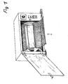
- a grill oven in which the baking space can be closed by a transparent door.
- a device 1 according to the invention for heating a grill item consisting of loose individual parts is suspended on a skewer inside the baking chamber and is driven by a motor of the grill oven (not shown). The device 1 rotates with the spit during the heating process, the contents being heated and baked by convection and / or radiant heat from a heat source in the oven.
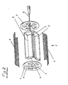
- the device 1 consists of receiving trays 2 for the grilled food, which are arranged in the device in a rotationally symmetrical manner about a longitudinal axis formed by a skewer 3, covers 4 made of stainless wire mesh for each tray 2 and two lateral boundary plates 5, which are connected by the spit 3.
- the device on the boundary plates 5 can also have stub axles which can be inserted into a corresponding drive device of the grill oven.
- the tubs 2, covers 4 and plates 5 form a cylindrical device body, the cylinder jacket of which is made of wire braid of the individual covers 4.
- a total of five elongated troughs 2 are provided in the device in FIG. 2, each of which has a trapezoidal cross section.
- the tubs 2 together form a prismatic body, the base of which is a regular pentagon.
- Tabs 6 are formed on the narrow sides of the troughs 2 and can be inserted into corresponding slots 7 in the boundary plates 5.
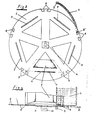
- Figure 3 the position of a tub 2 connected to a boundary plate 5 is indicated by dashed lines.
- the limiting plate 5 is circular in the embodiment according to FIGS. 2 and 3 and corresponds in diameter to the cylinder diameter of the device.
- the slots 7 are arranged at equal intervals along the side edges of a regular pentagon.
- the boundary plates 5 also have locking recesses 8 on their periphery, in which holding elements 9 and 9 'of the covers 4 can be fixed.
- the stub axles 9 on the upper edges of the cover 4 have a cylindrical handle part at their end, which makes it easier to open the cover and, when the cover is closed, serves as a lock which prevents the cover from moving laterally.
- the boundary plates 5 furthermore have in their middle adapted to the outer contours of the skewer 3, opposite bores with an attached closure part 10, via which the boundary plates 5 are fixed to the skewer 3 can be and thus cohesion of the device parts is achieved.
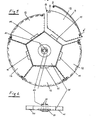
- boundary plates 15 are provided, the base of which is a regular pentagon.
- the boundary plates 15 are folded on the edge.
- the fold edges form contact surfaces for the receiving troughs 12 of the device, limiting webs 11 on the contact surfaces clamping the troughs 15 laterally when the device is assembled.
- the troughs 15 are designed in the form of a segment of a circle in cross section in this embodiment and, when assembled, form a drum-shaped body.
- a longitudinal edge of a tub 15 has a hook-shaped bar 13 which can be pushed over a strip-free longitudinal edge of an adjacent tub. As a result, the tubs 15 are interconnected.
- the latching recesses 8 for the holding elements 9 and 9 'of the tub cover 4 are now provided in the upper edge region of the narrow tub sides.
- the boundary plates 15 have a closure part 20, in which the plates 15 are fixed on the spit 3 in a simple manner via clamping webs 21.
- FIGS. 7 a and 7 b show a tub 12 of the device and schematically the possibility of connecting the tubs 12 to one another via the hook strips 13. If necessary, the edge of the tub 12 opposite the hook bar 13 can have a hooking bar (not shown) for the bar 13.
- connection tion variant between the tub and boundary plate 15 indicated.
- the trough 12 has slots 14 in the floor close to its narrow side surfaces, into which the webs 11 of the limiting plate 15 shown in FIG. 9 can be inserted.
- the boundary plates can also be connected by a connecting link 22 in addition to the spit 3, regardless of their design.
- the connecting rod 22 consists of a flat strip section which is folded at its ends. The fold ends of the connecting rod 22 have through openings for the skewer 3 and are hooked into plug-in tabs on the closure parts 10 of the boundary plates when the device is assembled, as indicated by arrows in FIG. 10. It is thus ensured that the parts of the device are held together even when the skewer 3 is pulled out.
Landscapes
- Engineering & Computer Science (AREA)
- Food Science & Technology (AREA)
- Baking, Grill, Roasting (AREA)
Applications Claiming Priority (2)
| Application Number | Priority Date | Filing Date | Title |
|---|---|---|---|
| DE19838329634 DE8329634U1 (de) | 1983-10-14 | 1983-10-14 | Vorrichtung zum erhitzen von grillgut |
| DE8329634U | 1983-10-14 |
Publications (2)
| Publication Number | Publication Date |
|---|---|
| EP0140237A2 true EP0140237A2 (fr) | 1985-05-08 |
| EP0140237A3 EP0140237A3 (fr) | 1985-06-05 |
Family
ID=6757978
Family Applications (1)
| Application Number | Title | Priority Date | Filing Date |
|---|---|---|---|
| EP84112167A Withdrawn EP0140237A3 (fr) | 1983-10-14 | 1984-10-11 | Appareil pour faire des grillades |
Country Status (2)
| Country | Link |
|---|---|
| EP (1) | EP0140237A3 (fr) |
| DE (1) | DE8329634U1 (fr) |
Cited By (6)
| Publication number | Priority date | Publication date | Assignee | Title |
|---|---|---|---|---|
| FR2682009A1 (fr) * | 1991-10-07 | 1993-04-09 | Thomaoglou Constant | Appareil de cuisson sans bain d'huile pour produits traditionnellement frits, ou autres produits alimentaires. |
| FR2772582A1 (fr) * | 1997-12-24 | 1999-06-25 | Francis Eliasse | Accessoire de tournebroche pour la cuisson des aliments |
| WO2001030220A1 (fr) * | 1999-10-28 | 2001-05-03 | Franklin Industries, L.L.C. | Appareil de cuisson au tournebroche |
| WO2001070084A3 (fr) * | 2000-03-23 | 2002-01-03 | Lekic Mirjana | Appareil combiné multifonctions pour préparation alimentaire |
| CN105455665A (zh) * | 2016-01-08 | 2016-04-06 | 项振双 | 电磁感应旋转式电磁炉烧烤器 |
| US10973236B2 (en) * | 2018-09-07 | 2021-04-13 | Deonarine Bassit | Automatic meat seasoning apparatus |
Family Cites Families (5)
| Publication number | Priority date | Publication date | Assignee | Title |
|---|---|---|---|---|
| DE370403C (de) * | 1923-03-02 | Emil Bleyer | Bratvorrichtung | |
| CH603130A5 (en) * | 1976-06-11 | 1978-08-15 | Therma Ag | Oven container for cooking bulk food |
| DE2811184A1 (de) * | 1978-03-15 | 1979-09-20 | Berg Sen | Vorrichtung zum erhitzen eines aus lockeren einzelteilen bestehenden grillgutes |
| FR2498915A1 (fr) * | 1981-02-04 | 1982-08-06 | Chaveron Louis | Tambour de cuisson pour aliments |
| US4437395A (en) * | 1982-04-02 | 1984-03-20 | Speaker Richard L | Spaghetti and food cooker |
-
1983
- 1983-10-14 DE DE19838329634 patent/DE8329634U1/de not_active Expired
-
1984
- 1984-10-11 EP EP84112167A patent/EP0140237A3/fr not_active Withdrawn
Cited By (8)
| Publication number | Priority date | Publication date | Assignee | Title |
|---|---|---|---|---|
| FR2682009A1 (fr) * | 1991-10-07 | 1993-04-09 | Thomaoglou Constant | Appareil de cuisson sans bain d'huile pour produits traditionnellement frits, ou autres produits alimentaires. |
| FR2772582A1 (fr) * | 1997-12-24 | 1999-06-25 | Francis Eliasse | Accessoire de tournebroche pour la cuisson des aliments |
| EP0925751A1 (fr) * | 1997-12-24 | 1999-06-30 | Francis Eliasse | Accessoire de tournebroche pour la cuisson des aliments |
| WO2001030220A1 (fr) * | 1999-10-28 | 2001-05-03 | Franklin Industries, L.L.C. | Appareil de cuisson au tournebroche |
| US6272975B1 (en) | 1999-10-28 | 2001-08-14 | Franklin Industries, Llc | Rotisserie cooking apparatus |
| WO2001070084A3 (fr) * | 2000-03-23 | 2002-01-03 | Lekic Mirjana | Appareil combiné multifonctions pour préparation alimentaire |
| CN105455665A (zh) * | 2016-01-08 | 2016-04-06 | 项振双 | 电磁感应旋转式电磁炉烧烤器 |
| US10973236B2 (en) * | 2018-09-07 | 2021-04-13 | Deonarine Bassit | Automatic meat seasoning apparatus |
Also Published As
| Publication number | Publication date |
|---|---|
| DE8329634U1 (de) | 1984-01-12 |
| EP0140237A3 (fr) | 1985-06-05 |
Similar Documents
| Publication | Publication Date | Title |
|---|---|---|
| DE2154748C2 (de) | Elektrischer Ofentoaster | |
| DE3432958A1 (de) | Grillgeraet | |
| DE4027555A1 (de) | Mikrowellenkochgeraet mit angetriebener ruehranordnung | |
| DE7433343U (de) | Drehbarer Grillkorb | |
| DE657089C (de) | Kuechengeraet zum Halten des zu bratenden, zu roestenden oder zu kochenden Fleisches oder sonstiger zuzubereitender Speisen in verschiedenen Lagen | |
| DE3000653A1 (de) | Transportable grillvorrichtung | |
| DE9116225U1 (de) | Vorrichtung zum Grillen von Bratgut | |
| EP0556698A2 (fr) | Support pour produits cuits ou grillés, en particulier pour volailles | |
| DE8329634U1 (de) | Vorrichtung zum erhitzen von grillgut | |
| DE3603848C1 (en) | Electric toaster | |
| DE2307575A1 (de) | Spiessgrillvorrichtung | |
| DE2759202A1 (de) | Grillgeraet mit mindestens einem kohlekasten | |
| DE2040077A1 (de) | Geraet zum Erhitzen von Speisen | |
| DE2641127B2 (de) | Grillgerät | |
| AT522693B1 (de) | Schneidemaschine | |
| DE2205562C3 (de) | Grilleinrichtung für Brat- und Backöfen mit mindestens einem Grillspieß | |
| EP0771165B1 (fr) | Panier utilise dans un four a air chaud pour la preparation d'aliments | |
| EP0275831A1 (fr) | Rôtissoire à usages multiples | |
| DE69205086T2 (de) | Kochgerät mit elektrischer Widerstandsheizung. | |
| DE102004001896B4 (de) | Einrichtung zum Grillen von Fleischspeisen | |
| DE102007053823B4 (de) | Vorrichtung zum Halten und Wenden von Nahrungsmitteln | |
| DE2811184A1 (de) | Vorrichtung zum erhitzen eines aus lockeren einzelteilen bestehenden grillgutes | |
| DE1404775A1 (de) | Grillgeraet | |
| DE2444163A1 (de) | Holzkohlengrillgeraet | |
| DE102004057098B4 (de) | Gargerät mit einer Haltevorrichtung für einen Grillspieß |
Legal Events
| Date | Code | Title | Description |
|---|---|---|---|
| PUAI | Public reference made under article 153(3) epc to a published international application that has entered the european phase |
Free format text: ORIGINAL CODE: 0009012 |
|
| PUAL | Search report despatched |
Free format text: ORIGINAL CODE: 0009013 |
|
| AK | Designated contracting states |
Designated state(s): AT BE CH DE FR GB IT LI NL SE |
|
| AK | Designated contracting states |
Designated state(s): AT BE CH DE FR GB IT LI NL SE |
|
| STAA | Information on the status of an ep patent application or granted ep patent |
Free format text: STATUS: THE APPLICATION IS DEEMED TO BE WITHDRAWN |
|
| 18D | Application deemed to be withdrawn |
Effective date: 19860206 |
|
| RIN1 | Information on inventor provided before grant (corrected) |
Inventor name: VAN DEN BERG, CHRISTIAAN |