EP0140245A2 - Seitentürscharniermechanismus eines Kraftfahrzeugs - Google Patents
Seitentürscharniermechanismus eines Kraftfahrzeugs Download PDFInfo
- Publication number
- EP0140245A2 EP0140245A2 EP84112234A EP84112234A EP0140245A2 EP 0140245 A2 EP0140245 A2 EP 0140245A2 EP 84112234 A EP84112234 A EP 84112234A EP 84112234 A EP84112234 A EP 84112234A EP 0140245 A2 EP0140245 A2 EP 0140245A2
- Authority
- EP
- European Patent Office
- Prior art keywords
- rotary
- side door
- vehicle body
- door
- hinge mechanism
- Prior art date
- Legal status (The legal status is an assumption and is not a legal conclusion. Google has not performed a legal analysis and makes no representation as to the accuracy of the status listed.)
- Granted
Links
Images


Classifications
-
- E—FIXED CONSTRUCTIONS
- E05—LOCKS; KEYS; WINDOW OR DOOR FITTINGS; SAFES
- E05D—HINGES OR SUSPENSION DEVICES FOR DOORS, WINDOWS OR WINGS
- E05D3/00—Hinges with pins
- E05D3/06—Hinges with pins with two or more pins
- E05D3/14—Hinges with pins with two or more pins with four parallel pins and two arms
- E05D3/145—Hinges with pins with two or more pins with four parallel pins and two arms specially adapted for vehicles
- E05D3/147—Hinges with pins with two or more pins with four parallel pins and two arms specially adapted for vehicles for vehicle doors
-
- E—FIXED CONSTRUCTIONS
- E05—LOCKS; KEYS; WINDOW OR DOOR FITTINGS; SAFES
- E05D—HINGES OR SUSPENSION DEVICES FOR DOORS, WINDOWS OR WINGS
- E05D15/00—Suspension arrangements for wings
- E05D15/28—Suspension arrangements for wings supported on arms movable in horizontal plane
-
- E—FIXED CONSTRUCTIONS
- E05—LOCKS; KEYS; WINDOW OR DOOR FITTINGS; SAFES
- E05D—HINGES OR SUSPENSION DEVICES FOR DOORS, WINDOWS OR WINGS
- E05D3/00—Hinges with pins
- E05D3/06—Hinges with pins with two or more pins
- E05D3/10—Hinges with pins with two or more pins with non-parallel pins
-
- E—FIXED CONSTRUCTIONS
- E05—LOCKS; KEYS; WINDOW OR DOOR FITTINGS; SAFES
- E05D—HINGES OR SUSPENSION DEVICES FOR DOORS, WINDOWS OR WINGS
- E05D15/00—Suspension arrangements for wings
- E05D15/28—Suspension arrangements for wings supported on arms movable in horizontal plane
- E05D15/32—Suspension arrangements for wings supported on arms movable in horizontal plane with two pairs of pivoted arms
-
- E—FIXED CONSTRUCTIONS
- E05—LOCKS; KEYS; WINDOW OR DOOR FITTINGS; SAFES
- E05Y—INDEXING SCHEME ASSOCIATED WITH SUBCLASSES E05D AND E05F, RELATING TO CONSTRUCTION ELEMENTS, ELECTRIC CONTROL, POWER SUPPLY, POWER SIGNAL OR TRANSMISSION, USER INTERFACES, MOUNTING OR COUPLING, DETAILS, ACCESSORIES, AUXILIARY OPERATIONS NOT OTHERWISE PROVIDED FOR, APPLICATION THEREOF
- E05Y2900/00—Application of doors, windows, wings or fittings thereof
- E05Y2900/50—Application of doors, windows, wings or fittings thereof for vehicles
- E05Y2900/53—Type of wing
- E05Y2900/531—Doors
Definitions
- This invention relates to improvements in side door hinge mechanism utilizing a quadric crank chain in a motor vehicle.
- the side door in a motor vehicle e.g. passenger car has heretofore been installed in a manner to be rotatable about a hinge affixed to a vehicle body for opening or closing.
- a door opening angle corresponding to the total length of the side door is required.
- a side door hinge mechanism in a motor vehicle, wherein a quadric crnak chain comprises: a rotary link 4 interconnecting a point on a vehicle body 2 and another point on a side door 3 on one side as rotary centers 2A and 3A out of four points including two points disposed on the vehicle body 2 and spaced apart from each other and two points disposed on the side door 3 and spaced apart from each other; a rotary link 5 interconnecting a point on the vehicle body 2 and another point on the side door 3 on the other side as rotary centers 2B and 3B; a portion between the two rotary centers 2A and 2B on the vehicle body 2; and another portion between the two rotary centers 3A and 3B on the side of the side door 3.
- a front pillar designated at 6 is a front pillar, 7 a front wheel and 8 a movable fender capable of rocking with the rotary link 4.
- a door glass 9 portion is considerably inclined and curved upwardly and inwardly in the widthwise direction of the vehicle body. Because of this, even if there is provided the aforesaid side door hinge mechanism utilizing the quadric crank chain, the top end portion of a door frame of the side door 3 or the top end portion of a door glass 9 interferes with an occupant 10 when the occupant gets on or off the vehicle, whereby the occupant 10 should decline his upper body, thereby presenting such a disadvantage that a satisfactory performance of getting on or off the vehicle cannot be secured.
- a quadric crank chain comprises: a first rotary link interconnecting points disposed on a vehicle body and a side door on one side as rotary center shafts out of four points including two points disposed on the vehicle body and spaced aprt from each other and two points disposed on the side door and spaced apart from each other; a second rotary link interconnecting points disposed on the vehicle body and the side door on the other side as rotary center shafts; a potion between the two points on the vehicle body; and another portion between the two points on the side door; the aforesaid four rotary center shafts are inclined relative to one anothr in such a manner that downward extensions of center axes of the four rotary center shafts intersect one another at one point.
- first and the second, rotary links consist of a plurality of rotary links having rotary centers on the extensions of the center axes and being similar in shape to each other.
- one of the first and the second rotary links comprises an integral member elongate in the vertical direction and the other comprises a plurality of split rotary links similar in shape and having the rotary centers on extensions of said center axes.
- the present invention contemplates that rotary center shafts on the vehicle body's side of said first and second rotary links are supported by a bracket on the vehicle body's side elongate in the vertical direction and secured to the vehicle body, and the rotary center shafts on the side door's side are supported by a bracket on the door's side elongate in the vertical direction and secured to the side door.
- the present invention contemplates that a door check mechanism is assembled between one of said first and second rotary links and said bracket on the vehicle body's side.
- said first and second rotary links are made as small as to be received in a space formed between an end panel of said side door and a front pillar.
- the top end of the side door when the side door is opened, the top end of the side door is continuously inclined outwardly in the widthwise direction of the vehicle body whereby the top portion of the door does not interfere with the upper body of the occupant when the occupant gets on or off the vehicle; so that the easiness in getting on or off the vehicle for the occupant can be secured.
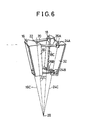
- a quadric crank chain comprises: a first rotary link 20 interconnecting points disposed on a vehicle body 12 and a side door 14 on one side as rotary center shafts 16 and 18 out of four points including two points disposed on the vehicle body 12 and spaced apart from each other and two points disposed on the side door 14; a second rotary link 26 interconnecting points disposed on the vehicle body 12 and the side door 14 on the other side as rotary center shafts 22 and 24; a portion between the two points on the vehicle body 12; and another portion between the two points on the side door 14; the four rotary center shafts 16, 18, 22 and 24 are inclined relative to one another in such a manner that downward extensions of center axes 16C, 18C, 22C and 24C of the four rotary center shafts intersect one another at one point 28.
- the first rotary link 20 is composed of upper and lower links 20A and 20B, which are similar in shape to each other and have their rotary axes on the extensions of the center axes 16C and 18C, respectively.
- the second rotary link 26 is composed of upper and lower links 26A and 26B, which are similar in shape to each other and have their rotary axes on the extensions of the center axes 22C and 24C, respectively.
- first rotary link 20 is composed of a pair of the first upper link 20A and the first lower link 20B and the second rotary link 26 is composed of a pair of the second upper link 26A and the second lower link 26B, the pairs of first and second links rotating in synchronism about the center axes 16C and 18C, and 22C and 24C, respectively.
- the side door hinge mechanism utilizing the quadric crank chain is a small-sized link mechanism interposed between an end panel 14A of the side door 14 and the front pillar 6.
- the rotary center shafts 16A and 22A on the side of the vehicle body 12 are rotatably mounted to an upper bracket 30A on the side of the vehicle body, and the rotary center shafts 18A and 24A on the side of the side door 14 are also rotatably mounted to an upper bracket 32A on the side of the side door.
- the upper bracket 30A on the vehicle body's side and the upper bracket 32A on the door's side compose a quadric crank chain in cooperation with the first upper link 20A and the second upper link 26A.
- the rotary center shafts 16B and 22B of the first lower link 20B and the second lower link 26B on the vehicle body's side are rotatably mounted to a bracket 30B on the vehicle body's side
- the rotary center shafts 18B and 24B of the first lower link 20B and the second lower link 26B on the door's side are also rotatably mounted to a bracket 32B on the door's side.
- the lower bracket 30B on the vehicle body's side and the lower bracket 32B on the door's side compose a quadric crank chain in cooperation with the first lower link 20B and the second lower link 26B.
- the upper bracket 30A and the lower bracket 30B on the vehicle body's side are tightly fastened to the outer surface of the front pillar 6 on the vehicle body's side through bolts 34.
- bracket 32A and the lower bracket 32B on the door's side are tightly fastened to the end panel 14A through bolts 34, similarly.
- the side door 14 is mounted to the vehicle body through the hinge mechanism utilizing the quadric crank chain as described above, so that, when the side door 14 is opened, an opening necessary for the getting on or off the vehicle by the occupant can be obtained with the side door 14 not bulging out of the vehicle body excessively.
- the rotary center shafts 16, 18, 22 and 24 as being the rotary centers in the quadric crank chain are inclined relative to one another in such a manner that the center axes 16C, 18C, 22C and 24C thereof intersect one another at one point 28 located downwardly, so that, when the side door 14 is opened, the top end portion of the side door 14 is largely outwardly inclinedly opened as compared with the bottom end portion thereof as shown in Fig. 5.
- the bottom end of the side door 14 would not interfere with feet of the occupant 10 when he gets on or off the vehicle. Then, the relative angles of inclination at the top end portion of the side door 14 would be larger than those at the bottom end portion of the side door 14, so that the top end portion would be further largely inclined not to interfere with the upper body of the occupant.
- the occupant 10 can get on or off a motor vehicle 11 without inclining his upper body.
- the side door hinge mechanism utilizing the quadric crank chain is made to be as small as to be interposed between the end panel 14A of the side door 14 and the front pillar 6, so that this embodiment is advantageous in that the link mechanism can be rendered compact in size and some parts of the rotary links are not exposed to the compartment as compared with the link mechanism utilizing long rotary links shown in Fig. 1 for example.
- each of the two rotary links is composed of the pair of upper and lower links so as to support a load of the side door 14 and control the rotating paths of the two rotary links.
- the present invention is applied to the side door hinge mechanism as small as to be interposed between the end panel 14A of the side door 14 and the center pillar 6, however, the present invention need not necessarily be limited to this, and the present invention is applicable to the side door hinge mechanism utilizing the long rotary links as shown in Fig. 1 for example.
- one pair of upper and lower quadric crank chains having rotary center shafts on the four center axes 16C, 18C, 22C and 24C are utilized, however, the quadric crank chains utilized need not necessarily be limited to one pair, and a plurality of quadric crank chain more than three or only one quadric crank chain may be utilized.
- the rotary center shafts may be formed long along the center axes 16C, 18C, 22C and 24C.
- a single bracket 30 on the vehicle body's side and a single bracket 32 on the door's side, both of which are formed long along the center axes 16C, 18C, 22C and 24C, a single rotary link 20, and a pair of a second upper link 26A and a second lower link 26B may compose the one quadric crank chain.
- the first rotary link 20 for chiefly supporting the load of the side door 14 is elongated integrally in the vertical direction
- the second rotary link performing the control arm function for controlling the rotating path of the side door 14 is composed of two thin second upper link 26A and second lower link 26B.
- the bracket 30 on the vehicle body's side, the bracket 32 on the door's side and the first rotary link 20, on all of which the loads act on are each formed into a unitary structure of frame elongate in the vertical direction, and the second rotary link performing the control arm function is split into two including the thin second upper link 26A and the thin second lower link 26B, so that the total weight thereof can be reduced.
- bracket 30 on the vehicle body's side and the bracket 32 on the door's side are each formed into a unitary structure of frame elongate in the vertical direction, so that this embodiment is advantageous in that the brackets 30 and 32 can be easily mounted to the vehicle body 12 and the side door 14, respectively.
- the top and the bottom sides of the first rotary link 20 being of a square frame shape are each formed into a U-shape in cross section, and a door check mechanism 36 is assembled between this rotary link 20 and the bracket 30 on the vehicle body's side.
- this door check mechanism 36 is of such an arrangement that a door check body 36A is mounted to the bracket 30 on the vehicle body's side, a bracket 36C to transmit a relative rotary displacement of the side door 14 to a door check arm 36B, which penetrates through and is in sliding contact with this door check body 36A and forms a door checking force, is secured to the rotary link 20, and the forward end of the door check arm 36B is rockingly engaged with the forward end of this bracket 36C through a pin 36D.
- the first rotary link 20 can be further increased in rigidity, the number of parts, weight and number of man-hour for assembling can be reduced by assembling the door check mechanism 36 into a unitary structure, and further, the appearance is improved by disposing the door check mechanism 36 in a position where the door check mechanism cannot be observed from the outside.
Landscapes
- Engineering & Computer Science (AREA)
- Mechanical Engineering (AREA)
- Hinges (AREA)
- Body Structure For Vehicles (AREA)
Applications Claiming Priority (2)
| Application Number | Priority Date | Filing Date | Title |
|---|---|---|---|
| JP157117/83U | 1983-10-11 | ||
| JP1983157117U JPS6064122U (ja) | 1983-10-11 | 1983-10-11 | 自動車のサイドドアヒンジ機構 |
Publications (3)
| Publication Number | Publication Date |
|---|---|
| EP0140245A2 true EP0140245A2 (de) | 1985-05-08 |
| EP0140245A3 EP0140245A3 (en) | 1986-01-02 |
| EP0140245B1 EP0140245B1 (de) | 1989-03-29 |
Family
ID=15642585
Family Applications (1)
| Application Number | Title | Priority Date | Filing Date |
|---|---|---|---|
| EP84112234A Expired EP0140245B1 (de) | 1983-10-11 | 1984-10-11 | Seitentürscharniermechanismus eines Kraftfahrzeugs |
Country Status (4)
| Country | Link |
|---|---|
| US (1) | US4658475A (de) |
| EP (1) | EP0140245B1 (de) |
| JP (1) | JPS6064122U (de) |
| DE (1) | DE3477501D1 (de) |
Cited By (12)
| Publication number | Priority date | Publication date | Assignee | Title |
|---|---|---|---|---|
| EP0180232A3 (en) * | 1984-11-02 | 1986-10-22 | Toyota Jidosha Kabushiki Kaisha | Side door hinge mechanism in motor vehicle |
| EP0180235A3 (en) * | 1984-11-02 | 1986-10-29 | Toyota Jidosha Kabushiki Kaisha | Side door hinge mechanism in motor vehicle |
| EP0180923A3 (en) * | 1984-11-02 | 1986-10-29 | Toyota Jidosha Kabushiki Kaisha | Side door hinge mechanism in motor vehicle |
| US4700983A (en) * | 1984-11-02 | 1987-10-20 | Toyota Jidosha Kabushiki Kaisha | Construction of body of motor vehicle |
| US4700984A (en) * | 1984-11-02 | 1987-10-20 | Toyota Jidosha Kabushiki Kaisha | Construction of body of motor vehicle |
| DE3730520C1 (en) * | 1987-09-11 | 1988-06-23 | Audi Ag | Hinge arrangement of a vehicle door |
| DE4114811A1 (de) * | 1991-05-07 | 1992-11-12 | Waldemar Dipl Ing Fengler | Scharnierarm fuer autotueren |
| DE4339859C1 (de) * | 1993-11-23 | 1995-05-24 | Matthias Herntier | Viergelenkscharnieranordnung für Kraftfahrzeugtüren |
| EP0987392A3 (de) * | 1998-09-14 | 2000-11-15 | Ford Global Technologies, Inc. | Gelenkscharnier für Kraftwagentür |
| EP2239404A3 (de) * | 2009-04-08 | 2014-05-21 | Sugatsune Kogyo CO., LTD. | Scharniervorrichtung und Befestigungselement dafür |
| EP2573303A3 (de) * | 2011-09-22 | 2015-04-15 | Aug. Winkhaus GmbH & Co. KG | Verdeckte Lagerung für einen gegen einen Rahmen schwenkbaren Flügel eines Fensters |
| EP3957812A4 (de) * | 2020-06-16 | 2022-03-23 | Guangdong Xiaopeng Motors Technology Co., Ltd. | Fahrzeugtürscharnier und fahrzeug |
Families Citing this family (12)
| Publication number | Priority date | Publication date | Assignee | Title |
|---|---|---|---|---|
| JPH0426616Y2 (de) * | 1985-06-25 | 1992-06-25 | ||
| GB2298236A (en) * | 1995-02-25 | 1996-08-28 | Rover Group | A door assembly closing device |
| US6149222A (en) * | 1999-07-01 | 2000-11-21 | Daimlerchrysler Corporation | Hinge assembly for a vehicle door |
| US6647592B2 (en) | 2000-12-19 | 2003-11-18 | Daimlerchrysler Corporation | Four bar hinge |
| JP2003154849A (ja) | 2001-11-21 | 2003-05-27 | Fuji Heavy Ind Ltd | せり出しドアヒンジ構造 |
| US6629337B2 (en) * | 2001-11-28 | 2003-10-07 | Edscha Roof Systems Inc. | Double-pivot resistance hinge for motor vehicle door |
| US6845547B2 (en) | 2002-05-20 | 2005-01-25 | Demetrius Calvin Ham | Vertical door conversion kit |
| US7941897B1 (en) | 2002-05-20 | 2011-05-17 | Vertical Doors, Inc. | Vertical door conversion kit |
| DE10341934B4 (de) * | 2003-09-11 | 2005-12-29 | Opel Eisenach Gmbh | Pantograph-Fahrzeugtür, Fahrzeug und Fertigungsverfahren dafür |
| US6808223B1 (en) | 2004-01-14 | 2004-10-26 | Robert Baum | Two way hinge for motor vehicle doors |
| JP6347266B2 (ja) * | 2016-02-19 | 2018-06-27 | マツダ株式会社 | 自動車のドア支持構造 |
| CN114635613B (zh) * | 2022-04-26 | 2024-04-09 | 浙江吉利控股集团有限公司 | 车门铰链装置及汽车 |
Family Cites Families (8)
| Publication number | Priority date | Publication date | Assignee | Title |
|---|---|---|---|---|
| US2956836A (en) * | 1958-09-09 | 1960-10-18 | Rolf E James | Door construction for vehicles and the like |
| US3074755A (en) * | 1960-02-05 | 1963-01-22 | Renault | Door assembly for a vehicle |
| US3095600A (en) * | 1960-03-18 | 1963-07-02 | Gen Motors Corp | Door hinging arrangement for vehicle bodies |
| FR1373795A (fr) * | 1963-08-20 | 1964-10-02 | Cie D Ingenieurs Et Technicien | Véhicule comportant un vantail de porte relié à la coque par leviers |
| US3369833A (en) * | 1966-09-14 | 1968-02-20 | Ford Motor Co | Door check |
| US3594853A (en) * | 1969-07-28 | 1971-07-27 | Atwood Vacuum Machine Co | Automobile door hinging |
| DE2105659A1 (de) * | 1971-02-06 | 1972-08-10 | Volkswagenwerk Ag, 3180 Wolfsburg | Türanordnung fur Fahrzeuge, ins besondere Kraftfahrzeuge |
| US3848293A (en) * | 1973-03-19 | 1974-11-19 | Atwood Vacuum Machine Co | Dual action conical door hinge system |
-
1983
- 1983-10-11 JP JP1983157117U patent/JPS6064122U/ja active Granted
-
1984
- 1984-10-10 US US06/659,308 patent/US4658475A/en not_active Expired - Fee Related
- 1984-10-11 EP EP84112234A patent/EP0140245B1/de not_active Expired
- 1984-10-11 DE DE8484112234T patent/DE3477501D1/de not_active Expired
Cited By (14)
| Publication number | Priority date | Publication date | Assignee | Title |
|---|---|---|---|---|
| EP0180232A3 (en) * | 1984-11-02 | 1986-10-22 | Toyota Jidosha Kabushiki Kaisha | Side door hinge mechanism in motor vehicle |
| EP0180235A3 (en) * | 1984-11-02 | 1986-10-29 | Toyota Jidosha Kabushiki Kaisha | Side door hinge mechanism in motor vehicle |
| EP0180923A3 (en) * | 1984-11-02 | 1986-10-29 | Toyota Jidosha Kabushiki Kaisha | Side door hinge mechanism in motor vehicle |
| US4700983A (en) * | 1984-11-02 | 1987-10-20 | Toyota Jidosha Kabushiki Kaisha | Construction of body of motor vehicle |
| US4700984A (en) * | 1984-11-02 | 1987-10-20 | Toyota Jidosha Kabushiki Kaisha | Construction of body of motor vehicle |
| US4713862A (en) * | 1984-11-02 | 1987-12-22 | Toyota Jidosha Kabushiki Kaisha | Side door hinge mechanism in motor vehicle |
| US4716623A (en) * | 1984-11-02 | 1988-01-05 | Toyota Jidosha Kabushiki Kaisha | Side door hinge mechanism in motor vehicle |
| DE3730520C1 (en) * | 1987-09-11 | 1988-06-23 | Audi Ag | Hinge arrangement of a vehicle door |
| DE4114811A1 (de) * | 1991-05-07 | 1992-11-12 | Waldemar Dipl Ing Fengler | Scharnierarm fuer autotueren |
| DE4339859C1 (de) * | 1993-11-23 | 1995-05-24 | Matthias Herntier | Viergelenkscharnieranordnung für Kraftfahrzeugtüren |
| EP0987392A3 (de) * | 1998-09-14 | 2000-11-15 | Ford Global Technologies, Inc. | Gelenkscharnier für Kraftwagentür |
| EP2239404A3 (de) * | 2009-04-08 | 2014-05-21 | Sugatsune Kogyo CO., LTD. | Scharniervorrichtung und Befestigungselement dafür |
| EP2573303A3 (de) * | 2011-09-22 | 2015-04-15 | Aug. Winkhaus GmbH & Co. KG | Verdeckte Lagerung für einen gegen einen Rahmen schwenkbaren Flügel eines Fensters |
| EP3957812A4 (de) * | 2020-06-16 | 2022-03-23 | Guangdong Xiaopeng Motors Technology Co., Ltd. | Fahrzeugtürscharnier und fahrzeug |
Also Published As
| Publication number | Publication date |
|---|---|
| JPS6064122U (ja) | 1985-05-07 |
| US4658475A (en) | 1987-04-21 |
| DE3477501D1 (en) | 1989-05-03 |
| JPH0132579Y2 (de) | 1989-10-04 |
| EP0140245A3 (en) | 1986-01-02 |
| EP0140245B1 (de) | 1989-03-29 |
Similar Documents
| Publication | Publication Date | Title |
|---|---|---|
| EP0140245A2 (de) | Seitentürscharniermechanismus eines Kraftfahrzeugs | |
| EP0126438B1 (de) | Seitentürscharniermechanismus eines Kraftfahrzeugs | |
| US5491875A (en) | Extended cab pickup truck concealed cargo door hinge | |
| US4637653A (en) | Rear seat cushion in motor vehicle | |
| US4641881A (en) | Side door hinge mechanism in motor vehicle | |
| US5632065A (en) | Extended cab pickup truck concealed cargo door hinge having a spring stop detent | |
| US4382312A (en) | Multiposition hood hinge mechanism | |
| US4800624A (en) | Hinge with elastomerically supported check spring | |
| US5195796A (en) | Deck lid hinge assembly | |
| US5527085A (en) | Sunroof device for vehicle | |
| US5110176A (en) | Automotive side impact protection apparatus | |
| EP0135929B1 (de) | Bedrahtungsaufbau in Kraftfahrzeugseitentüren | |
| US4632447A (en) | Side door hinge mechanism in a motor vehicle | |
| US4559740A (en) | Slider assembly for automotive sliding door | |
| JPS63173722A (ja) | 車両のオ−プンル−フ構造 | |
| EP0125703A2 (de) | Seitentürscharniermechanismus eines Kraftfahrzeugs | |
| US4700984A (en) | Construction of body of motor vehicle | |
| GB1563316A (en) | Hinges | |
| JPH0351614B2 (de) | ||
| EP0180232A2 (de) | Scharniermechanismus für eine Kraftfahrzeugseitentür | |
| GB2175640A (en) | Spring cushioned door check | |
| EP1314597A2 (de) | Scharnieranordnung einer Fahrzeugtür | |
| JP2005153820A (ja) | 自動車のセンタピラー構造 | |
| JPH01186427A (ja) | 自動車のサンルーフ構造 | |
| JPS5927318Y2 (ja) | スキ−キヤリヤ |
Legal Events
| Date | Code | Title | Description |
|---|---|---|---|
| PUAI | Public reference made under article 153(3) epc to a published international application that has entered the european phase |
Free format text: ORIGINAL CODE: 0009012 |
|
| AK | Designated contracting states |
Designated state(s): DE FR GB |
|
| PUAL | Search report despatched |
Free format text: ORIGINAL CODE: 0009013 |
|
| AK | Designated contracting states |
Designated state(s): DE FR GB |
|
| 17P | Request for examination filed |
Effective date: 19860616 |
|
| 17Q | First examination report despatched |
Effective date: 19870715 |
|
| GRAA | (expected) grant |
Free format text: ORIGINAL CODE: 0009210 |
|
| AK | Designated contracting states |
Kind code of ref document: B1 Designated state(s): DE FR GB |
|
| REF | Corresponds to: |
Ref document number: 3477501 Country of ref document: DE Date of ref document: 19890503 |
|
| ET | Fr: translation filed | ||
| PLBE | No opposition filed within time limit |
Free format text: ORIGINAL CODE: 0009261 |
|
| STAA | Information on the status of an ep patent application or granted ep patent |
Free format text: STATUS: NO OPPOSITION FILED WITHIN TIME LIMIT |
|
| 26N | No opposition filed | ||
| REG | Reference to a national code |
Ref country code: GB Ref legal event code: 746 Effective date: 19950807 |
|
| REG | Reference to a national code |
Ref country code: FR Ref legal event code: D6 |
|
| REG | Reference to a national code |
Ref country code: FR Ref legal event code: D6 |
|
| PGFP | Annual fee paid to national office [announced via postgrant information from national office to epo] |
Ref country code: GB Payment date: 19971002 Year of fee payment: 14 |
|
| PGFP | Annual fee paid to national office [announced via postgrant information from national office to epo] |
Ref country code: FR Payment date: 19971009 Year of fee payment: 14 |
|
| PGFP | Annual fee paid to national office [announced via postgrant information from national office to epo] |
Ref country code: DE Payment date: 19971017 Year of fee payment: 14 |
|
| PG25 | Lapsed in a contracting state [announced via postgrant information from national office to epo] |
Ref country code: GB Free format text: LAPSE BECAUSE OF NON-PAYMENT OF DUE FEES Effective date: 19981011 |
|
| GBPC | Gb: european patent ceased through non-payment of renewal fee |
Effective date: 19981011 |
|
| PG25 | Lapsed in a contracting state [announced via postgrant information from national office to epo] |
Ref country code: FR Free format text: LAPSE BECAUSE OF NON-PAYMENT OF DUE FEES Effective date: 19990630 |
|
| REG | Reference to a national code |
Ref country code: FR Ref legal event code: ST |
|
| PG25 | Lapsed in a contracting state [announced via postgrant information from national office to epo] |
Ref country code: DE Free format text: LAPSE BECAUSE OF NON-PAYMENT OF DUE FEES Effective date: 19990803 |