EP0140397A2 - Dispositif de dénudage pour câble coaxial - Google Patents
Dispositif de dénudage pour câble coaxial Download PDFInfo
- Publication number
- EP0140397A2 EP0140397A2 EP84201056A EP84201056A EP0140397A2 EP 0140397 A2 EP0140397 A2 EP 0140397A2 EP 84201056 A EP84201056 A EP 84201056A EP 84201056 A EP84201056 A EP 84201056A EP 0140397 A2 EP0140397 A2 EP 0140397A2
- Authority
- EP
- European Patent Office
- Prior art keywords
- knife
- cable
- guideway
- stripping device
- handle part
- Prior art date
- Legal status (The legal status is an assumption and is not a legal conclusion. Google has not performed a legal analysis and makes no representation as to the accuracy of the status listed.)
- Granted
Links
- 238000009413 insulation Methods 0.000 claims abstract description 19
- 210000000056 organ Anatomy 0.000 claims 1
- 230000004048 modification Effects 0.000 abstract 1
- 238000012986 modification Methods 0.000 abstract 1
- 210000000078 claw Anatomy 0.000 description 6
- 239000000463 material Substances 0.000 description 5
- 230000000694 effects Effects 0.000 description 4
- 238000000034 method Methods 0.000 description 3
- 238000003780 insertion Methods 0.000 description 2
- 230000037431 insertion Effects 0.000 description 2
- 238000003801 milling Methods 0.000 description 2
- 230000000149 penetrating effect Effects 0.000 description 2
- 241001295925 Gegenes Species 0.000 description 1
- 239000000969 carrier Substances 0.000 description 1
- 238000010276 construction Methods 0.000 description 1
- 238000011161 development Methods 0.000 description 1
- 230000018109 developmental process Effects 0.000 description 1
- 239000002655 kraft paper Substances 0.000 description 1
- 239000004033 plastic Substances 0.000 description 1
- 230000001681 protective effect Effects 0.000 description 1
Images


Classifications
-
- H—ELECTRICITY
- H02—GENERATION; CONVERSION OR DISTRIBUTION OF ELECTRIC POWER
- H02G—INSTALLATION OF ELECTRIC CABLES OR LINES, OR OF COMBINED OPTICAL AND ELECTRIC CABLES OR LINES
- H02G1/00—Methods or apparatus specially adapted for installing, maintaining, repairing or dismantling electric cables or lines
- H02G1/12—Methods or apparatus specially adapted for installing, maintaining, repairing or dismantling electric cables or lines for removing insulation or armouring from cables, e.g. from the end thereof
- H02G1/1202—Methods or apparatus specially adapted for installing, maintaining, repairing or dismantling electric cables or lines for removing insulation or armouring from cables, e.g. from the end thereof by cutting and withdrawing insulation
- H02G1/1204—Hand-held tools
- H02G1/1221—Hand-held tools the cutting element rotating about the wire or cable
- H02G1/1224—Hand-held tools the cutting element rotating about the wire or cable making a transverse cut
Definitions
- the invention relates to a stripping device for coaxial cables of the type which has a guideway for an end piece of the cable to be stripped and at least two knives which can be rotated about this end piece and which initially only make a short incision in the cable, which is then made by mutual rotary movement the entire circumference of the cable is expanded.
- a coaxial cable has an inner conductive core, an inner insulation sheath surrounding it, an outer conductive layer (shielding) surrounding it and finally an outer insulation layer surrounding the outer conductive layer.
- an incision closest to the end of the cable is carried out, which extends the deepest and cuts through all the layers mentioned down to the conductive core, and at a certain distance from the first incision, a second incision is made which only cuts through the outer insulation layer, so that after removing the separated insulation part, the outer conductive layer is exposed.
- a further incision can be made between the first and the second incision, which cuts through the outer insulation layer and the outer conductive layer, so that after removal of the separated parts, a section of the inner insulation layer is exposed.
- the present invention sets itself the task of stripping coaxial cables to reduce the braking effect of the cut layers to the extent available in the stripping of ordinary cables, with the two above-mentioned measures according to DE-A-31 40 193 to further increase depending on the choice of the effect can be applied.
- the invention is based on the knowledge that successive engagement of the knives makes it possible for the material displaced at the deepest first incision to move freely over the location of the future second and possibly third incision in the same way as with the stripping of an ordinary cable through a single knife or by means of a single incision.
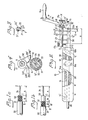
- a coaxial cable 30 is stripped in such a way that at a preselected distance A from the cable end Z in the plane I a first cut to the conductive core 34 of the cable, and at an axial distance B (FIG. 1a) or B + B '(Fig. 1b) of this, in level II, a second incision is made only through the outer insulation layer 31, and optionally (Fig. 1b) in level III, a third incision is made up to the inner insulation layer 33. The separated parts of the insulation are then stripped off the cable. In the rather short section B, when all the knives engage at the same time, material stalls, which in particular brakes the deepest penetrating knife in plane I during the subsequent rotary movement.
- the device 10 has an elongated handle part 11, which is provided with an axial passage opening 11 ′ and is possibly corrugated on the surface, which is not shown.
- a lever 14 protruding somewhat from the surface of the handle part is arranged in an axially extending elongated slot 11 ".
- the end of the lever 14 is articulated and is articulated in the handle part 11 at 14 'at one end, which end is more distant from the guideway member at the opposite end with a braking element in the form of a Rubber block 14a provided.
- the guideway member 12 is in the section protruding from the handle part 11 along a preselected distance up to a certain part of its cross section, e.g. about half, removed, whereby the axial opening 12 'is formed into a trough or support bed forming the actual guideway 12 "for a corresponding end section of the coaxial cable 30 comprising the distances A + B or A + B + B'.
- An adjustable end stop screw 15 enables precise adjustment of the distance A.
- a lever arm 16 projecting essentially at right angles to the guideway 12 "is pivotably mounted in the guideway member 12 at 16 '.
- the lever arm 16 is provided with a rotatably fastened crank handle 16a and forms together with this a crank member.
- an elongated knife carrier 17 which runs at a distance along the guideway 12 "and in the operative position essentially parallel to it, is rotatably limited by means of a bearing pin 17 '.
- the knife carrier 17 can be brought, for example, in a range of ⁇ 25 ° into two different end positions, which are determined by a stop pin 18 which protrudes from the journal 17' and can move in a circular arc-shaped cutout of a preselected dimension - for example 50 ° - in the foot part of the lever arm 16. The two ends of the milling then determine the two end positions of the knife holder.
- Cylindrical knife carriers 17 are individual knives 21 (for the incision at I), 22 (for the incision at II ') and 23 (for the incision at II) inserted and by means of screws such as 21', 22 'in the selected position (lengthwise) secured.
- the arrangement is such that the knives 22 and 23 (the knife 23 is entirely covered by the knife 22 in FIG. 2 and is therefore not visible) assume a different angular position in the cross-sectional direction than the knife 21.
- the knife carrier 17 is either brought into a first end position for the engagement of the knife 21 only, or into a second end position for the engagement of the knife 22 and a possible third knife 23.
- a stopper according to define its working position Fig. 2 are provided, in the example shown, an adjustable stop in the form of a set screw 17b whose end to A nlieqen to the non-ablated portion coming of the guide rail member can.
- the rod-shaped knives 21-23 can advantageously have the known shape of a thin biconvex lens in cross section, as indicated at f. Furthermore, a depression 12a can be arranged in the guideway 12 "at the location of the incision in the plane I or SS. Both the profile shape of the knife and the depression serve to further reduce the knife's friction against the insulation layers, whereby the recess 12a is provided for receiving a local bulge in the cut insulation layer.
- the handle part 11 is firmly gripped by the user with one hand, the lever 14 being pressed down and the rubber block 14a being pressed onto the inserted cable 30. Then the button 17a is actuated such that the knife carrier 17 is pivoted in such a way that the knife 21 penetrates the cable 30. This movement removes the knives 22 and 23 from the cable even further.
- the previously limited incision of the knife 21 is made over the entire circumference of the cable 30 expanded, the insulation layers are in no way hindered to move freely in the axial direction of the cable (to the left in Fig. 2).
- the guideway 12 "thus rotates around the stationary cable 30, which is pressed against it by the engaging knife.
- the guideway can expediently be provided with a friction-reducing inner clothing, for example made of plastic known for this purpose, be provided (see Fig. 11).
- the knife carrier 17 is then brought into the second end position, where the knives 22 and 23 make incisions, the knife 21 having been removed from the cable. During at least one new full revolution, the incisions of these knives are also extended over the entire circumference of the cable 30. Then the knife carrier 17 is brought into the rest position by pivoting the lever arm 16 in the direction of the arrow P and / or is turned into the non-engaged position by pressing the button 17a and the cable 30 is pulled out of the device (to the left in FIG. 2). The knife carrier can possibly remain in the working and engagement position and then when the cable is pulled out the separated parts are held and stripped by the engaging knives 22, 23.
- FIG. 4 shows an alternative embodiment of the knives, where the knives 210 and 220 have circular cutting edges 210 'and 220' which, like the knives 21, 22, engage the cable 30 from opposite sides and their end tips 210 ", 220 "When approaching in the engagement position, circular paths M and N describe the same type as the tips of the knives 21 and 22 in FIG. 3.
- the tilting movement of the knife holder 17 about the pivot point 16 'in FIG. 1 can also be replaced by a straight-line, parallel movement of the knife carrier 17.
- Such a movement can, however, also be completely omitted, in that only the middle non-engagement position (for example according to FIG. 4) of the knife carrier is used to insert the cable into the device.
- a device 10 'of this type is shown in FIG. 5.
- the knife carrier 17 is rotatably supported on both sides in bearing blocks 160, 162 to a predetermined limited extent, and runs parallel 2 with the guideway 12 ".
- the handle 16a is arranged on an arm 161 which, like the button 17a according to FIG. 2, is non-rotatably connected to the knife holder 17.
- the knife holder 17 When the handle 16a is actuated for rotation, for example clockwise, the knife holder 17 is initially in its end position provided for the full engagement of the knife 21 up to the stop of the bolt 18 (FIG. 2) is brought to one end of the circular-arc-shaped milling, and then the whole part 12 is set in rotation. After at least one full turn, the handle 16a becomes Rotation is actuated in the opposite direction and the process is repeated for the knives 22 and 23 (after the pin 18 has reached the opposite end of the circular-arc-shaped cutout) In at least one of the bearing blocks 160, 162 there is also the aforementioned snap-in arrangement with the spring-loaded ball 18 'intended to determine the mean non-engagement position.
- the device 10 has an elongated handle part 111, at one end of which a through opening 111 'is provided transversely to the longitudinal direction of the handle part. Following the through opening 111', a guide track member 112 is rotatably mounted in the handle part 111, which protrudes on one side at right angles from the handle part 111. A guide track 112 'is arranged in the guide track member 112 in a manner similar to the guide track member 12.
- a bow-shaped knife carrier 117 can be pivoted by means of a pin 116' which has a protruding lever arm 116 which is provided with a crank handle 116a, a U-shaped spring 116b whose bent legs extend on both sides of the knife carrier 117, while the web 116b '(FIG. 12) crosses the end of the guideway 112' the knife holder in the pivoted rest position shown.
- the knife carrier 117 has a web Part 117e projecting legs 117c, 117d, which enclose a central space in which a knife cartridge 120 is housed.
- the knife cartridge 120 essentially has the shape of a thick plane-parallel plate with front and rear surfaces 120 ', 120 "and is provided with a large number of straight-line incisions such as 120a which extend from the front surface 120' to approximately half the thickness of the cartridge 120 and with Knives such as 121, 122, 123.
- the incisions 120a are closed by a cover plate 120b which is screwed onto the front surface 120 ', so that the height of the knives 121-123 in the slots 120a of the cartridge can be set precisely according to FIG At least along some of these slots there are threaded bores into which small set screws 120d (Fig. 8) can be screwed which act on the inner ends of the knives.
- a cover plate 120b which is screwed onto the front surface 120 ', so that the height of the knives 121-123 in the slots 120a of the cartridge can be set precisely according to FIG At least along some of these slots there are threaded bores into which small set screws 120d (Fig. 8) can be screwed which act on the inner ends of the knives.
- small set screws 120d Fig. 8
- a keyhole-shaped notch 118 is provided on the inner surfaces of the two legs 117c, 117d, each having a wider circular part 118a which has a diameter D and a subsequent narrower straight part 118b which has a width B.
- the straight part 118b extends at right angles to the direction of the legs 117c, 117d and the lever arm 116.
- Short bearing journals 124, 125 protrude from both side surfaces 120s of the cartridge 120 and are delimited by two flat and two cylindrical surfaces and whose cross-sectional shape is best shown in FIG. 9 can be seen.
- the flat surfaces run parallel to the front and rear surfaces 120 ', 120 "of the cartridge 120 at a mutual distance b which corresponds to the width B of the straight part 118b of the notch 118.
- the cylindrical surfaces extend at a mutual distance between the flat surfaces d the the Diameter D of the circular part 118a corresponds to the notch 118.
- the distance e between the longitudinal axis x of the pins 124, 125 and the upper edge 120k "of the rear surface 120" corresponds exactly to the distance F between the center C of the circular part 118a of the notch 118 and the lower boundary surface 117'e of the web part 117e.
- the distance h between the longitudinal axis x and the upper edge 120k 'of the front surface 120' is shorter than the distance e, at least to the extent that it lies on an arc of a circle struck from x with a radius x-120k "
- the upper surface 120c of the cartridge 120 can be cranked, beveled or, as illustrated, be designed kinked, that is to say from a first planar part 120c 'which runs at right angles to the rear surface 120 "and adjoins this, and a beveled part thereto , flat or cranked second part 120c "adjoining the front surface 120 '.
- the cartridge 120 is then brought into its working position with a certain snap effect, the size of the snap effect being determined by the width of the first part and by the flexibility of the construction elements involved .
- the cartridge 120 with its trunnions 124, 125 is inserted into the notches 118 in such a position that the flat surfaces of the trunnions slide along the walls of the notch parts 118b, and the front surface 120 'of the cartridge 120 to the web part 117e of the knife carrier 117 is agile.
- the cartridge 120 is erected by turning 90 ° until the upper edge 120k "abuts the web part 117e. The above-mentioned distances of the edges 120k 'and 120k" thus allow a rotation of 90 °, but not further.
- the locking arrangement in the device 10 consists of an automatic clamping chuck 300 with three elongated clamping jaws 301, 302, 303.
- a pot-shaped actuating element 310 is rotatably supported with its bottom wall 311 turned outwards. It has a grooved outer side surface 312 with a diameter K, which is somewhat larger than the width k of the handle member 111, so that parts 312 ', 312 "of the side surface 312 protrude somewhat laterally from the handle part 111 and can be easily actuated by fingers of the hand by which the handle part 111 has been gripped .
- the pins 313-315 have a narrower shaft part which is not visible because it is located below the bottom wall 311, and a wider head part located above the bottom wall 311.
- the clamping jaws 301, 302, 303 are freely rotatably supported at one end by the respective shaft part .
- the bottom wall 311 has a circular opening 111'a of the through opening 111 'in the middle and three circular-arc-shaped slots 323, 324, 325 running parallel to the side surface 312 on the periphery, and three radial openings between these slots and the opening 111'a rectilinear slots 333, 334, 335.
- the slots 323-325 have a width which corresponds to the diameter of the shaft parts of the pins 313-315 and is smaller than the diameter of their head parts. The actuator 310 is thus held by the pins 313-315 in the handle part 111 with the possibility of rotation the length of the slots 323-325.
- a protective wall 111a protruding from the handle part 111 protects the finger (s) acting on the actuating element 312 from sliding into the area of the knife carrier 117.
- the user grasps the crank handle 116a and, when the rather weak spring 116 is overcome, pivots the knife carrier 117 in the direction of the arrow T until the knife 121 closest to the leg 117d touches the inserted cable. From the explanations for FIGS. 1a and 1b it is clear that this is always the knife which has to make the deepest incision and therefore protrudes the most from the knife holder. Now the rotation of the entire knife carrier 117 including the guideway part 112 around the cable is started, and at the same time the pivoting in the direction of the arrow T continues. As a result, the knife 121 gradually penetrates deeper and deeper into the cable, and after a while the knife 122 and any other knife closer to the handle part 111, such as 123, touches the cable and begins to penetrate the cable.
- the delay in the engagement of the individual knives is partly caused by the fact that each knife other than the one closest to the leg 117d protrudes less from the knife holder, but mainly by the fact that each such knife is at a greater distance from the pivot pin 116 ' located.
- the pivoting movement in the direction of arrow T is completed when the lower end 117c 'of the leg 117c strikes a collar 112a on the guideway member 112. Then, or at most a few turns later, the rotary movement is also interrupted and the stripping process is finished. From the course described it can be seen that, analogously to the device 10 according to FIG. 2, the insulation parts were able to move freely in the longitudinal direction of the cable for a time after the first intervention of the knife 121.
- the device 10 "has the advantage that the user with the hand operating the crank handle 116 feels very precisely what resistance each individual cable provides, and thus how quickly or slowly on the one hand the pivoting in the direction of the arrow T, and on the other hand the rotation about it Cables can progress around.
- a carriage 114 is arranged on the outside of the guideway member 112 and, according to FIG. 12, has bent longitudinal edges 114a on the outer end of which a projecting engagement claw 114a ', 114a "is provided.
- the carriage 114 is slidable with the longitudinal edges 114a on the longitudinal edges of the guideway member 112 one of the engaging claws 114a ", one of the end edges, 113a", of the inserted inserts, for example 113a, comprises.
- the other engaging claw 114a ' engages in an elongated track 113 which is arranged at a distance from and parallel to the other longitudinal edge 113a' 11 in the inclined position shown in FIG. 11, since both engagement claws 114a ′, 114a ′′ are of the same height.
- the inserts are somewhat shorter than the guideway, as can be seen in FIG. 12, and have an opening 113 "in the bottom area into which a short pin 112b arranged in the bottom area of the guideway member 112 engages.
- the carriage 114 is shorter than the guideway member 112 (see 6) and the individual inserts 113a-113c are inserted and removed in such a way that the slide 114 is displaced up to the end of the guide track member 112 remote from the handle part 111, ie to the right in FIG. 12 (arrow Q)
- the engagement claw 114a 'the track 113' and the engagement claw 114a "the longitudinal edge 113a" so that the insert 113a can be lifted off the pin 112b.
- the insertion is carried out in the wrong order.
Landscapes
- Removal Of Insulation Or Armoring From Wires Or Cables (AREA)
Applications Claiming Priority (2)
| Application Number | Priority Date | Filing Date | Title |
|---|---|---|---|
| SE8304627 | 1983-08-26 | ||
| SE8304627A SE8304627D0 (sv) | 1983-08-26 | 1983-08-26 | Abisoliergeret fur koaxialkabel |
Publications (3)
| Publication Number | Publication Date |
|---|---|
| EP0140397A2 true EP0140397A2 (fr) | 1985-05-08 |
| EP0140397A3 EP0140397A3 (en) | 1986-12-10 |
| EP0140397B1 EP0140397B1 (fr) | 1990-05-09 |
Family
ID=20352309
Family Applications (1)
| Application Number | Title | Priority Date | Filing Date |
|---|---|---|---|
| EP84201056A Expired - Lifetime EP0140397B1 (fr) | 1983-08-26 | 1984-07-16 | Dispositif de dénudage pour câble coaxial |
Country Status (4)
| Country | Link |
|---|---|
| US (1) | US4616533A (fr) |
| EP (1) | EP0140397B1 (fr) |
| DE (1) | DE3482226D1 (fr) |
| SE (1) | SE8304627D0 (fr) |
Cited By (3)
| Publication number | Priority date | Publication date | Assignee | Title |
|---|---|---|---|---|
| EP0227466A3 (fr) * | 1985-12-23 | 1988-07-20 | Warren & Brown & Staff Pty. Ltd. | Outils pour dénuder des fils |
| US8296956B2 (en) | 2007-08-16 | 2012-10-30 | Wezag Gmbh Werkzeugfabrik | Pliers |
| WO2016180630A1 (fr) * | 2015-05-11 | 2016-11-17 | Huber+Suhner Ag | Outil à dénuder |
Families Citing this family (4)
| Publication number | Priority date | Publication date | Assignee | Title |
|---|---|---|---|---|
| AU604664B2 (en) * | 1985-12-23 | 1991-01-03 | Warren & Brown & Staff Pty. Ltd. | Wire stripper |
| US6643448B1 (en) * | 2001-04-13 | 2003-11-04 | Wavesplitter Technologies, Inc. | Optical fiber stripping tool |
| US7316058B2 (en) * | 2005-08-15 | 2008-01-08 | Beam-Chi Jee | Coaxial cable stripper |
| KR102521045B1 (ko) * | 2016-11-23 | 2023-04-11 | 쿠퍼스탠다드오토모티브앤인더스트리얼 주식회사 | 편조기 |
Citations (1)
| Publication number | Priority date | Publication date | Assignee | Title |
|---|---|---|---|---|
| DE3140193A1 (de) | 1980-08-29 | 1983-04-28 | C.A. Weidmüller GmbH & Co, 4930 Detmold | Werkzeug zum abisolieren von kabeln |
Family Cites Families (4)
| Publication number | Priority date | Publication date | Assignee | Title |
|---|---|---|---|---|
| US2455591A (en) * | 1944-12-04 | 1948-12-07 | William S Lindsay | Insulation cutting tool |
| US3161088A (en) * | 1962-12-04 | 1964-12-15 | Harold J Tolman | Stripper for coaxial cables |
| US3688404A (en) * | 1970-12-29 | 1972-09-05 | Albert G Muller | Insulation cable cutter |
| CH609176A5 (fr) * | 1976-04-26 | 1979-02-15 | Loepfe K Automation Ag |
-
1983
- 1983-08-26 SE SE8304627A patent/SE8304627D0/xx unknown
-
1984
- 1984-07-16 DE DE8484201056T patent/DE3482226D1/de not_active Expired - Fee Related
- 1984-07-16 EP EP84201056A patent/EP0140397B1/fr not_active Expired - Lifetime
- 1984-08-01 US US06/636,541 patent/US4616533A/en not_active Expired - Fee Related
Patent Citations (1)
| Publication number | Priority date | Publication date | Assignee | Title |
|---|---|---|---|---|
| DE3140193A1 (de) | 1980-08-29 | 1983-04-28 | C.A. Weidmüller GmbH & Co, 4930 Detmold | Werkzeug zum abisolieren von kabeln |
Cited By (4)
| Publication number | Priority date | Publication date | Assignee | Title |
|---|---|---|---|---|
| EP0227466A3 (fr) * | 1985-12-23 | 1988-07-20 | Warren & Brown & Staff Pty. Ltd. | Outils pour dénuder des fils |
| US8296956B2 (en) | 2007-08-16 | 2012-10-30 | Wezag Gmbh Werkzeugfabrik | Pliers |
| WO2016180630A1 (fr) * | 2015-05-11 | 2016-11-17 | Huber+Suhner Ag | Outil à dénuder |
| US11133654B2 (en) | 2015-05-11 | 2021-09-28 | Huber+Suhner Ag | Stripping tool |
Also Published As
| Publication number | Publication date |
|---|---|
| EP0140397A3 (en) | 1986-12-10 |
| US4616533A (en) | 1986-10-14 |
| DE3482226D1 (de) | 1990-06-13 |
| EP0140397B1 (fr) | 1990-05-09 |
| SE8304627D0 (sv) | 1983-08-26 |
Similar Documents
| Publication | Publication Date | Title |
|---|---|---|
| DE3140193A1 (de) | Werkzeug zum abisolieren von kabeln | |
| DE102017110516B4 (de) | Einrichtung zum Abtrennen von Papierabschnitten von auf einer Papierrolle aufgewickelten Papierbahn sowie Messer zum Abtrennen der Papierabschnitte | |
| DE2810165A1 (de) | Verfahren und vorrichtung zum perforieren von schlaeuchen sowie verfahren zur herstellung einer leitspindel zur verwendung in einer vorrichtung zum perforieren von schlaeuchen | |
| EP0073534B1 (fr) | Outil pour dénuder des fils électriques | |
| DE10242881A1 (de) | Multifunktionale Beschneidmaschine | |
| DE10047545B4 (de) | Schneid- und Transportwalze mit integrierter Schneidvorrichtung mit schwenkbaren Schneidflächen und Verfahren zum Schneiden von Materialbahnen mithilfe einer solchen Walze | |
| EP0140397A2 (fr) | Dispositif de dénudage pour câble coaxial | |
| CH642553A5 (de) | Skibremse. | |
| EP3325336A1 (fr) | Dispositif d'actionnement d'un mécanisme de changement de vitesse | |
| EP0206376B1 (fr) | Dispositif pour dénuder | |
| DE2715445B2 (de) | Vorrichtung zum Entfernen von Schmutzteilchen von einem Formzylinder einer Rotations-Offsetdruckmaschine | |
| DE2848445C2 (de) | Gerät zum Abisolieren von elektrischen Leitern | |
| DE2711557C2 (de) | Längenanschlag für Scheren | |
| DE102021131694B3 (de) | Kabelentmantelungswerkzeug | |
| EP0211182A2 (fr) | Scie de jardinier | |
| EP0173858A2 (fr) | Verrouillage contre une connexion répétée pour interrupteur de démarrage pour machines à combustion interne | |
| DE19523566C1 (de) | Handbetätigter Ratschenschneider, insbesondere Kabelschneider | |
| DE630494C (de) | Sicherheitsrasierapparat | |
| DE19511372A1 (de) | Kombinierte Abisolier-/Crimpvorrichtung | |
| EP0089074A2 (fr) | Disposition pour séparer des conducteurs individuels l'un de l'autre dans un câble-ruban plat | |
| EP0930682B1 (fr) | Procédé et appareil pour enlever la gaine extérieure de l'extrémité d'un câble | |
| LU100917B1 (de) | Werkzeug | |
| DE69607498T2 (de) | Türgriff eines Kraftfahrzeugs zur schnellen Montage durch ein System mit drehbaren Stiften | |
| DE3013608A1 (de) | Vorrichtung zum zurichten der kopfenden von koaxialkabeln | |
| DE2225069C3 (de) | Elektrischer Bleistiftspitzer |
Legal Events
| Date | Code | Title | Description |
|---|---|---|---|
| PUAI | Public reference made under article 153(3) epc to a published international application that has entered the european phase |
Free format text: ORIGINAL CODE: 0009012 |
|
| AK | Designated contracting states |
Designated state(s): CH DE FR GB IT LI SE |
|
| PUAL | Search report despatched |
Free format text: ORIGINAL CODE: 0009013 |
|
| AK | Designated contracting states |
Kind code of ref document: A3 Designated state(s): CH DE FR GB IT LI SE |
|
| 17P | Request for examination filed |
Effective date: 19861124 |
|
| 17Q | First examination report despatched |
Effective date: 19880408 |
|
| ITF | It: translation for a ep patent filed | ||
| GRAA | (expected) grant |
Free format text: ORIGINAL CODE: 0009210 |
|
| AK | Designated contracting states |
Kind code of ref document: B1 Designated state(s): CH DE FR GB IT LI SE |
|
| GBT | Gb: translation of ep patent filed (gb section 77(6)(a)/1977) | ||
| REF | Corresponds to: |
Ref document number: 3482226 Country of ref document: DE Date of ref document: 19900613 |
|
| ET | Fr: translation filed | ||
| ITTA | It: last paid annual fee | ||
| PGFP | Annual fee paid to national office [announced via postgrant information from national office to epo] |
Ref country code: FR Payment date: 19910111 Year of fee payment: 8 |
|
| PLBE | No opposition filed within time limit |
Free format text: ORIGINAL CODE: 0009261 |
|
| STAA | Information on the status of an ep patent application or granted ep patent |
Free format text: STATUS: NO OPPOSITION FILED WITHIN TIME LIMIT |
|
| 26N | No opposition filed | ||
| PGFP | Annual fee paid to national office [announced via postgrant information from national office to epo] |
Ref country code: CH Payment date: 19910514 Year of fee payment: 8 |
|
| PGFP | Annual fee paid to national office [announced via postgrant information from national office to epo] |
Ref country code: DE Payment date: 19910702 Year of fee payment: 8 |
|
| PGFP | Annual fee paid to national office [announced via postgrant information from national office to epo] |
Ref country code: SE Payment date: 19910719 Year of fee payment: 8 |
|
| PGFP | Annual fee paid to national office [announced via postgrant information from national office to epo] |
Ref country code: GB Payment date: 19920706 Year of fee payment: 9 |
|
| PG25 | Lapsed in a contracting state [announced via postgrant information from national office to epo] |
Ref country code: SE Effective date: 19920717 |
|
| PG25 | Lapsed in a contracting state [announced via postgrant information from national office to epo] |
Ref country code: LI Effective date: 19920731 Ref country code: CH Effective date: 19920731 |
|
| PG25 | Lapsed in a contracting state [announced via postgrant information from national office to epo] |
Ref country code: FR Effective date: 19930331 |
|
| REG | Reference to a national code |
Ref country code: CH Ref legal event code: PL |
|
| PG25 | Lapsed in a contracting state [announced via postgrant information from national office to epo] |
Ref country code: DE Effective date: 19930401 |
|
| REG | Reference to a national code |
Ref country code: FR Ref legal event code: ST |
|
| PG25 | Lapsed in a contracting state [announced via postgrant information from national office to epo] |
Ref country code: GB Effective date: 19930716 |
|
| GBPC | Gb: european patent ceased through non-payment of renewal fee |
Effective date: 19930716 |
|
| EUG | Se: european patent has lapsed |
Ref document number: 84201056.3 Effective date: 19930204 |