EP0140433B2 - Désileuse à couteau ainsi que machine agricole comportant un organe de prélèvement pourvu d'une désileuse similaire - Google Patents
Désileuse à couteau ainsi que machine agricole comportant un organe de prélèvement pourvu d'une désileuse similaire Download PDFInfo
- Publication number
- EP0140433B2 EP0140433B2 EP84201442A EP84201442A EP0140433B2 EP 0140433 B2 EP0140433 B2 EP 0140433B2 EP 84201442 A EP84201442 A EP 84201442A EP 84201442 A EP84201442 A EP 84201442A EP 0140433 B2 EP0140433 B2 EP 0140433B2
- Authority
- EP
- European Patent Office
- Prior art keywords
- teeth
- cutter
- silage
- support member
- knife
- Prior art date
- Legal status (The legal status is an assumption and is not a legal conclusion. Google has not performed a legal analysis and makes no representation as to the accuracy of the status listed.)
- Expired - Lifetime
Links
Images




Classifications
-
- A—HUMAN NECESSITIES
- A01—AGRICULTURE; FORESTRY; ANIMAL HUSBANDRY; HUNTING; TRAPPING; FISHING
- A01F—PROCESSING OF HARVESTED PRODUCE; HAY OR STRAW PRESSES; DEVICES FOR STORING AGRICULTURAL OR HORTICULTURAL PRODUCE
- A01F25/00—Storing agricultural or horticultural produce; Hanging-up harvested fruit
- A01F25/16—Arrangements in forage silos
- A01F25/20—Unloading arrangements
- A01F25/2027—Unloading arrangements for trench silos
- A01F25/2036—Cutting or handling arrangements for silage blocks
Definitions
- the invention relates to a silage cutter according to the preamble of claim 1, and to an agricultural device provided with a receiving member having such a silage cutter.
- Such a silage cutter is described in DE-A-2 918 650.
- the teeth of the support member protrude at most immediately downwards with the knife teeth, these support organ teeth forming the counter-cutting edges to the knife teeth.
- such a silage cutter does not have a satisfactory cutting effect, which is caused by the fact that the layer of silage in which the teeth of the knife organ protrude is not cut well by the knife organ, particularly in the case of silage with a fiber structure .
- EP-A 0 090 906 which belongs to the state of the art within the meaning of Art. 54 (3) (4) EPU, relates to a silage cutter in which the support member acts as a second knife member, the two knife members each relative to the other can be moved vertically up and down. The cutting effect therefore takes place in the vertical direction.
- the invention is based on the object of creating a silage cutter which can cut through the crop faster and better than the known silage cutter.
- the invention further relates to an agricultural device provided with a receiving member, which is characterized in that this receiving member has a silage cutter according to the invention.
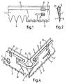
- FIG. 1 shows a part of a first embodiment of a cutting device of the silage cutter according to the invention in a front view.
- FIG. 2 is a cross section of the cutting device of FIG. 1.
- FIG. 3 is a perspective view of a first embodiment of a silage cutter according to the invention with the cutting device according to FIG. 1.
- FIG. 4 shows in perspective a corner area of the cutting device according to FIG. 3 on a larger scale.
- Fig. 5 shows part of a second embodiment of a cutting device according to the invention in front view.
- FIG. 6 is a cross section of the cutting device of FIG. 5.
- FIG. 7 shows in perspective a corner area of the cutting device according to FIG. 5 on a larger scale.
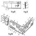
- Fig. 8 shows part of a third embodiment of a cutting device according to the invention in front view.
- FIG. 9 is a cross section of the cutting device of FIG. 8.
- FIG. 10 shows in perspective a corner area of the cutting device according to FIG. 8 on a larger scale.
- FIG. 11 shows in perspective a somewhat modified version of the silage cutter according to FIG. 3, which is designed with a dropping element.
- FIGS. 12-15 schematically show different stages when cutting out a block of silage with the silage cutter according to FIG. 11.
- FIGS. 12 and 14 are schematic plan views on a larger scale for FIGS. 12 and 14, respectively.
- FIG. 18 is a schematic partial side view of the upstanding part of the frame of a silage cutter, as well as a support member guided therein (the knife elements of which are omitted) in an embodiment in which this support member can experience a slight pivoting.
- FIG. 19 is a cross section through the plane XIX-XIX in FIG. 18.
- FIG. 1 shows an exemplary embodiment of a cutting device of the silage cutter according to the invention for cutting cattle feed or the like.
- This cutting device comprises a support element 1 which can be moved up and down at least approximately vertically and which supports a knife element 3 designed with teeth 2.
- This knife member 3 is at least approximately horizontally oscillating back and forth relative to the support member 1.
- the support member 1 has lower retaining teeth 4, which project lower than the knife teeth 2 down.
- the knife member 3 is also preferably arranged on the outside of the support member 1.
- the distance between the tips of subsequent knife teeth 2 is preferred smaller than the distance between the tips of the following holding teeth 4 of the support member 1, while the height of the knife teeth 2 is smaller than the height of the holding teeth 4 of the support member 1.
- the flanks of the knife teeth 2 form a smaller angle with the connecting line of their tooth tips than the angle enclosed by the flanks of the retaining teeth 4 of the support member 1 with the connecting line of their tooth tips.
- flanks of the knife teeth 2 are straight and form an angle with the connecting line of the tooth tips which is less than 50 ° and preferably less than or equal to 30 °.
- flanks of the knife teeth 2 can also be curved inwards.
- the retaining teeth 4 of the support member 1 run downwards obliquely in the direction of the knife member 3, while the knife teeth 2 run downwards obliquely in the direction of the support member 1 (FIG. 2).
- the support member 1 is also designed with an upper support edge 5 for the knife member 3, along which the upper edge of the knife member 3 is adjustable to and fro.
- This support edge 5 carries downwardly projecting sealing lips 6, the knife element 3 being enclosed between these sealing lips 6 and the supporting element 1 so that it can move back and forth.
- the support member 1 and the knife member 3 are held against each other by a guide member, which in the embodiment according to FIGS. 1 and 2 consists of one or more slots 7 in the knife member 3, which are passed through by pins protruding from the support member 1. Upwards from the knife organ 3, the pins carry a sealing plate 7 ', a nut or the like.
- the knife element may carry 3 pins which pass through the slots in the support element 1 in a suitable manner.
- the stroke of the reciprocating oscillating movement of the knife element 3 is generally greater than the distance between the tips of subsequent knife teeth of the knife element 3.
- the support member 1 and the knife member 3 are plate-shaped.
- the knife member 3 can also consist, for example, of a chain with teeth or the like.
- a plate-shaped Messerogan 3 is preferred because it is easier to lock against an upward adjustment relative to the support member 1.
- the support member 1 can be designed in the form of a profile or box instead of a plate.
- the support member 1 cooperates with only one knife member 3, the support member 1 can also in the manner shown in Figs. 5 - 10 support another toothed knife member 3 ', the parallel to the knife member 3 shown and that is preferably adjustable at least approximately horizontally back and forth relative to the support member 1, the teeth of the knife members 3, 3 'being reciprocally movable back and forth. 5 - 10 only one further knife member 3 'is shown, of course, several further knife members 3' can be used.
- the support member 1 is designed without lower retaining teeth, but as an alternative, retaining teeth 4 can also be used in these embodiments.
- the flanks of the knife teeth of the (each) further knife member 3 include a smaller angle with the connecting line of their tooth tips than the angle enclosed by the flanks of the holding teeth with the connecting line of their tooth tips.
- the pins carry a sealing plate 7', a nut or the like.
- flanks of the knife teeth of the (each) knife member 3, 3 ' are straight in the embodiment according to FIGS. 5-7 and include an angle with the connecting line of the tooth tips, which is less than 50 ° and preferably less than or equal to 30 ° .
- the embodiment of the cutting device according to FIGS. 8-10 differs only from the embodiment according to FIGS. 5-7, in that the flanks of the knife teeth of the (each) further knife member 3 'are bent inwards.
- the downward or upward adjustment of the support member 1 can take place continuously, but as an alternative it is also possible that the downward adjustment of the support member 1 is intermittent and the upward adjustment of the support member 1 is continuous.
- the support member 1 can be L-shaped and cooperate with an L-shaped knife member 3 made of flexible material.
- the L-shaped support element 1 interacts with at least one knife set consisting of two knife elements 3 which together form an L-shaped knife member 3.
- the support member 1 is U-shaped (see FIGS. 3 and 11).
- the three knife elements 3, which together form a U-shaped knife element, are coupled to one another and act together with drive elements, which are described in more detail below, and which engage the free ends of the two lateral knife elements 3.
- the adjacent ends of subsequent knife elements 3 are coupled to one another by an at least approximately horizontal chain 8, band or the like, the ends of which are fastened to the relevant knife elements 3 and via a support element 1 in the respective corner supported idler 9 is guided with at least approximately vertical longitudinal axis.
- a conical protective piece 10 runs above and below the guide roller 9.
- the middle leg 1 'of the U-shaped support member 1 runs further upward than the two side legs 1 ⁇ to prevent that loosened crop would fall down over this side.
- the silage cutter 11 shown in FIGS. 3 and 11, on which the cutting device described above is arranged, has a frame 12 which is provided with attachment points 13 for coupling the silage cutter 11 to the lifting device of a tractor.
- the frame 12 comprises an upright frame part 14, behind which a horizontal cross bar 15 extends, to which a plurality of parallel, at least approximately horizontal support tines 16 are fastened.
- the crossbar 15 is rigidly connected to the upright frame part 14 in the embodiment of FIG. 3.
- the upward and downward adjustment of the U-shaped support member 1 is accomplished with the aid of adjustment members carried by the frame 12. 3 consist of an upright cylinder-piston unit 19 supported by the frame 12, the piston rod 19 'of which carries a disk block 20.
- the support member 1 is adjustable up and down.
- the three knife elements 3, supported by the support member 1, which are connected by the chains 8, bands or the like, which are guided in the corners of the support member 1, which are removed from the upright frame part 14, via the guide rollers 9 (FIG. 4), 3 can be moved back and forth relative to the support member 1 by means of cylinder-piston units 26 which are supported on the support member 1 and which act on the free ends of the two lateral knife elements 3.
- This cylinder-piston units 26, which in this Embodiment are double-acting, are operated via a hydraulic changeover valve and check valves (not shown) such that the piston rods 26 'of the two cylinder-piston units 26 are always adjusted in the opposite direction, whereby the knife elements 3 receive a reciprocating movement.
- the two double-acting cylinder-piston units 26 are hydraulically coupled to the upright cylinder-piston unit 19, which supplies the upward and downward movement of the support member 1.
- the support member 1 is adjusted step by step, each step coinciding with a reciprocating movement of the knife elements 3.
- a silage cutter 11 is shown, in which the upward and downward adjustment of the U-shaped support member 1 is accomplished in a different manner, with the aid of chains 23 or the like which engage the ends of the side legs 1 ⁇ of the support member 1 are guided via upper drive wheels and lower deflection wheels.
- the lower deflection wheels are mounted in the upright frame part 14, while the upper drive wheels are fastened on a drive shaft 24, which is mounted in the upright frame part 14 and which can be driven with a reversible direction of rotation via a drive wheel 25 by means of a chain by means of a hydraulic motor or the like (not shown) is.
- the uppermost and lowermost position of the support member 1 is determined by reversing members (not shown), which can supply the reversal of the direction of rotation of the hydraulic motor.
- the drive means for the reciprocating movement of the knife elements 3 again consist of cylinder-piston units 26 which engage the free ends of the two lateral knife members 3.
- the silage cutter 11 according to FIG. 11 is designed with an upper throwing member 27, with which a block of silage, after it has been transferred to a cattle shed by means of the silage cutter 11 coupled behind a tractor, can be distributed regularly.
- the upper ejector member 27, which is supported by the upright frame part 14, comprises a discharge conveyor 28, which consists of chains (not shown) which can be driven by a drive and which engage at the ends of writing strips 30 provided with pins 29 or the like, which act in the lower part Run of the discharge conveyor 28 can act on the silage.
- the upright frame part 14 comprises, instead of U-profiles 18, I-profiles 31, while the crossbeam 15 is not rigidly connected to the upstanding frame part 14, but carries guide rollers 32, guide blocks or the like, which engage with the inside thereof I profiles 31 are.
- I-profiles 31 are on the outside, in a manner corresponding to the U-profiles 18 in Fig. 3, with the, supported by the free ends of the U-shaped support member 1 guide rollers 17, guide blocks or the like in engagement.
- the up and down adjustment of the crossbar 15 can, for example, in a manner corresponding to the up and down adjustment of the support member 1 of the cutting device, by means of the crossbar 15 coupled, guided by drive wheels, endless chains or the like (not shown) or one in the vertical direction working, carried by the frame 12, cylinder-piston unit (not shown).
- a central, at least approximately horizontal knife 33 with lower cutting teeth interacts with the discharge conveyor 28 and lies at least approximately in the central plane of the transverse beam 15.
- This knife 33 can be driven back and forth in its longitudinal direction by a drive element, such as the cylinder-piston unit 34 shown in FIG. 11, which is supported by the frame 12.
- central knife 33 it is also possible to use a plurality of drivable, parallel, at least approximately horizontal knives with lower cutting teeth that run at a distance from one another.
- the cutting device is in its highest position, just below the discharge conveyor 28 and surrounds the knife 33 and the upper part of the block of silage just below it.
- the upper part of the silage material block resting on these carrying tines 16 is brought into engagement with the knife 33 (the knives) which cut through the upper layer of the silage material ( cut) before the pins 29 of the machining elements 30 of the discharge conveyor 28 come into engagement with the latter.
- the use of the knife 33 (the knife) is particularly important if the silage has a fibrous structure, since the long fibers are cut and divided by the knife 33 (the knife) before being thrown off by the discharge conveyor 28, as a result of which a uniform one Removal of the silage is very required.
- the discharge conveyor 28 is adjustable to and fro in the longitudinal direction of the crossbar 15, the knife 33 (the knives) maintaining its position relative to the frame 12.
- This adjustment option is important because, in a so-called driving silo, usually two side walls run on both sides of the silage bulk. If the silage cutter 11 along one wall has to cut the first block of silage, the removal conveyor 28, which is always longer than the width of the block of silage, otherwise the crop cannot be poured over the side edge of the block of silage, is brought into its position away from this wall, while cutting the last silage block along the opposite wall of the discharge conveyor 28 is adjusted to its other end position.
- the crossbeam 15 can be locked in its lower position relative to the frame 12, which is important when the carrying tines 16 are introduced into the silage.
- a stop for which the crossbar 15 is used in the silage cutter 11 according to FIG. 11, limits the depth of penetration into the silage of the supporting tines 16 fastened to the crossbar 15 such that the upright frame part 14 after the Carrying tines 16 are guided into the silage, still at a distance, for example, about 5 cm, from the silage.
- the corners of the U-shaped support member 1 facing away from the upright frame part 14 are somewhat larger than 90 °, and preferably approximately 94 ° (FIGS. 16 and 17).
- the support member 1 with the knife elements 3 has started the cutting action.
- the carrying tines 16 and / or the frame 12 of the silage cutter 11 are dimensioned such that, under the influence of the cutting force, a deformation of the carrying tines 16 and / or the frame 12 occurs.
- the frame 12 is raised somewhat from the ground under the influence of the cutting force exerted, the carrying tines 16 and possibly the frame 12 being bent.
- Fig. 14 the cutting device has reached its lower position, in which the holding teeth 4 of the support member 1 have come into contact with the ground, while the tips of the knife teeth 2 are a short distance above the ground.
- the cutting device will be adjusted to its uppermost end position and the silage cutter 11 will be raised (Fig. 15), after which it can be driven by the tractor to the cattle shed.
- the block of silage is gradually moved upwards by the upward adjustment of the crossbeam 15 and the carrying tines 16 (FIG. 15) and brought into engagement with the knife 33 (the knives) and also with the discharge conveyor 28 in order to be regularly discarded .
- the scantling movement can also be accomplished with the help of a special scantling organ.
- silage cutter 11 an embodiment of a silage cutter 11 is shown, in which the ends of the two side legs 1 ⁇ of the support member 1 each have an upward extension 36, in which two guide rollers 37 or the like are supported one above the other, in the associated profile 38 of the upright frame part 14 are guided appropriately.
- the lower of the two guide rollers 37 engages on both sides by means of an eccentric 39 on the relevant side leg 1 ⁇ of the support member 1.
- Each eccentric 39 is connected to an actuating member 40 with which the eccentric 39 can be rotated between two positions shown in broken lines and in dashed lines in FIG. 18, the position of the eccentric 39 shown in solid lines and the support member 1 being the working position , in which the knife elements, not shown in FIGS. 18 and 19, can carry out their cutting action, while in the position shown in dashed lines the support member 1 is pivoted somewhat upwards about the axis of the upper guide rollers 37, whereby the support member 1 is practically free from the cut-out Silage block is coming. In this way, after the cutting of a silage block upward adjustment of the support member 1 with the knife elements 3 attached to it can be accomplished particularly easily.
- the adjustment of the control element 40 can take place automatically, simultaneously with the reversal of the adjustment direction of the support element 1.
Landscapes
- Life Sciences & Earth Sciences (AREA)
- Environmental Sciences (AREA)
- Threshing Machine Elements (AREA)
Claims (14)
Priority Applications (2)
| Application Number | Priority Date | Filing Date | Title |
|---|---|---|---|
| AT84201442T ATE40258T1 (de) | 1982-09-03 | 1982-09-03 | Silagegutschneider, sowie landwirtschaftliches geraet versehen mit einem aufnahmeorgan, das einen dergleichen silagegutschneider aufweist. |
| EP84201442A EP0140433B2 (fr) | 1982-09-03 | 1982-09-03 | Désileuse à couteau ainsi que machine agricole comportant un organe de prélèvement pourvu d'une désileuse similaire |
Applications Claiming Priority (1)
| Application Number | Priority Date | Filing Date | Title |
|---|---|---|---|
| EP84201442A EP0140433B2 (fr) | 1982-09-03 | 1982-09-03 | Désileuse à couteau ainsi que machine agricole comportant un organe de prélèvement pourvu d'une désileuse similaire |
Related Parent Applications (1)
| Application Number | Title | Priority Date | Filing Date |
|---|---|---|---|
| EP82810368.9 Division | 1982-09-03 |
Publications (4)
| Publication Number | Publication Date |
|---|---|
| EP0140433A2 EP0140433A2 (fr) | 1985-05-08 |
| EP0140433A3 EP0140433A3 (en) | 1985-06-19 |
| EP0140433B1 EP0140433B1 (fr) | 1989-01-25 |
| EP0140433B2 true EP0140433B2 (fr) | 1992-02-05 |
Family
ID=8192485
Family Applications (1)
| Application Number | Title | Priority Date | Filing Date |
|---|---|---|---|
| EP84201442A Expired - Lifetime EP0140433B2 (fr) | 1982-09-03 | 1982-09-03 | Désileuse à couteau ainsi que machine agricole comportant un organe de prélèvement pourvu d'une désileuse similaire |
Country Status (2)
| Country | Link |
|---|---|
| EP (1) | EP0140433B2 (fr) |
| AT (1) | ATE40258T1 (fr) |
Families Citing this family (6)
| Publication number | Priority date | Publication date | Assignee | Title |
|---|---|---|---|---|
| FR2591420B1 (fr) * | 1985-12-18 | 1989-03-03 | Audureau Sa | Desileuse a griffe |
| DE3601112A1 (de) * | 1986-01-16 | 1987-07-23 | Lengerich Maschf | Vorrichtung zum entnehmen von silagegut |
| NL8602592A (nl) * | 1986-10-16 | 1988-05-16 | Lely Nv C Van Der | Inrichting voor het snijden van voer, zoals kuilvoer. |
| DE3636775A1 (de) * | 1986-10-29 | 1988-05-05 | Strautmann & Soehne | Flachsilo-entnahmegeraet |
| DE3811924A1 (de) * | 1988-04-09 | 1989-10-19 | Hans Von Der Heide | Silagegutschneidegeraet mit u-foermigem tragerahmen |
| US5297021A (en) * | 1992-11-16 | 1994-03-22 | Koerlin James M | Zero shear recliner/tilt wheelchair seat |
Citations (1)
| Publication number | Priority date | Publication date | Assignee | Title |
|---|---|---|---|---|
| DE3023986A1 (de) † | 1980-06-26 | 1982-01-14 | Heinrich 3013 Barsinghausen Bleinroth | Geraet zur entnahme von silage |
Family Cites Families (5)
| Publication number | Priority date | Publication date | Assignee | Title |
|---|---|---|---|---|
| US3741051A (en) * | 1971-05-26 | 1973-06-26 | Hesston Corp | Stack feeding method and apparatus |
| DE2138186C3 (de) * | 1971-07-30 | 1974-09-12 | Fa. Heinrich Schaeffer, 4782 Erwitte | Gerät zum mechanischen Ausschneiden und zum Transport von Silage |
| FR2323608A1 (fr) * | 1975-09-12 | 1977-04-08 | Sudrie Jean | Appareil de desilage pour silo-tranchee ou silo-couloir |
| DE2752234A1 (de) * | 1977-11-23 | 1979-06-07 | Bosch Gmbh Robert | Heckenschere |
| EP0090906B1 (fr) * | 1982-04-01 | 1986-07-30 | Mullos B.V. Trioliet | Dispositif de coupe pour un produit ensilé |
-
1982
- 1982-09-03 AT AT84201442T patent/ATE40258T1/de not_active IP Right Cessation
- 1982-09-03 EP EP84201442A patent/EP0140433B2/fr not_active Expired - Lifetime
Patent Citations (1)
| Publication number | Priority date | Publication date | Assignee | Title |
|---|---|---|---|---|
| DE3023986A1 (de) † | 1980-06-26 | 1982-01-14 | Heinrich 3013 Barsinghausen Bleinroth | Geraet zur entnahme von silage |
Also Published As
| Publication number | Publication date |
|---|---|
| EP0140433B1 (fr) | 1989-01-25 |
| ATE40258T1 (de) | 1989-02-15 |
| EP0140433A3 (en) | 1985-06-19 |
| EP0140433A2 (fr) | 1985-05-08 |
Similar Documents
| Publication | Publication Date | Title |
|---|---|---|
| EP0102437B2 (fr) | Découpeur d'ensilage et outil agricole classique muni d'un tel découpeur d'ensilage | |
| DE2138186C3 (de) | Gerät zum mechanischen Ausschneiden und zum Transport von Silage | |
| DE1507384A1 (de) | Dreschmaschine | |
| DE8807242U1 (de) | Mähvorrichtung, verstopfungshemmend, dynamisch ausgeglichen | |
| EP0140433B1 (fr) | Désileuse à couteau ainsi que machine agricole comportant un organe de prélèvement pourvu d'une désileuse similaire | |
| EP0923853B1 (fr) | Appareil et méthode de désagrégation d'un bloc de matériau comprimé spécialement terre de plantation | |
| DE2205172C2 (de) | Entnahmegerät für Fahrsilos | |
| DE2522970A1 (de) | Vorrichtung zum zufuehren von abgelaengten draehten zu einer arbeitsmaschine, insbesondere einer gitterschweissmaschine | |
| DE69701385T2 (de) | Schneid-, hebe- und trennungsvorrichtung | |
| DE2902521C3 (de) | Vorrichtung zur Entnahme von Futter aus einem Flachsilo | |
| DE7920491U1 (de) | Vorrichtung zum entnehmen von gaerfutter aus fahrsilos | |
| DE2724322C2 (de) | Vorrichtung zum Zuschneiden und Transportieren eines Silageblockes | |
| DE8428246U1 (de) | Schneidvorrichtung zum schneiden von viehfutter oder dergleichen gewaechs | |
| DE3024057C2 (de) | Silofräse | |
| DE3143982C2 (fr) | ||
| DE715927C (de) | Vorrichtung zum maschinellen Aufschneiden flottierender Kettfaeden | |
| DE3232284A1 (de) | Geraet zum entnehmen von futterportionen aus flach- oder fahrsilos | |
| DE139275C (fr) | ||
| DE3111868A1 (de) | Vorrichtung zum ausschneiden und zum transport von silage | |
| DE2037293A1 (de) | Vorrichtung zum Beschneiden von Wein stocken | |
| DE3932020A1 (de) | Vorrichtung zum schneiden von hecken | |
| DE2918650A1 (de) | Geraet zum entnehmen von futterportionen aus silos | |
| DE2712204A1 (de) | Geraet zum entnehmen von futterportionen aus silos | |
| DE3683C (de) | Verbesserungen in der Mälzerei des Getreides | |
| EP0499772A1 (fr) | Dispositif de transport et de déchargement pour un bloc de fourrage |
Legal Events
| Date | Code | Title | Description |
|---|---|---|---|
| PUAI | Public reference made under article 153(3) epc to a published international application that has entered the european phase |
Free format text: ORIGINAL CODE: 0009012 |
|
| PUAL | Search report despatched |
Free format text: ORIGINAL CODE: 0009013 |
|
| AC | Divisional application: reference to earlier application |
Ref document number: 102437 Country of ref document: EP |
|
| AK | Designated contracting states |
Designated state(s): AT BE CH DE FR GB IT LI LU NL SE |
|
| AK | Designated contracting states |
Designated state(s): AT BE CH DE FR GB IT LI LU NL SE |
|
| 17P | Request for examination filed |
Effective date: 19850503 |
|
| RAP1 | Party data changed (applicant data changed or rights of an application transferred) |
Owner name: TRIOLIET MULLOS B.V. |
|
| 17Q | First examination report despatched |
Effective date: 19860530 |
|
| R17C | First examination report despatched (corrected) |
Effective date: 19870202 |
|
| ITF | It: translation for a ep patent filed | ||
| GRAA | (expected) grant |
Free format text: ORIGINAL CODE: 0009210 |
|
| AC | Divisional application: reference to earlier application |
Ref document number: 102437 Country of ref document: EP |
|
| AK | Designated contracting states |
Kind code of ref document: B1 Designated state(s): AT BE CH DE FR GB IT LI LU NL SE |
|
| REF | Corresponds to: |
Ref document number: 40258 Country of ref document: AT Date of ref document: 19890215 Kind code of ref document: T |
|
| REF | Corresponds to: |
Ref document number: 3279384 Country of ref document: DE Date of ref document: 19890302 |
|
| GBT | Gb: translation of ep patent filed (gb section 77(6)(a)/1977) | ||
| ET | Fr: translation filed | ||
| PLBI | Opposition filed |
Free format text: ORIGINAL CODE: 0009260 |
|
| 26 | Opposition filed |
Opponent name: EMIL HEGEMANN Effective date: 19891014 |
|
| NLR1 | Nl: opposition has been filed with the epo |
Opponent name: EMIL HEGEMANN |
|
| PGFP | Annual fee paid to national office [announced via postgrant information from national office to epo] |
Ref country code: BE Payment date: 19910916 Year of fee payment: 10 |
|
| PGFP | Annual fee paid to national office [announced via postgrant information from national office to epo] |
Ref country code: LU Payment date: 19911024 Year of fee payment: 10 |
|
| PUAH | Patent maintained in amended form |
Free format text: ORIGINAL CODE: 0009272 |
|
| STAA | Information on the status of an ep patent application or granted ep patent |
Free format text: STATUS: PATENT MAINTAINED AS AMENDED |
|
| 27A | Patent maintained in amended form |
Effective date: 19920205 |
|
| AK | Designated contracting states |
Kind code of ref document: B2 Designated state(s): AT BE CH DE FR GB IT LI LU NL SE |
|
| REG | Reference to a national code |
Ref country code: CH Ref legal event code: AEN |
|
| EPTA | Lu: last paid annual fee | ||
| NLR2 | Nl: decision of opposition | ||
| GBTA | Gb: translation of amended ep patent filed (gb section 77(6)(b)/1977) | ||
| NLR3 | Nl: receipt of modified translations in the netherlands language after an opposition procedure | ||
| ET3 | Fr: translation filed ** decision concerning opposition | ||
| PGFP | Annual fee paid to national office [announced via postgrant information from national office to epo] |
Ref country code: CH Payment date: 19920731 Year of fee payment: 11 |
|
| PGFP | Annual fee paid to national office [announced via postgrant information from national office to epo] |
Ref country code: GB Payment date: 19920824 Year of fee payment: 11 |
|
| PG25 | Lapsed in a contracting state [announced via postgrant information from national office to epo] |
Ref country code: LU Free format text: LAPSE BECAUSE OF NON-PAYMENT OF DUE FEES Effective date: 19920903 |
|
| PGFP | Annual fee paid to national office [announced via postgrant information from national office to epo] |
Ref country code: SE Payment date: 19920918 Year of fee payment: 11 |
|
| PG25 | Lapsed in a contracting state [announced via postgrant information from national office to epo] |
Ref country code: BE Effective date: 19920930 |
|
| BERE | Be: lapsed |
Owner name: TRIOLIET MULLOS B.V. Effective date: 19920930 |
|
| PG25 | Lapsed in a contracting state [announced via postgrant information from national office to epo] |
Ref country code: GB Effective date: 19930903 |
|
| PG25 | Lapsed in a contracting state [announced via postgrant information from national office to epo] |
Ref country code: SE Effective date: 19930904 |
|
| PG25 | Lapsed in a contracting state [announced via postgrant information from national office to epo] |
Ref country code: LI Effective date: 19930930 Ref country code: CH Effective date: 19930930 |
|
| GBPC | Gb: european patent ceased through non-payment of renewal fee |
Effective date: 19930903 |
|
| REG | Reference to a national code |
Ref country code: CH Ref legal event code: PL |
|
| EUG | Se: european patent has lapsed |
Ref document number: 84201442.5 Effective date: 19940410 |
|
| PGFP | Annual fee paid to national office [announced via postgrant information from national office to epo] |
Ref country code: FR Payment date: 19980909 Year of fee payment: 17 |
|
| PGFP | Annual fee paid to national office [announced via postgrant information from national office to epo] |
Ref country code: AT Payment date: 19980914 Year of fee payment: 17 |
|
| PG25 | Lapsed in a contracting state [announced via postgrant information from national office to epo] |
Ref country code: AT Free format text: LAPSE BECAUSE OF NON-PAYMENT OF DUE FEES Effective date: 19990903 |
|
| PG25 | Lapsed in a contracting state [announced via postgrant information from national office to epo] |
Ref country code: FR Free format text: LAPSE BECAUSE OF NON-PAYMENT OF DUE FEES Effective date: 20000531 |
|
| REG | Reference to a national code |
Ref country code: FR Ref legal event code: ST |
|
| PGFP | Annual fee paid to national office [announced via postgrant information from national office to epo] |
Ref country code: NL Payment date: 20011129 Year of fee payment: 20 |
|
| PGFP | Annual fee paid to national office [announced via postgrant information from national office to epo] |
Ref country code: DE Payment date: 20011203 Year of fee payment: 20 |
|
| PG25 | Lapsed in a contracting state [announced via postgrant information from national office to epo] |
Ref country code: NL Free format text: LAPSE BECAUSE OF EXPIRATION OF PROTECTION Effective date: 20020903 |
|
| NLV7 | Nl: ceased due to reaching the maximum lifetime of a patent |
Effective date: 20020903 |