EP0140446A2 - Fermeture-distributeur - Google Patents
Fermeture-distributeur Download PDFInfo
- Publication number
- EP0140446A2 EP0140446A2 EP84201526A EP84201526A EP0140446A2 EP 0140446 A2 EP0140446 A2 EP 0140446A2 EP 84201526 A EP84201526 A EP 84201526A EP 84201526 A EP84201526 A EP 84201526A EP 0140446 A2 EP0140446 A2 EP 0140446A2
- Authority
- EP
- European Patent Office
- Prior art keywords
- closure
- inflexed
- slit
- check valve
- self
- Prior art date
- Legal status (The legal status is an assumption and is not a legal conclusion. Google has not performed a legal analysis and makes no representation as to the accuracy of the status listed.)
- Withdrawn
Links
Images
Classifications
-
- B—PERFORMING OPERATIONS; TRANSPORTING
- B65—CONVEYING; PACKING; STORING; HANDLING THIN OR FILAMENTARY MATERIAL
- B65D—CONTAINERS FOR STORAGE OR TRANSPORT OF ARTICLES OR MATERIALS, e.g. BAGS, BARRELS, BOTTLES, BOXES, CANS, CARTONS, CRATES, DRUMS, JARS, TANKS, HOPPERS, FORWARDING CONTAINERS; ACCESSORIES, CLOSURES, OR FITTINGS THEREFOR; PACKAGING ELEMENTS; PACKAGES
- B65D47/00—Closures with filling and discharging, or with discharging, devices
- B65D47/04—Closures with discharging devices other than pumps
- B65D47/20—Closures with discharging devices other than pumps comprising hand-operated members for controlling discharge
- B65D47/2018—Closures with discharging devices other than pumps comprising hand-operated members for controlling discharge comprising a valve or like element which is opened or closed by deformation of the container or closure
- B65D47/2031—Closures with discharging devices other than pumps comprising hand-operated members for controlling discharge comprising a valve or like element which is opened or closed by deformation of the container or closure the element being formed by a slit, narrow opening or constrictable spout, the size of the outlet passage being able to be varied by increasing or decreasing the pressure
Definitions
- This invention relates to a dispensing closure for use in a fluid product dispenser, and, more particularly, to an externally mounted, self-sealing, pressure actuated check valve dispensing closure for fluid product dispensers.
- Discharge closures and dispensing closures having a dispensing orifice which automatically increases in diameter in response to fluid pressure within are not new to the art.
- U.S. Patent 591,067 which issued to David Wallace on October 5, 1897, discloses an automatic siphoning device comprising a flexible sleeve having a discharge end which concentrically converges and contracts to a small orifice.
- the circumference of the small orifice is formed or molded into a number of flute- shaped corrugations B which extend from the contracted orifice end C axially toward the connecting end D over a length of several inches.
- Such corrugations are described as being preferably of equal breadth and depth and arranged in close successive order around the circumference of the device.
- liquid can normally. pass through the small orifice in the contracted end C of the device, and as the pressure of the liquid increases the corrugated folds of the device begin to expand, thus increasing the size of the orifice.
- the expansion of the orifice will continue under continual increasing liquid-pressure until the orifice area is nearly as large as the area of the cylindrical portion A of the siphoning device.
- the corrugated folds return to their original shape as the liquid pressure is decreased.
- a dispensing closure for collapsible type fluid containers is disclosed in U.S. Patent 2,937,795, which issued to Pasquale Ciliberti on May 24, 1960.
- a dispensing closure device 10 is described as including a conical closure member 11 provided with a plurality of intersecting slits 14 which serve to divide the tip of closure member 11 into a plurality of individual flexible quadrants 15.
- Closure member 11 is hollow, and increased internal pressure of the contents 16 therewithin acts to force the quadrants 15 apart thereby permitting the dispensing of the contents therethrough. Upon release of the internal pressure, the quadrants 15 return to their normally closed position.
- the closure wall 21 may exist either as a laterally extending wall, as shown in Figure 7, or as the end wall of a plurality of pairs of walls helicoidally arranged and coming together at their ends to form radiating slits from a generally central point.
- the neck 20 of dispensing device 12 is to be formed of a plastic material having a stiffness and elasticity proportioned to the viscosity of the paste to be dispensed such that internal pressure within the paste will press the internal walls of the paths to each of the slits (slits 22-25) thereby moving the walls defining the path apart and opening the slits. Upon release of such internal pressure, the resulting force on the sides of the paths to the slits will also be released and the slits will helically return to a closed position.
- a unitized three-leaflet heart valve is taught in U.S. Patent 4,222,126, which issued to John Boretos et al. on September 16, 1980.
- the tri-leaflet heart valve 10 comprises a rigid frame 12 covered with a one-piece membrane 14 forming the three leaflets 14a, 14b and 14c which are bonded to the frame 12 to form an integral unit.
- Membrane 14 is also provided with a thickened lip 18 which forms the free ends of the leaflets 14a, 14b and 14c.
- the thickened nature of lip 18 serves to increase its tear strength and increases the reliability and longevity of valve 10.
- a transitional area 20 in the upper regions of frame 12 serves to distribute fluxural stress at the points at which the membrane 14 is attached to frame 12. Additionally, the radiating lines 22 consisting of heavier areas provide strength without bulk to the valve.
- blood under pressure forces the valve leaflets into an open positiorr. Upon release of such pressure, the valve resiliently returns to Its normally closed state.
- an externally mounted integral, self-sealing check valve dispensing closure for use in a fluid product dispenser which is formed of a resilient plastic or elastomer having a durometer in the range of between approximately 10 Shore A and 95 Shore A (46 Shore D) and having a wall thickness in the range of from about .25 mm to about 1.3 mm (.01 to .05 inches).
- the closure includes a substantially tubular open inlet end and a normally closed outlet end. The outlet end converges from a substantially tubular shape along at least one inflexed non-planar surface which mates along its distal edge with at least one other, oppositely disposed surface of the closure to form a non-linear discharge slit.
- the inflexed non-planar surface converges toward the normally closed discharge slit in such a manner as to form an acute angle at the slit with any line drawn through the slit parallel to the central axis of the nozzle and mates with the other oppositely disposed surface along substantially flat lands of contact along the length of the slit.
- the inflexed non-planar surface is adapted to resiliently deflect outwardly in response to the application of product pressure from within the closure, thereby opening the closure and allowing product to be dispensed therethrough. Upon release of product pressure therewithin, the inflexed non-planar surface resiliently returns to its closed condition thereby sealing the closure.
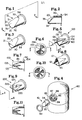
- Figures 1 through 4 illustrate the setf-sealing check valve dispensing closure 10 which is preferably molded of silicone rubber (e.g. Silastic( TM ) MDX 4-4526 available from Dow-Corning of Midland, Michigan), although a wide variety of materials (e.g., any resilient plastic or elastomer such as silicone rubber or plasticized polyvinyl chloride) and molding procedures can be used.
- silicone rubber e.g. Silastic( TM ) MDX 4-4526 available from Dow-Corning of Midland, Michigan
- any resilient plastic or elastomer such as silicone rubber or plasticized polyvinyl chloride
- the check valve dispensing nozzle 10 must be resiliently flexible enough to readily open in response to increased pressure within a product dispenser, while at the same time exhibiting sufficient rigidity to maintain its general conformation and to return to its dosed condition upon release of product pressure therewithin. It has been found that resilient plastics or elastomers having a durometer in the range of between approximately 10 Shore A and 95 Shore A (46 Shore D) and having a wall thickness in the range of from about .25 mm to 1.3 mm (.01 to .05 inches) provide such desired characteristics. Accordingly, it can be seen that stiffer materials would necessarily have to be thinner to maintain the required resilient flexibility.
- Self-sealing dispensing closure 10 includes a substantially tubular open inlet end 30 and a normally closed outlet end 31.
- An attachment flange 34 is integrally formed about the periphery of open end 30 and extends outwardly in a plane substantially perpendicular to the central axis of closure 10.
- Outlet end 31 converges from a substantially tubular shape toward its closed end along the inflexed non-planar surface 20 to the normally closed non-linear discharge slit 33.
- the distal edge of inflexed non-planar surface 20 mates with the lower tubular- shaped surface 32 along the curved discharge slit 33.
- the lands of contact 35 (seen best in Figure 2) between the inflexed non-planar surface 20 and the oppositely disposed tubular shaped surface 32 are substantially flat and have a width (measured along the central longitudinal axis of closure 10) of preferably approximately .66 mm (.026 inches) in a closure having an inside diameter of its tubular inlet end 30 of approximately 8 mm (.315 inches).
- lnflexed non-planar surface 20 is formed in an inclined relationship relative to the central longitudinal axis of closure 10 and forms an acute angle at slit 33 with any line drawn through slit 33 parallel to the central axis of the closure. As will be seen in greater detail below, this angular relationship importantly augments the ability of closure 10 to perform as a self-sealing check valve by permitting the nozzle to maintain an effective seal.
- Closure 10 is preferably formed of silicone with a durometer of 35 Shore A with a wall thickness of approximately .76 mm (.03 inches) in its cylindrical open end 30 and approximately .51 mm (0.02 inches) in its inflexed non-planar surface 20.
- the distal edges of inflexed surface 20 and the lower tubular shaped surface 32 are attenuated in the immediate vicinity of slit 33 to permit their surfaces to mate along the substantially flat lands of contact 35, as shown in Figure 2.
- closure 10 results in a wall thickness at the distal edge of inflexed surface 20 of approximately .076 mm (.003 inches) when inflexed surface 20 forms a forty five degree angle at slit 33, as described above, and the lands of contact 35 have a width of approximately .66 mm (.026 inches), as described in greater detail below. It has been found that such flat lands of contact at the discharge slit insure a reliable seal of closure 10 along discharge slit 33 and provide the closure the ability to effectively seal a container at an air/product interface (i.e., closure 10 can effectively seal a container and act as a check-valve to isolate the contained product from ambient air subsequent a dispensing operation).
- Closure check valve 10 is to be mounted externally onto a dispensing package, such as, for example, in place of the dispensing outlets and check-valves of the dispensers disclosed in U.S. Patent 3,088,636 which issued to Spatz on May 7, 1963, or U.S. 4,154,371 which issued to Kolarzinski et al. on May 15, 1979, or U.S. 4,301,948 which issued to Czech et al. on November 24, 1981.
- Such external mounting situates the closure of a dispensing system at the outermost point, thereby reducing messiness by providing positive product cut-off after dispensing operations.
- closures desirable alternatives for other closure devices in applications not requiring a check valve (e.g., collapsible tubes containing products such as pastes, gels, creams and the like).
- An example of a means for attaching closure 10 to a dispensing package is illustrated in Figure 4.
- the cylindrical open end 30 of closure 10 is telescoped over the protuberance 88 formed on dispensing package 80 and circumscribing the outlet passageway 83, and is positively held in place by a retaining ring 90 which slides over the exterior of closure 10 and is snapped passed the inwardly extending retention rib 87 formed on the inner surfaces of the retaining wall 86.
- Retaining ring 90 is preferably made of polypropylene.
- closure 10 to the package is not critical, however, and can be accomplished by a variety of ways known'or conceivable by those skilled in the art, such as by adhesives, heat sealing, or other mechanical arrangements.
- closure 10 is shown in Figure 3 in a partially opened condition.
- the pressure required to initiate dispensing through closure 10 can be predetermined and controlled by varying the material characteristics of closure 10 (e.g., a closure formed of material of higher durometer or flexural modulus would require more pressure to deflect outwardly the inflexed surface 20), and by varying the wall thicknesses and/or the diameter thereof while taking into consideration the viscosity of the product to be dispensed (product having lower viscosity will generally require less pressure to dispense).
- a closure formed of material of higher durometer or flexural modulus would require more pressure to deflect outwardly the inflexed surface 20
- wall thicknesses and/or the diameter thereof while taking into consideration the viscosity of the product to be dispensed (product having lower viscosity will generally require less pressure to dispense).
- a closure formed of material of higher durometer or flexural modulus would require more pressure to deflect outwardly the inflexed surface 20
- wall thicknesses and/or the diameter thereof while taking into consideration the visco
- the dispensing pressure at which there is appreciable product flow is approximately 0.10 kg/cm 2 [1.5 lbs. per square inch (psig)].
- a dispensing pressure of approximately 0.14 kg/cm [2.0 Ibs. per square inch (psig)] would be required.
- closures of the present invention exhibit low back pressure to product dispensing not only because of the resiliently flexible material properties, but also because of the non-planar overall conformation of their discharge slits. As can be seen in Figure 3, deflection of non-planar surface 20 does not require flexing of the end points 21 of discharge slit 33. Likewise, a corresponding relationship can be seen by the non-flexure of end points 121 in Figure 8.
- Closures with linear discharge slits e.g., common duckbill closures
- closure 10 will resiliently tend to close due to the elastic memory of its material. Further reduction of pressure within the dispenser below atmospheric pressure will cause such ambient pressure to act upon the exterior surfaces of closure 10, further closing and sealing the slit 33 in a substantially fluid-tight condition.
- the closure 10 can therefore be successfully utilized as a check valve against the flow of fluids (including air) into a dispenser.
- the flat lands of contact 35 have a width of approximately .66 mm (.026 inches), measured in a direction parallel to the central axis of closure 10. It has been found that although the land width can be as small as approximately .2 mm (.008 inches), a better seal against the inflow of fluids through the slit 33 is achieved by lands of contact 35 being wider than such minimum value. Because the closures of the present invention must exhibit a certain degree of softness so as to be flexible as well as resilient, it is conceivable that a negative pressure within the sealed closure could cause the outlet end 31 to collapse inwardly. It has been observed that wider lands of contact augment the closure's resistance to such back pressure, and will better resist the tendency to collapse under negative pressure.
- the width of lands 35 can be widely varied without significant deterioration of the check valve capabilities of closure 10, the preferred range for the width of lands 35 is between approximately 0.5 and 1.0 mm (.02-.04 inches). It has also been found that to insure the capability of slit 33 to fully close, it is preferred that closure 10 be molded without slit 33, and thereafter cutting slit 33 while closure 10 is in an unstressed condition. Cutting slit 33 in this manner forms the flat -lands of contact 35 which permit slit 33 to exactly close whenever closure 10 is unstressed--making closure 10 a very effective self sealing outlet.
- Figures 5 through 8 illustrate an alternate embodiment of the subject check valve dispensing closure of the current invention.
- Figures 5 through 8 illustrate check valve dispensing closure 100 comprising a generally cylindrical open inlet end 130 and an outlet end 131 which terminates at a normally closed non-linear discharge slit 133.
- An attachment flange 134 corresponding to the attachment flange 34 of the first described closure 10. is integrally formed about the bottom peripheral edge of open end 130.
- Outlet end 131 converges toward its closed end along three inflexed non-planar surfaces 120 which are equally spaced about the central axis of closure 100.
- Inflexed non-planar surfaces 120 correspond to the inflexed surface 20 of closure 10, however, the surfaces 120 each include a centrally located groove 122 which causes each inflexed non-planar surface 120 to assume a more angular overall conformation (i.e., a multiplanar surface).
- the more angular shape of the inflexed surfaces 120 facilitates the close mating of the distal edges of surfaces 120 along a normally closed discharge slit 133. It can be seen that while portions of surface 120 can be planar, the overall surface 120 must be non-planar to maintain the advantages of the closures described herein. Likewise portions of discharge slit 133 can be linear; however, overall, the discharge slit must be non-linear in conformation.
- closure 100 is preferably formed with wall thicknesses of approximately .76 mm (.03 inches) in its cylindrical open end 130 and .5 mm (.02 inches) in its inflexed non-planar surfaces 120.
- the distal ends of the non-planar surfaces 120 can be attenuated in the immediate vicinity of the slit 133 to facilitate the establishment of the flat lands of contact 135, as can be seen best in Figure 7. It is also apparent in Figure 7 that the distal ends of the lands of contact 135 are squared off as opposed to being tapered to a point.
- each of the inflexed non-planar surfaces 120 of the closure 100 converge toward the closed end, and each forms an acute angle at the slit 133 with any line drawn through slit 133 parallel to the central axis of closure 100.
- inflexed non-planar surfaces 120 tend to maintain their normally closed position more effectively, especially when subjected to a vacuum pressure from within.
- Closure 100 is to be mounted externally on a dispenser in the same manner as described above with regard to closure 10.
- the operation of closure 100 also corresponds to the operation of closure 10, as described above.
- Increased product pressure within nozzle 100 exerts outward forces normal to the inner surfaces of inflexed non-planar surfaces 120.
- the product pressure reaches a certain required dispensing pressure, such pressure forces the inflexed non-planar surfaces 120 to resiliently flex outwardly and to eventually deform sufficiently to fully open closure 100 (as shown in Figure 8) permitting product flow therethrough at a desired rate of flow.
- the inflexed non-planar surfaces 120 resiliently return to their original inflexed positions thereby sealing closure 100.
- Figures 9 through 11 show a preferred embodiment of the check valve dispensing closure of the subject invention.
- Closure 200 is constructed in a manner identical to that described above regarding closure 100, with the exception that closure 200 comprises four inflexed non-planar surfaces 220 equally spaced around the central axis.
- a comparison of Figures 9 through 11 with the Figures 5 through 7 shows that the only significant difference between the two embodiments is the additional inflexed non-planar surface 220 of closure 200.
- Closure 200 operates in a manner identical to that described regarding closure 100; however, it has been found that the addition of the fourth inflexed non-planar surface 220 permits closure 200 to open to a slightly larger diameter than does closure 100, thereby permitting a greater volume of product per unit length of extrudate to flow through the open closure.
- the additional surface 220 also provides a non-planar dispensing slit which has even more effective sealing characteristics at its mating surfaces than the previously described embodiments, and thereby maintains a better seal in its normally closed condition.
- Closure 200 has also demonstrated a higher resistance to forces tending to collapse the outlet end 231 inwardly when the closure is subjected to negative pressure from within.
- any number of inflexed non-planar surfaces can be incorporated into a dispensing closure made in accordance with the current disclosure. It has been found, however, that closures comprising a great number of inflexed non-planar surfaces in their converging outlet end tend to suffer decreased efficiency in product cut-off and positive sealing due to the interference of such inflexed non-planar surfaces with one another during opening and closing operations.
Landscapes
- Engineering & Computer Science (AREA)
- Mechanical Engineering (AREA)
- Check Valves (AREA)
- Closures For Containers (AREA)
- Coating Apparatus (AREA)
Applications Claiming Priority (2)
| Application Number | Priority Date | Filing Date | Title |
|---|---|---|---|
| US54634283A | 1983-10-31 | 1983-10-31 | |
| US546342 | 1983-10-31 |
Publications (2)
| Publication Number | Publication Date |
|---|---|
| EP0140446A2 true EP0140446A2 (fr) | 1985-05-08 |
| EP0140446A3 EP0140446A3 (fr) | 1986-08-13 |
Family
ID=24179991
Family Applications (1)
| Application Number | Title | Priority Date | Filing Date |
|---|---|---|---|
| EP84201526A Withdrawn EP0140446A3 (fr) | 1983-10-31 | 1984-10-22 | Fermeture-distributeur |
Country Status (5)
| Country | Link |
|---|---|
| EP (1) | EP0140446A3 (fr) |
| JP (1) | JPS60132886U (fr) |
| ES (1) | ES289617Y (fr) |
| GB (1) | GB2148863B (fr) |
| GR (1) | GR80774B (fr) |
Cited By (10)
| Publication number | Priority date | Publication date | Assignee | Title |
|---|---|---|---|---|
| DE19817625A1 (de) * | 1998-04-21 | 1999-10-28 | Ahrens Hans Joachim | Rosettenventil für flüssige, gasförmige und pulverförmige Stoffe |
| WO2000026107A1 (fr) * | 1998-10-29 | 2000-05-11 | Rocep Lusol Holdings Limited | Fermeture de bouteille dotee d'un moyen destine a melanger une dose predeterminee d'un additif dans un liquide |
| GB2364561A (en) * | 2000-06-21 | 2002-01-30 | Munster Simms Eng Ltd | Duck bill check valve with a triskelion of sealing edges |
| WO2002049701A3 (fr) * | 2000-12-19 | 2003-02-06 | Kimberly Clark Co | Ensemble soupape d'étanchéité amélioré pour produits médicaux |
| US6767340B2 (en) | 2000-12-19 | 2004-07-27 | Kimberly-Clark Worldwide, Inc. | Sealing valve assembly for medical products |
| WO2008052802A1 (fr) * | 2006-11-03 | 2008-05-08 | Seaquist General Plastics | Bouchon pour un recipient contenant un fluide |
| US8579870B2 (en) | 2000-12-19 | 2013-11-12 | Kimberly-Clark Worldwide, Inc. | Sealing valve assembly for medical products |
| CN114311602A (zh) * | 2022-01-05 | 2022-04-12 | 湖南东健药业有限公司 | 用于胶类中药块层叠成型的模头、装置及胶类中药块生产工艺 |
| AT524796B1 (de) * | 2021-10-05 | 2022-09-15 | Thomas Kleedorfer | Verschlussvorrichtung |
| CN115354878A (zh) * | 2022-09-13 | 2022-11-18 | 中国建筑第五工程局有限公司 | 一种屋面分格缝油膏灌缝加热注射枪 |
Families Citing this family (4)
| Publication number | Priority date | Publication date | Assignee | Title |
|---|---|---|---|---|
| US5839614A (en) | 1991-12-06 | 1998-11-24 | Aptar Group, Inc. | Dispensing package |
| GB9416452D0 (en) * | 1994-08-15 | 1994-10-05 | Whitbread & Co Ltd | Valves |
| US8469240B2 (en) | 2004-10-11 | 2013-06-25 | Sophinity Pty Ltd | Dispensing fluids from containers using self closing valve, typically duckbill type valve |
| GB201619750D0 (en) * | 2016-11-22 | 2017-01-04 | Nerudia Ltd | Self-cleaning nipple valve |
Family Cites Families (4)
| Publication number | Priority date | Publication date | Assignee | Title |
|---|---|---|---|---|
| GB489824A (en) * | 1937-10-27 | 1938-08-04 | William Simon Freeman | Improvements in or relating to stoppers for carboys or like containers |
| US2540842A (en) * | 1949-08-29 | 1951-02-06 | Stanley William Edward | Self-sealing closure member |
| GB1371242A (en) * | 1971-09-21 | 1974-10-23 | Ranson A T | Container closures |
| US4222126A (en) * | 1978-12-14 | 1980-09-16 | The United States Of America As Represented By The Secretary Of The Department Of Health, Education & Welfare | Unitized three leaflet heart valve |
-
1984
- 1984-10-22 EP EP84201526A patent/EP0140446A3/fr not_active Withdrawn
- 1984-10-26 GB GB08427192A patent/GB2148863B/en not_active Expired
- 1984-10-29 GR GR80774A patent/GR80774B/el unknown
- 1984-10-30 ES ES1984289617U patent/ES289617Y/es not_active Expired
- 1984-10-31 JP JP16561084U patent/JPS60132886U/ja active Pending
Cited By (18)
| Publication number | Priority date | Publication date | Assignee | Title |
|---|---|---|---|---|
| DE19817625A1 (de) * | 1998-04-21 | 1999-10-28 | Ahrens Hans Joachim | Rosettenventil für flüssige, gasförmige und pulverförmige Stoffe |
| WO2000026107A1 (fr) * | 1998-10-29 | 2000-05-11 | Rocep Lusol Holdings Limited | Fermeture de bouteille dotee d'un moyen destine a melanger une dose predeterminee d'un additif dans un liquide |
| US6561232B1 (en) | 1998-10-29 | 2003-05-13 | Rocep Lusol Holdings Limited | Bottle closure having means for mixing a predetermined dose of an additive into a liquid |
| GB2364561A (en) * | 2000-06-21 | 2002-01-30 | Munster Simms Eng Ltd | Duck bill check valve with a triskelion of sealing edges |
| US8579870B2 (en) | 2000-12-19 | 2013-11-12 | Kimberly-Clark Worldwide, Inc. | Sealing valve assembly for medical products |
| WO2002049701A3 (fr) * | 2000-12-19 | 2003-02-06 | Kimberly Clark Co | Ensemble soupape d'étanchéité amélioré pour produits médicaux |
| US6767340B2 (en) | 2000-12-19 | 2004-07-27 | Kimberly-Clark Worldwide, Inc. | Sealing valve assembly for medical products |
| US6908449B2 (en) | 2000-12-19 | 2005-06-21 | Kimberly-Clark Worldwide, Inc. | Sealing valve assembly for medical products |
| AU2002239637B2 (en) * | 2000-12-19 | 2005-11-03 | Kimberly-Clark Worldwide, Inc. | Sealing valve assembly for medical products |
| WO2008052802A1 (fr) * | 2006-11-03 | 2008-05-08 | Seaquist General Plastics | Bouchon pour un recipient contenant un fluide |
| FR2908113A1 (fr) * | 2006-11-03 | 2008-05-09 | Seaquist General Plastics Soc | Bouchon pour un recipient contenant un fluide |
| AT524796B1 (de) * | 2021-10-05 | 2022-09-15 | Thomas Kleedorfer | Verschlussvorrichtung |
| AT524796A4 (de) * | 2021-10-05 | 2022-09-15 | Thomas Kleedorfer | Verschlussvorrichtung |
| WO2023056494A1 (fr) * | 2021-10-05 | 2023-04-13 | Thomas Kleedorfer | Dispositif de fermeture |
| CN114311602A (zh) * | 2022-01-05 | 2022-04-12 | 湖南东健药业有限公司 | 用于胶类中药块层叠成型的模头、装置及胶类中药块生产工艺 |
| CN114311602B (zh) * | 2022-01-05 | 2024-05-03 | 湖南东健药业有限公司 | 用于胶类中药块层叠成型的模头、装置及胶类中药块生产工艺 |
| CN115354878A (zh) * | 2022-09-13 | 2022-11-18 | 中国建筑第五工程局有限公司 | 一种屋面分格缝油膏灌缝加热注射枪 |
| CN115354878B (zh) * | 2022-09-13 | 2024-01-26 | 中国建筑第五工程局有限公司 | 一种屋面分格缝油膏灌缝加热注射枪 |
Also Published As
| Publication number | Publication date |
|---|---|
| GB8427192D0 (en) | 1984-12-05 |
| JPS60132886U (ja) | 1985-09-05 |
| GB2148863B (en) | 1987-10-07 |
| ES289617U (es) | 1986-04-01 |
| GR80774B (en) | 1985-02-20 |
| EP0140446A3 (fr) | 1986-08-13 |
| ES289617Y (es) | 1986-11-16 |
| GB2148863A (en) | 1985-06-05 |
Similar Documents
| Publication | Publication Date | Title |
|---|---|---|
| EP0140446A2 (fr) | Fermeture-distributeur | |
| US6951295B1 (en) | Flow control element and dispensing structure incorporating same | |
| US5377877A (en) | Dispensing valve for packaging | |
| US4728006A (en) | Flexible container including self-sealing dispensing valve to provide automatic shut-off and leak resistant inverted storage | |
| EP1005430B1 (fr) | Soupapes pour recipients de conditionnement | |
| US5409144A (en) | Dispensing valve for packaging | |
| US8016507B2 (en) | Directional dispensing valve | |
| US4776495A (en) | Disposable dispenser pump for products in liquid or paste form | |
| US4533069A (en) | Pump-type dispenser | |
| KR19990035982A (ko) | 분배 패키지 | |
| US20050035157A1 (en) | Pump for dispensing flowable material | |
| USH2027H1 (en) | Flexible slit valve | |
| WO1999006296A1 (fr) | Ensemble a tube et clapet de distribution | |
| HK71197A (en) | Integral self-closing dispensing closure for a tube | |
| US4640442A (en) | Dispensing package and follower deivce | |
| EP0140445A2 (fr) | Dispositif suiveur pour emballage distributeur | |
| HK1011667B (en) | Dispensing valve | |
| HK1024894B (en) | Dispensing valve for a package | |
| HK1024895B (en) | Dispensing valve | |
| HK1106484A (en) | Valve for dispensing product |
Legal Events
| Date | Code | Title | Description |
|---|---|---|---|
| PUAI | Public reference made under article 153(3) epc to a published international application that has entered the european phase |
Free format text: ORIGINAL CODE: 0009012 |
|
| AK | Designated contracting states |
Designated state(s): AT BE CH DE FR IT LI LU NL SE |
|
| PUAL | Search report despatched |
Free format text: ORIGINAL CODE: 0009013 |
|
| AK | Designated contracting states |
Kind code of ref document: A3 Designated state(s): AT BE CH DE FR IT LI LU NL SE |
|
| 17P | Request for examination filed |
Effective date: 19870202 |
|
| STAA | Information on the status of an ep patent application or granted ep patent |
Free format text: STATUS: THE APPLICATION HAS BEEN WITHDRAWN |
|
| 17Q | First examination report despatched |
Effective date: 19871119 |
|
| 18W | Application withdrawn |
Withdrawal date: 19871209 |
|
| RIN1 | Information on inventor provided before grant (corrected) |
Inventor name: DROBISH, JAMES LEE |