EP0140566A1 - Rotor - Google Patents
Rotor Download PDFInfo
- Publication number
- EP0140566A1 EP0140566A1 EP84306420A EP84306420A EP0140566A1 EP 0140566 A1 EP0140566 A1 EP 0140566A1 EP 84306420 A EP84306420 A EP 84306420A EP 84306420 A EP84306420 A EP 84306420A EP 0140566 A1 EP0140566 A1 EP 0140566A1
- Authority
- EP
- European Patent Office
- Prior art keywords
- central core
- airfoil
- rotor apparatus
- axis
- central
- Prior art date
- Legal status (The legal status is an assumption and is not a legal conclusion. Google has not performed a legal analysis and makes no representation as to the accuracy of the status listed.)
- Withdrawn
Links
- 230000000694 effects Effects 0.000 claims abstract description 15
- 239000012530 fluid Substances 0.000 claims abstract description 4
- 230000002708 enhancing effect Effects 0.000 claims description 3
- 230000005540 biological transmission Effects 0.000 description 6
- 238000010276 construction Methods 0.000 description 4
- 230000003068 static effect Effects 0.000 description 4
- 230000001965 increasing effect Effects 0.000 description 3
- 239000000463 material Substances 0.000 description 3
- 230000004888 barrier function Effects 0.000 description 2
- 230000008901 benefit Effects 0.000 description 1
- 230000008878 coupling Effects 0.000 description 1
- 238000010168 coupling process Methods 0.000 description 1
- 238000005859 coupling reaction Methods 0.000 description 1
- 239000011888 foil Substances 0.000 description 1
- 239000007788 liquid Substances 0.000 description 1
- 238000012423 maintenance Methods 0.000 description 1
- 238000004519 manufacturing process Methods 0.000 description 1
- 238000000034 method Methods 0.000 description 1
- 230000004044 response Effects 0.000 description 1
- 238000003466 welding Methods 0.000 description 1
Images

Classifications
-
- F—MECHANICAL ENGINEERING; LIGHTING; HEATING; WEAPONS; BLASTING
- F03—MACHINES OR ENGINES FOR LIQUIDS; WIND, SPRING, OR WEIGHT MOTORS; PRODUCING MECHANICAL POWER OR A REACTIVE PROPULSIVE THRUST, NOT OTHERWISE PROVIDED FOR
- F03D—WIND MOTORS
- F03D1/00—Wind motors with rotation axis substantially parallel to the air flow entering the rotor
- F03D1/02—Wind motors with rotation axis substantially parallel to the air flow entering the rotor having a plurality of rotors
-
- F—MECHANICAL ENGINEERING; LIGHTING; HEATING; WEAPONS; BLASTING
- F03—MACHINES OR ENGINES FOR LIQUIDS; WIND, SPRING, OR WEIGHT MOTORS; PRODUCING MECHANICAL POWER OR A REACTIVE PROPULSIVE THRUST, NOT OTHERWISE PROVIDED FOR
- F03D—WIND MOTORS
- F03D3/00—Wind motors with rotation axis substantially perpendicular to the air flow entering the rotor
- F03D3/06—Rotors
- F03D3/061—Rotors characterised by their aerodynamic shape, e.g. aerofoil profiles
-
- Y—GENERAL TAGGING OF NEW TECHNOLOGICAL DEVELOPMENTS; GENERAL TAGGING OF CROSS-SECTIONAL TECHNOLOGIES SPANNING OVER SEVERAL SECTIONS OF THE IPC; TECHNICAL SUBJECTS COVERED BY FORMER USPC CROSS-REFERENCE ART COLLECTIONS [XRACs] AND DIGESTS
- Y02—TECHNOLOGIES OR APPLICATIONS FOR MITIGATION OR ADAPTATION AGAINST CLIMATE CHANGE
- Y02E—REDUCTION OF GREENHOUSE GAS [GHG] EMISSIONS, RELATED TO ENERGY GENERATION, TRANSMISSION OR DISTRIBUTION
- Y02E10/00—Energy generation through renewable energy sources
- Y02E10/70—Wind energy
- Y02E10/72—Wind turbines with rotation axis in wind direction
-
- Y—GENERAL TAGGING OF NEW TECHNOLOGICAL DEVELOPMENTS; GENERAL TAGGING OF CROSS-SECTIONAL TECHNOLOGIES SPANNING OVER SEVERAL SECTIONS OF THE IPC; TECHNICAL SUBJECTS COVERED BY FORMER USPC CROSS-REFERENCE ART COLLECTIONS [XRACs] AND DIGESTS
- Y02—TECHNOLOGIES OR APPLICATIONS FOR MITIGATION OR ADAPTATION AGAINST CLIMATE CHANGE
- Y02E—REDUCTION OF GREENHOUSE GAS [GHG] EMISSIONS, RELATED TO ENERGY GENERATION, TRANSMISSION OR DISTRIBUTION
- Y02E10/00—Energy generation through renewable energy sources
- Y02E10/70—Wind energy
- Y02E10/74—Wind turbines with rotation axis perpendicular to the wind direction
-
- Y—GENERAL TAGGING OF NEW TECHNOLOGICAL DEVELOPMENTS; GENERAL TAGGING OF CROSS-SECTIONAL TECHNOLOGIES SPANNING OVER SEVERAL SECTIONS OF THE IPC; TECHNICAL SUBJECTS COVERED BY FORMER USPC CROSS-REFERENCE ART COLLECTIONS [XRACs] AND DIGESTS
- Y10—TECHNICAL SUBJECTS COVERED BY FORMER USPC
- Y10S—TECHNICAL SUBJECTS COVERED BY FORMER USPC CROSS-REFERENCE ART COLLECTIONS [XRACs] AND DIGESTS
- Y10S416/00—Fluid reaction surfaces, i.e. impellers
- Y10S416/08—Stack or chimney with fluid motor
Definitions
- the present invention is directed to a vertically oriented rotor apparatus and more particularly, to a
- rotor apparatus which comprises a vertically oriented rotatable central spoiler core having a spherical-triangular cross-section and three airfoils mounted on support arms extending from the verticies of the spherical triangle.
- the airfoil and central core are positioned with respect to each other such that there is a gap therebetween.
- the gap produces a venturi effect when air flows through the gap. Air flow around the structure and through the gap causes the movement of the airfoils which apply torque to the core through the support arms which rotates the core and the rotating of the core is used to generate power through a suitable power transmission.
- the power generated by the venturi rotor structure may thus be supplied to an electrical generator, pump, ships screw or any other device requiring a mechanical power input.
- Prior art windmills generally have a propeller type of structure having a plurality of blades or vanes which extend radially outward in a plane which is substantially perpendicular to the direction of air flow.
- Vertically oriented prior art devices, of this type generally use Darrius or D avonius type rotors. The force of the air against the blades or vanes causes them to rotate and this rotation can be used through a mechanical coupling to provide a power output.
- Prior art devices of this type have the disadvantage that they do not efficiently generate power and during periods of low velocity air flow, they may not be able to provide sufficient power for any practical use whatsoever. In high velocity winds, these prior art devices do not operate because of turbulence created by the high velocity air.
- the primary disadvantage of this prior art type of windmill is that there is a physical limitation on the blade speed above which the machine will destroy itself.
- the dynamic capture area of the air flow is equivalent to the geometric capture area and, therefore, there is no enhancement of air mass flow through the device. Still further, these devices are very noisy as a result of blade-wind interference.
- Another prior art type device for using wind to generate power is a streaming divider with a central core.
- Stream dividing is a different principle than stream collecting used in the present invention.
- Devices of this type are described in German Patent Nos. DE 30 03 270 C2 and DE-PS 604 333.
- the device disclosed in DE-PS 604 333 has a fixed central core and a plurality of blades surrounding the core. The air flow through the device produces only lift forces and, therefore, the device is inefficient.
- the device disclosed in DE 30 03 270 C2 has a rotatable core and two airfoils. Air flowing into the device is divided with most of the air following the path of least resistance. This air flow produces a low pressure in certain rear areas of the device which results in a lift force being applied to one of the airfoils. This lift force causes the rotation of the rotor and thereby the core.
- the present invention is directed to a rotor apparatus for producing power from the rotation thereof.
- the apparatus comprises a support means and a central core means having a spherical triangular cross-section mounted on the support means for rotation about a central axis through the core means.
- a plurality of support arms, fixed to the central core means, extend radially outward therefrom at the verticies of the spherical triangle.
- At least three airfoil means are fixed to a radially extended portion of the support arms such that a gap is formed between the surface of the central core means and the surface of the airfoil means, with the airfoil means being aligned on an axis parallel to the axis of the central core means.
- Fluid flow such as air flow
- Fluid flow having at least a component in the direction perpendicular to the axis of the central core means flows through the gap producing a venturi effect for enhancing the movement of the airfoil means about the axis of the central core means.
- the movement of the airfoil means applies torque to the central core means through the support arms to thereby rotate the central core means.
- the central core means includes an output means which rotates with the central core means and which can be used as a power takeoff from the rotating central core means.
- the airfoil means can be either fixedly mounted or pivotally mounted on the support arms. Further, the venturi rotor can be vertically oriented so that it will be rotated in response to wind from any direction. Still further, the central core means and the airfoil means can be made from a plurality of modular units to provide for the simple construction of devices of various sizes.
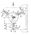
- the venturi rotor structure is vertically oriented and comprises a rotatable central spoiler core 1 which has a spherical triangular cross-section 3.
- Three airfoils 5, 7 and 9 are fixed to the central core 1 by means of support arms 11, 11', 13, 13' and 15, 15'.
- the support arms extend radially outward from the central core 1 at the verticies 17, 19 and 21 of the spherical triangle 3.
- Gaps 23, 25 and 27 are formed between the verticies of the central core 3 and the airfoils 5, 7 and 9.
- the rotation of the central core 1 rotates the shaft 31, which provides a power output through transmission 33, which is supported on a base 35.
- the transmission 33 could be a gear transmission, belt transmission, 5 hydraulic transmission, or any other suitable means for producing a power takeoff from a rotating shaft.
- the axes F5, F7 and F9 of the airfoils 5, 7 and 9, are parallel to the axis C of the central core.
- venturi rotor structure is supported by support posts 37, 39 and at least one additional post (not shown), which are connected to the central core by means of a superstructure 41.
- the central core 1 rotatably held and supported by the superstructure.
- Guy wires may also be used in lieu of or in conjunction with the support posts for providing a stable support structure for the apparatus.
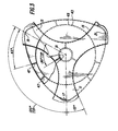
- the central core structure 1 has an outer portion 43 having a spherical-triangular cross-section and an inner portion 45 having a circular cross-section.
- the inner and outer portions are rigidly connected together by means of a plurality of ribs 47.
- the interconnected inner and outer core structure provides a strong, rigid, lightweight central core.
- the inner and outer cores are connected to the central shaft 31 by means of an interconnecting structure 49.
- the airfoils 5, 7 and 9 each have a leading edge 53, which is a knife edge and a trailing edge Ln cross section. 55, which is circular(
- the maximum width of each airfoil w A is approximately equal to the width of the gap wG between the airfoil and the central core. Further, the width of the gap and the maximum width of each airfoil, wA + wG , is equal to the distance D from the central axis C of the central core to the verticies of the central core. In the preferred embodiment, the verticies of the central core are slightly rounded with respect to the actual geometric verticies. There is thus, a small variation in the distances as shown in the drawings because of this difference.
- each airfoil is such that a line L extending between the leading edge and the adjacent vertex of the central :ore is parallel to the line M between the axis C and the axis of the airfoil.
- the core 1 functions as a barrier to the wind stream W directed toward the venturi rotor.
- the central core 1 thus directs the air in the capture area A' towards the airfoil and into the gap 23 between the airfoil 5 and the core 1.
- the flow of air through the gap 23 produces a venturi effect and the directing of the air flow in this manner results in a combination of effects which enhance the rotation of the venturi rotor, thereby producing a simple and efficient generation of power.
- air flow through the gap 23 has a venturi effect.
- This venturi effect cause an increase in air velocity through the gap which results in a substantial increase in the dynamic pressure in the area adjacent the gap and a very substantial decrease in the static pressure in this area.
- Dynamic pressure results in forces in the direction of flow and static pressure results in forces perpendicular to the direction of flow.
- venturi effect thus creates a very low static pressure on the rear or downwind side of the central core 1 and on the opposite or rear surface of the airfoil 5.
- very low static pressure produces a lift effect which sucks or pulls the airfoil 5 and the core 1 in the direction of rotation resulting in additional torque being applied to the core 1, thereby enhancing the rotation of the core.
- the venturi effect of the gap 23 causes an increase in the velocity of air flow through the gap and a decrease in pressure in and behind or downwind of the gap 23.
- the air flow through the gap 23 is thus enhanced first, due to the barrier effect of the central core 1 and secondly, due to the air flowing from the high pressure front aide to the low pressure rear side.
- the kinetic energy transferred from the air flow to the venturi rotor is a function of the mass of air flow in accordance with the equation where:
- the power can be increased by increasing the mass of air flow.
- the mass of air flow can be increased by an increase in the capture area of the venturi rotor.
- the low pressure area in the gap 23 and behind the central core 1 and the airfoil 5 caused by the venturi effect expands the dynamic capture area A' so that it is significantly larger than the geometric capture area A because the low pressure in effect, sucks air from beyond the geometric capture A in order to fill the low pressure areas behind the venturi gap.
- venturi rotor structure As the venturi rotor structure rotates, the various drag and lift forces as well as the areas of high and low pressure around the surfaces of the airfoils and central core is constantly changing. However, the resultant forces on the structure itself, which cause the rotation, remain relatively constant.
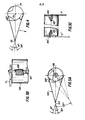
- FIGS 5A, 5B, 5C illustrate an alternative embodiment in which the airfoils are pivotally mounted on the support arms.
- the airfoil 105 is mounted on the support arms 11 and 11 1 by means of a rotatable shaft 107.
- a spring 109 is connected to the shaft 107 through a hole 111 and engages the arm 11 to bias the leading edge 53 of the airfoil in a direction towards the central core.
- centrifugal force tends to push the leading edge of the airfoil away from the central core.
- the centrifugal force is counteracted at least to some extent by the biasing force of the spring to thereby optimize the airfoil orientation.
- Means such as stops, can be provided for limiting the pivotal movement of the airfoil with respect to the arms. Preferably, total movement should be limited to / 120.
- This embodiment is very effective in environments where wind speed is relatively constant because the spring constant can be selected for a particular angular speed. If there is a large variance in wind speed, then the fixed airfoil embodiment is more effective. Other techniques for adjusting the orientation of the air foil can also be used.
- the central core 1 and/or the airfoils 5, 7 and 9 may be constructed as unitary structures or maybe made of a plurality of modular units rigidly fastened together.
- the central core 1 is formed of a plurality of modular units 1A...1E, which are rigidly fastened together by any suitable means such as welding, bolting, riveting, etc.
- the airfoils 5 and 9 are also constructed of a plurality of modular units 5A...5E and 9A...9E. These units are also rigidly fastened together by any suitable means.
- the advantage of the modular construction is that it enables an apparatus of any size to be easily constructed using standard modules. This permits greater flexibility in the manufacture and construction of the apparatus.
- a material should be chosen which has a high strength so that the apparatus can withstand high wind speeds. Furthermore, the material should be lightweight in order to minimize the centrifugal force resulting from the rotation of the apparatus.
- the apparatus is disclosed as being driven by air flow caused by wind, it can be seen that the structure can be used with any type of fluid flow, either gaseous or liquid.
Landscapes
- Engineering & Computer Science (AREA)
- Life Sciences & Earth Sciences (AREA)
- Sustainable Development (AREA)
- Sustainable Energy (AREA)
- Chemical & Material Sciences (AREA)
- Combustion & Propulsion (AREA)
- Mechanical Engineering (AREA)
- General Engineering & Computer Science (AREA)
- Physics & Mathematics (AREA)
- Fluid Mechanics (AREA)
- Wind Motors (AREA)
Applications Claiming Priority (2)
| Application Number | Priority Date | Filing Date | Title |
|---|---|---|---|
| US06/535,099 US4537559A (en) | 1983-09-23 | 1983-09-23 | Venturi rotor apparatus for the generation of power |
| US535099 | 1983-09-23 |
Publications (1)
| Publication Number | Publication Date |
|---|---|
| EP0140566A1 true EP0140566A1 (de) | 1985-05-08 |
Family
ID=24132833
Family Applications (1)
| Application Number | Title | Priority Date | Filing Date |
|---|---|---|---|
| EP84306420A Withdrawn EP0140566A1 (de) | 1983-09-23 | 1984-09-20 | Rotor |
Country Status (7)
| Country | Link |
|---|---|
| US (1) | US4537559A (de) |
| EP (1) | EP0140566A1 (de) |
| JP (1) | JPS60243378A (de) |
| KR (1) | KR850003192A (de) |
| AU (1) | AU3321284A (de) |
| BR (1) | BR8404760A (de) |
| ZA (1) | ZA847456B (de) |
Cited By (2)
| Publication number | Priority date | Publication date | Assignee | Title |
|---|---|---|---|---|
| US5231019A (en) * | 1984-05-11 | 1993-07-27 | Ciba-Geigy Corporation | Transformation of hereditary material of plants |
| EP2174004A4 (de) * | 2007-06-27 | 2013-11-20 | Grocon Innovations Pty Ltd | Windturbine mit luftstromablenker |
Families Citing this family (14)
| Publication number | Priority date | Publication date | Assignee | Title |
|---|---|---|---|---|
| GB8626347D0 (en) * | 1986-11-04 | 1986-12-03 | Bicc Plc | Wind energy convertor |
| US5083901A (en) * | 1989-05-08 | 1992-01-28 | Griffin Jr Ralph C | Electricity generating wind turbine |
| RU2140013C1 (ru) * | 1998-11-30 | 1999-10-20 | Александр Иванович Веремеенко | Ветроколесо |
| NL1018281C2 (nl) * | 2001-06-13 | 2002-12-16 | Ngup Holding B V | Rotor, windturbine en samenstel daarvan. |
| NL1019855C2 (nl) * | 2001-06-13 | 2002-12-16 | Ngup Holding B V | Rotor, windturbine en samenstel daarvan. |
| US7425776B2 (en) * | 2006-06-21 | 2008-09-16 | Ketcham John C | Multi-cylinder wind powered generator |
| CN101984254B (zh) * | 2010-11-23 | 2012-09-05 | 吴要明 | 低速风能动力发电机 |
| CN102102636A (zh) * | 2011-03-14 | 2011-06-22 | 王忠明 | 一种带有多功能风叶以及风轮的垂直轴风力发电机组 |
| CN102367782B (zh) * | 2011-09-28 | 2014-06-11 | 上海庆华蜂巢建材有限公司 | 一种垂直轴风力发电机 |
| CN102364091A (zh) * | 2011-11-18 | 2012-02-29 | 长兴宇峰机电有限公司 | 风能发电机的六叶风筒 |
| CN102434385A (zh) * | 2011-12-31 | 2012-05-02 | 杨道彤 | 兆瓦级风力发电系统风能转换装置 |
| US10033314B2 (en) * | 2013-05-29 | 2018-07-24 | Magnelan Technologies Inc. | Modified Halbach array generator |
| US20150211482A1 (en) * | 2014-01-08 | 2015-07-30 | Theodore Radisek | Resilient blade wind turbine |
| US20220356870A1 (en) * | 2021-05-06 | 2022-11-10 | Noel Richard Potter | Dynamic wind turbine rotational speed control |
Citations (5)
| Publication number | Priority date | Publication date | Assignee | Title |
|---|---|---|---|---|
| DE604333C (de) * | ||||
| FR732018A (fr) * | 1931-12-31 | 1932-09-12 | Turbine aérienne et hydraulique | |
| FR929721A (fr) * | 1946-06-25 | 1948-01-06 | Rotor électro-éolien trialaire à axe vertical | |
| DE3003270A1 (de) * | 1980-01-28 | 1981-08-06 | Alfred 1000 Berlin Goedecke | Windkraftmaschine mit einem um eine senkrechte achse drehbaren windrotor |
| DE3004669A1 (de) * | 1980-02-08 | 1981-08-13 | Erich 6100 Darmstadt Herter | Windturbine |
Family Cites Families (9)
| Publication number | Priority date | Publication date | Assignee | Title |
|---|---|---|---|---|
| FR502616A (fr) * | 1919-08-14 | 1920-05-21 | Francois Victor Denhaut | Turbine aérienne |
| DE860930C (de) * | 1948-10-02 | 1952-12-29 | Ernst Dipl-Ing Jahnke | Windkraftmaschine |
| DE2051579A1 (de) * | 1970-10-21 | 1972-04-27 | Bruns F | Turbine mit Bruns-Bernoullischem Kanteneffekt |
| US4015911A (en) * | 1974-01-09 | 1977-04-05 | Arthur Darvishian | Higher efficiency wind motor with receptors of diminished drag characteristics |
| FR2298706A1 (fr) * | 1975-01-22 | 1976-08-20 | Sicard Charles | Dispositif tournant actionne par un fluide en mouvement |
| US4037989A (en) * | 1975-05-12 | 1977-07-26 | Huther Jerome W | Vertical axis wind turbine rotor |
| US4004861A (en) * | 1975-06-13 | 1977-01-25 | Charl Soules | Wind driven prime mover |
| CA1045038A (en) * | 1977-06-06 | 1978-12-26 | James Cameron | Vertical axis wind turbine |
| US4209281A (en) * | 1978-07-20 | 1980-06-24 | Edmunds William A | Wind driven prime mover |
-
1983
- 1983-09-23 US US06/535,099 patent/US4537559A/en not_active Expired - Fee Related
-
1984
- 1984-09-18 AU AU33212/84A patent/AU3321284A/en not_active Abandoned
- 1984-09-20 EP EP84306420A patent/EP0140566A1/de not_active Withdrawn
- 1984-09-21 BR BR8404760A patent/BR8404760A/pt unknown
- 1984-09-21 JP JP59196964A patent/JPS60243378A/ja active Pending
- 1984-09-21 ZA ZA847456A patent/ZA847456B/xx unknown
- 1984-09-22 KR KR1019840005816A patent/KR850003192A/ko not_active Ceased
Patent Citations (5)
| Publication number | Priority date | Publication date | Assignee | Title |
|---|---|---|---|---|
| DE604333C (de) * | ||||
| FR732018A (fr) * | 1931-12-31 | 1932-09-12 | Turbine aérienne et hydraulique | |
| FR929721A (fr) * | 1946-06-25 | 1948-01-06 | Rotor électro-éolien trialaire à axe vertical | |
| DE3003270A1 (de) * | 1980-01-28 | 1981-08-06 | Alfred 1000 Berlin Goedecke | Windkraftmaschine mit einem um eine senkrechte achse drehbaren windrotor |
| DE3004669A1 (de) * | 1980-02-08 | 1981-08-13 | Erich 6100 Darmstadt Herter | Windturbine |
Cited By (4)
| Publication number | Priority date | Publication date | Assignee | Title |
|---|---|---|---|---|
| US5231019A (en) * | 1984-05-11 | 1993-07-27 | Ciba-Geigy Corporation | Transformation of hereditary material of plants |
| US6201169B1 (en) | 1984-05-11 | 2001-03-13 | Novartis Finance Corporation | Transformation of hereditary material of Brassica plants and cells |
| US6603065B2 (en) | 1984-05-11 | 2003-08-05 | Syngenta Invest Corp | Transformation of hereditary material of plants |
| EP2174004A4 (de) * | 2007-06-27 | 2013-11-20 | Grocon Innovations Pty Ltd | Windturbine mit luftstromablenker |
Also Published As
| Publication number | Publication date |
|---|---|
| BR8404760A (pt) | 1985-08-13 |
| KR850003192A (ko) | 1985-06-13 |
| AU3321284A (en) | 1985-03-28 |
| JPS60243378A (ja) | 1985-12-03 |
| ZA847456B (en) | 1985-08-28 |
| US4537559A (en) | 1985-08-27 |
Similar Documents
| Publication | Publication Date | Title |
|---|---|---|
| EP0140566A1 (de) | Rotor | |
| EP0679805B1 (de) | Windturbine mit senkrechter Achse | |
| US4359311A (en) | Wind turbine rotor | |
| US5246342A (en) | Wind rotor apparatus | |
| US7347660B2 (en) | Cross-flow wind turbine | |
| US4838757A (en) | Wind turbine system using a savonius type rotor | |
| US7993096B2 (en) | Wind turbine with adjustable airfoils | |
| US5711653A (en) | Air lifted airfoil | |
| Reupke et al. | Slatted-blade Savonius wind-rotors | |
| EP1835173A2 (de) | Wirbelerzeugender zyklischer Propeller | |
| US5599168A (en) | Wind turbine adaptable to wind direction and velocity | |
| US8162589B2 (en) | Moving fluid energy recovery system | |
| JPS5941679A (ja) | 風力エネルギを別種のエネルギに変換する装置 | |
| CN113503223A (zh) | 一种聚风装置和聚风装置驱动的设备 | |
| JP2004084590A (ja) | ウイングレット付き風車 | |
| JPS5928754B2 (ja) | 垂直軸風車の翼体 | |
| EP1808599A2 (de) | Flüssigkeitsturbine mit axialer Drehachse | |
| JP2010520414A (ja) | ハブレス風車 | |
| US20110070083A1 (en) | Streamlined Wind Turbine Optimized for Laminar Layer | |
| Van Holten | Concentrator systems for wind energy, with emphasis on tipvanes | |
| US4125343A (en) | Planetary blade turbine | |
| EP0070857A1 (de) | Von flüssigkeit-angetriebener rotor | |
| US6602054B1 (en) | Fluid motor apparatus for amplifying thrust | |
| KR20020005556A (ko) | 통풍홈 부착 사보니우스풍차 회전날개 | |
| CN85100629A (zh) | 一种产生动力的文杜里转动器装置 |
Legal Events
| Date | Code | Title | Description |
|---|---|---|---|
| PUAI | Public reference made under article 153(3) epc to a published international application that has entered the european phase |
Free format text: ORIGINAL CODE: 0009012 |
|
| AK | Designated contracting states |
Designated state(s): AT BE CH DE FR GB IT LI LU NL SE |
|
| RAP1 | Party data changed (applicant data changed or rights of an application transferred) |
Owner name: HERRMANN, ANNA Owner name: HERRMANN, CHRISTIAN WOLFGANG |
|
| 17P | Request for examination filed |
Effective date: 19860107 |
|
| 17Q | First examination report despatched |
Effective date: 19860911 |
|
| STAA | Information on the status of an ep patent application or granted ep patent |
Free format text: STATUS: THE APPLICATION IS DEEMED TO BE WITHDRAWN |
|
| 18D | Application deemed to be withdrawn |
Effective date: 19870324 |
|
| RIN1 | Information on inventor provided before grant (corrected) |
Inventor name: HERRMANN, CHRISTIAN WOLFGANG |