EP0140721A1 - Einrichtung zum Formen von Betonerzeugnissen mit unverzüglicher Entformung - Google Patents
Einrichtung zum Formen von Betonerzeugnissen mit unverzüglicher Entformung Download PDFInfo
- Publication number
- EP0140721A1 EP0140721A1 EP84401622A EP84401622A EP0140721A1 EP 0140721 A1 EP0140721 A1 EP 0140721A1 EP 84401622 A EP84401622 A EP 84401622A EP 84401622 A EP84401622 A EP 84401622A EP 0140721 A1 EP0140721 A1 EP 0140721A1
- Authority
- EP
- European Patent Office
- Prior art keywords
- face
- frame
- tool according
- spar
- partitions
- Prior art date
- Legal status (The legal status is an assumption and is not a legal conclusion. Google has not performed a legal analysis and makes no representation as to the accuracy of the status listed.)
- Withdrawn
Links
- 238000000465 moulding Methods 0.000 title claims abstract description 8
- 238000005192 partition Methods 0.000 claims abstract description 60
- 230000000295 complement effect Effects 0.000 claims description 6
- 239000002184 metal Substances 0.000 claims description 3
- 230000006835 compression Effects 0.000 claims 1
- 238000007906 compression Methods 0.000 claims 1
- 239000012729 immediate-release (IR) formulation Substances 0.000 claims 1
- 208000031968 Cadaver Diseases 0.000 description 5
- 238000005299 abrasion Methods 0.000 description 3
- 244000245420 ail Species 0.000 description 3
- 239000004744 fabric Substances 0.000 description 3
- 229910001208 Crucible steel Inorganic materials 0.000 description 2
- 240000008042 Zea mays Species 0.000 description 2
- 210000005069 ears Anatomy 0.000 description 2
- 241000826860 Trapezium Species 0.000 description 1
- 230000000712 assembly Effects 0.000 description 1
- 238000000429 assembly Methods 0.000 description 1
- 238000005056 compaction Methods 0.000 description 1
- 238000006073 displacement reaction Methods 0.000 description 1
- 230000000694 effects Effects 0.000 description 1
- 238000009434 installation Methods 0.000 description 1
- 238000012423 maintenance Methods 0.000 description 1
- 238000004519 manufacturing process Methods 0.000 description 1
- 238000012986 modification Methods 0.000 description 1
- 230000004048 modification Effects 0.000 description 1
- 238000012856 packing Methods 0.000 description 1
Images


Classifications
-
- B—PERFORMING OPERATIONS; TRANSPORTING
- B28—WORKING CEMENT, CLAY, OR STONE
- B28B—SHAPING CLAY OR OTHER CERAMIC COMPOSITIONS; SHAPING SLAG; SHAPING MIXTURES CONTAINING CEMENTITIOUS MATERIAL, e.g. PLASTER
- B28B7/00—Moulds; Cores; Mandrels
- B28B7/0002—Auxiliary parts or elements of the mould
- B28B7/0014—Fastening means for mould parts, e.g. for attaching mould walls on mould tables; Mould clamps
-
- B—PERFORMING OPERATIONS; TRANSPORTING
- B28—WORKING CEMENT, CLAY, OR STONE
- B28B—SHAPING CLAY OR OTHER CERAMIC COMPOSITIONS; SHAPING SLAG; SHAPING MIXTURES CONTAINING CEMENTITIOUS MATERIAL, e.g. PLASTER
- B28B7/00—Moulds; Cores; Mandrels
- B28B7/0029—Moulds or moulding surfaces not covered by B28B7/0058 - B28B7/36 and B28B7/40 - B28B7/465, e.g. moulds assembled from several parts
-
- B—PERFORMING OPERATIONS; TRANSPORTING
- B28—WORKING CEMENT, CLAY, OR STONE
- B28B—SHAPING CLAY OR OTHER CERAMIC COMPOSITIONS; SHAPING SLAG; SHAPING MIXTURES CONTAINING CEMENTITIOUS MATERIAL, e.g. PLASTER
- B28B7/00—Moulds; Cores; Mandrels
- B28B7/28—Cores; Mandrels
Definitions
- the present invention relates to a tool for molding concrete products with immediate mold release.
- Such a tool comprising, on the one hand, a female tool comprising a frame inside which are arranged open cells on each side of the frame, means for fixing the frame to the press, and a certain number of cores. carried by bars fixed to the frame which extend in the plane of the frame in the vicinity of one of the open sides of the cells, and, on the other hand, a male part comprising a body and profiles made integral with one faces of the body by means of candles the dimensions of which are recessed relative to those of the profiles, the latter being dimensioned and mutually arranged so as to be able to penetrate together into all the openings remaining in the frame between the walls of the cells, cores and bars.
- the partitions, certain surfaces of the longitudinal members, the bars and the cores are elements liable to wear out because they are exposed to friction from the concrete during molding.
- the object of the invention is to propose a tool of the aforementioned type, in which wear elements are fixed to the frame in a removable and nevertheless precise manner.
- the present invention thus relates to a female tool for molding concrete products for immediate demoulding, comprising a frame to which are attached a certain number of wear elements delimiting, inside the frame, open cells on each side of the frame , these wear elements comprising surfaces carried by the frame facing the cells, partitions separating the cells between them, and cores carried by bars arranged in the plane of the frame in the vicinity of one of the open sides of the cells and fixed at their ends to two opposite side members of the frame.
- the tooling is characterized in that the wear elements comprise removable wear elements which, in the vicinity of each spar, are interposed between, on the one hand, a profiled bearing formed in a carried notch by the beam so as to overlap a base face of the beam and a face of the beam turned towards the inside of the frame, and, on the other hand, a face of a locking body forming part of a locking device comprising , in addition, means bearing on the frame to urge said face of the body in abutment capable of sliding against the removable wear element, so as to apply the latter against said bearing while allowing it to position itself freely.
- the wear element is no longer permanently secured to the spar. On the contrary, by loosening the locking body, it can be extracted from between the seat and the body. However, in the service position, the wear element is precisely positioned against the bearing.
- the wear element is correctly positioned and that, consequently, the product produced will have the desired profile.
- the tool for molding concrete products comprises a female part 1 and a male part 2.
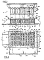
- the female part 1 (FIGS. 1 to 12) comprises a generally rectangular frame 3 made up of two longitudinal members 4a and 4b extending along the lengths of the rectangle, and two cross-members 6 joining the ends of the longitudinal members two by two. sleepers 6 carry on their face directed towards the outside of the frame 3 ears 7 intended to be fixed to the press (not shown).
- the female part 1 arranged in service along a horizontal plane, can be moved between a low position in which it rests on a board 8 (FIG. 1), and a high position in which it is, relative to the board 8, at a distance at least equal to the height of the side members 4a and 4b.
- the board 8, which is mounted on rollers is locked against any displacement on the rollers.
- the longitudinal members 4a and 4b, as well as the crosspieces 6, form, by their upper face opposite to the board 8, a flat and horizontal tabular surface 201 which, when loading concrete, supports a loading drawer constituted by an elongated hopper parallel to the direction of the side members and performing a back-and-forth movement above the frame in the direction perpendicular to the side members 4a and 4b.
- the crosspieces 6 are made of cast steel with a U-shaped profile opening towards the outside of the frame.
- the lower wing of the U is made up of the ears 7.
- the outer face of the upper wing of the U is treated to resist abrasion and contributes to constituting the tabular surface 201. It carries a guide rib 202 to guide the loading drawer during its movement of va- back and forth above the frame.
- the frame 3 has inside its wear elements delimiting cells 14 open on each side of the frame.
- These wear elements include partitions 213 perpendicular to the plane of the frame and each extending from one spar to the other parallel to the crosspieces 6.
- the wear elements also include the internal face 16 of the longitudinal members 4a, 4b which constitutes the end faces of the cells 14.
- each of the cells 14 defined between the partitions 213 are mounted two rows of cores 41 arranged parallel to the crosspieces 6 and forming part of the wear elements.
- the cores 41 are welded to a common strip 142 having a vertically elongated profile; the bars 142 are substantially adjacent to the plane of the tabular surface 201, on the side of the interior of the cells 14.
- Each cell thus has in the plane of the tabular surface three comb-shaped openings between the faces 16, the partitions 213, the cores 41 and the bars 142.
- the male tool 2 ( Figures 1 and 13), which cooperates with the cells 14 through these openings comprises a frame 249 to which are fixed by means of candles 254 profiles 252 dimensioned and mutually disposed so as to be able to penetrate together each in one of said openings.
- Each profile 252 and an associated candle 254 are constituted by a one-piece foundry piece.
- Each candle 254 is constituted by a rectangular fabric which in service is parallel to the partitions 213 and 247.
- each assembly constituted by a profile 252 and a candle 254 is fixed to the body 249 by two screws 261.
- the female tool 1 In the low position, the female tool 1 is closed below by the board, the cells 14 are filled with concrete by the loading drawer not shown, serving as a scraper by reciprocating movement on the tabular surface 201, so that the level of the concrete in the cells 14 is flush with said surface.
- the female tool 1 is then subjected to vibrations aimed at carrying out a first compaction of the concrete.
- the male tool 2 is lowered towards the female tool, the comb profiles of which penetrate into the cells 14 through the openings left free between bars 142, cores 41 and partitions 213 and 247.
- the level of the concrete is substantially reduced to that of the underside of the bars 142.
- the male tool 2 being held in this position, it is removed by lifting the female tool 1. After removal of the male tool 2, the board 8 is removed with the demolded products.
- the ends of the bars 142 are fixed in notches 143 formed in each spar 4a or 4b so as to open both in the tabular surface 201 and in the internal wall 16 of each spar 4a or 4b (see Figures 1 to 4 , 19.20).
- Each notch 143 (FIG. 19) has around its opening in the wall 16 facing the inside of the frame, a face 161 parallel to the tabular surface 201, and two opposite lateral faces 162 perpendicular to the face 161.
- the faces 161 and 162 are parallel to the longitudinal direction of the bars 142.
- the faces 161 and 162 are projecting relative to the rear part 163 of the notch 143 which is roughly foundry.
- each end of the strip 142 is interposed between a bearing formed by a face 162 and the adjacent area of the face 161, and a locking body formed by a corner 164 whose profile, seen according to the longitudinal direction of the bars, is an isosceles trapezium whose small base 166 is turned towards the inside of the notch 143.
- each notch 143 receives two ends belonging to two adjacent bars 142 and carrying the cores of the same cell 14. Each of these two ends is in the service position applied against the bearing associated with a respective one of the faces 162. Each end carries on its face turned towards the inside of the recess, that is to say towards the other end of the bar occupying the same notch, a bevel 166 whose obliquity is such that the faces oblique 168 of the corner 164 can be supported flat each on one of the bevels 167 when the two ends of the bar 142 are pressed flat against the faces 162.
- the corner 164 is part of a locking device further comprising two tie rods 169 (which in the example described are bolts with a countersunk head in the large base of the trapezoid) which extend in a transverse direction to the plane of the frame 3 and are each threaded into a bore 171 of the corner 164 and a corresponding bore 172 formed through a fabric 231 which delimits the bottom of the notch 143 and which will be described later.
- tie rods 169 which in the example described are bolts with a countersunk head in the large base of the trapezoid
- Each partition 213 constitutes, like the bar-core assemblies, a removable wear element which, in the vicinity of each spar 4a or 4b, is interposed between on the one hand a profiled surface 207 (FIG. 9) formed in a notch 204, 208 carried by the beam 4a or 4b and on the other hand, a face 212 of a locking body 211 forming part of a locking device 209 further comprising means 227 for biasing said face 212 in support capable of sliding against the partition so as to apply the latter against the profiled surface 207.
- Each notch of each spar 4a or 4b comprises a guide groove 204 formed vertically in the internal wall 16 of the spar, and in which is engaged a lateral end zone 203 of the partition 213 (see also partition 213a in FIG. 3 where two partitions 213 of FIG. 1 are shown 213a and 213b, shown differently).
- Each notch comprises, in addition to the groove 204, a housing 208 which overlaps the internal face 16 and the tabular surface 201 and into which the groove 204 opens.
- the lateral end zone 203 (FIGS. 9 and 10) has a triangular spout 217 projecting into the housing 208.
- the spout 217 is delimited on the side opposite the tabular surface 201 by a shoulder 206 intended to bear on the bearing 207 which is parallel to the surface 201 and constitutes a sort of threshold of the housing 208 at the outlet of the groove 204.
- the spout 217 is delimited by a bevel 214 connected by an obtuse angle to an upper edge 216 of the partition and which cooperates by means of support capable of sliding with the face 212, of corresponding obliquity, of the locking body 211.
- the oblique face 212 constitutes the bottom of a slot 218 which receives in service the spout 217 with a free but precise adjustment.
- the body 211 has on either side of the slot 218 two faces 219 which in service are in the extension of the wall 16 of the spar.
- the body 211 also has two parallel and opposite flat side faces 221 by which it is in guided service between two flat profiled faces 222 parallel to the partitions 213 and provided at the entrance to the housing 208 on either side of the span 207
- each partition 213 is rigorously positioned with respect to the beams 4b relative to any movement parallel to the longitudinal direction of the beams.
- a tolerance compensator 223 constituted by a flexible element, for example made of rubber, with a U-shaped profile, is interposed between each end zone 203 of the partitions 213 and the groove 204 which is associated with it .
- the locking body 211 also has a flat rear face 224 applied in service against a face 226 of the housing 208 vertical and perpendicular to the faces 222.
- the removable means 209 further comprise a bolt 227 directed vertically and passing through the body 211 and the bottom of the housing 208 so as to bear on the beam 4b to urge, in the direction of mutual support of the oblique face 212 and the oblique edge 214, the locking body 211 guided transversely to the plane of the frame between the faces 222 and 226.
- the dimensions are such that a planar upper face 228 of the locking body 211 is substantially in the plane of the tabular surface 201 when the bolt 227 is tightened, while a face lower plane 229 of the body 211 is then moved away from the bearing surface 207.
- the notches 143 and the housings 208 have substantially the same depth measured perpendicular to the plane of the frame 3 and are separated, by a canvas 231, from a series of recesses 232 opening on the outside of the frame 3 to give access to bolts 169 and 227.
- the recesses 232 are separated by partitions 233.
- the recesses 232 are connected to the notches 143 and to the housings 208, respectively by the holes 172 for the passage of the bolts 169 and by holes 234 for the passage of bolts 227.
- the recesses 232 are adjacent to a substantially closed box 236 extending over the entire length of the spar.
- the closure wall, turned towards the outside of the frame, of the box 236 is interrupted to allow bolts 26 to be reached, making it possible to fix the cross-member 6 against the surface d end of the spar.
- One of the bolts 26 at each end of the side members 4a or 4b is accessible by a recess 232 adjacent to this end.
- each end of the longitudinal members 4a or 4b is constituted by a planar web 237 which is transverse to the longitudinal direction of the longitudinal member and intended to be applied against the cross-member 6.
- a planar web 237 which is transverse to the longitudinal direction of the longitudinal member and intended to be applied against the cross-member 6.
- three holes 238 are made for the passage of the bolts 26, two of the holes 238 being substantially larger to interpose between them and the rod of the bolt 26 a tubular centering pin 239 (FIG. 3).
- the veil 237 at each end of each spar has a clearance 241 connected to the internal wall 16 and delimited opposite to it by a vertical shoulder 242 turned towards the inside of the frame 3.
- the clearance 241 is enlarged towards the outside of the frame by a step 243 above which opens a bore 244 with an axis parallel to the longitudinal direction of the spar.
- the clearance 241 forms with the internal wall 246 of the adjacent cross-member 6, a guide groove receiving in service the lateral end zone 203 of an end partition 247 which is applied against the wall 246 of the cross-member 6 to separate the latter of the cell 14 which is adjacent to it.
- the wall 246 has, opposite the clearance 241, a recess 248 intended to receive one of the wings of the tolerance compensator 223 and thus allow perfect support of the partition 247 against the cross-member 6 (left part of FIG. 3).
- the partitions 247 are identical to the partitions 213, and their shoulder 206 is in service pressed against the step 243 while their oblique edge 214 partially covers the bore 244.
- a cylindrical part 262 of a locking body 263 In the bore 244 is mounted to slide a cylindrical part 262 of a locking body 263. From the completely cylindrical zone 262 (FIG. 7), the body 263 is progressively thinned by a plane bevel 264 constituting an oblique face intended to cooperate by support capable of sliding with the bevel 214 of the partition 247 in order to apply the shoulder 206 against the step 243, which thus constitutes a bearing surface having a role similar to the spans 207.
- room 263 On the other side of the zone 262, room 263 comprises a male threaded endpiece 266 which passes through the vertical core of the crosspiece 6 and cooperates on the other side of the latter with a pulling nut 267 (FIG. 3).
- the tool further comprises a table 272 fixed to the beam 4b and having a rectangular upper face 273 which is in the plane of the tabular face 201 of the frame 3 and is used to support the loading drawer during its limit switch opposite to its rest position.
- the face 273 is bordered by two lateral fins 274 which in service extend the fins 202 of the crosspieces 6, and by an end fin 276 along its edge opposite the spar 4b.
- the table 272 (FIG. 12) is terminated by a lip 277 supported by means of a flexible seal 278 against a lowered longitudinal edge 279 of the spar 4b.
- the table 272 On its underside, the table 272 carries two consoles 281 intended to be applied each against two bosses 282 carried by the wall closing the box 236 on the outside of the frame 3.
- Each console 281 on the one hand and the two bosses 282 which are associated on the other hand, have respectively vertical faces 283, 284 parallel to the longitudinal direction of the spar, intended to be in mutual support and having horizontal ridges of complementary profiles.
- Each pair of bosses 282 delimits between itself a slide 286 in which the heads 287 of two bolts 288 (only one is shown) can slide but are immobilized in rotation.
- the rod 289 of the bolts 288 protrudes between the bosses 282 and is engaged in a bore 28 of the console 281 to cooperate with a nut 290 bearing behind the wall carrying the ridged surface 283.
- the longitudinal members 4a, 4b comprise a core 291 having a general U-shaped profile opening towards the outside of the frame 3, and wear tiles 292 fixed to the core 291 and bearing the face 16 of the side members facing the inside of the frame and the part of the tabular face 201 associated with the side members.
- the core 291 is made of cast steel having good weldability and good flexural strength, but not necessarily abrasion resistant.
- the tiles 292 are made of abrasion resistant metal.
- the rear face of the tiles 292 includes, near its lower edge, a boss 293 capable of pressing stably against a corresponding boss 294 of the core 291.
- the upper wing of the core 291 has a stop flange 296 extending to the tabular surface 201 and against which is pressed the edge of the tiles 292 opposite the boss 293.
- the rim 296 carries the lowered edge 279 for fixing the table 272.
- Each tile 292 carries on its rear face a captive nut 299 in the shape of a pyramid trunk sliding in a dovetail groove of the corresponding tile and cooperating with a screw 301 - passing through the core 291 so as to make the two effective supports mentioned above.
- the upper wing of the core 291 and the tile 292 still carry bosses 297, 298 providing them with mutual support along a plane parallel to the tabular surface 201.
- FIG. 15 there is a tile 292 at each end of cell 14.
- the Figures 15 to 17 show that the notches 143 for fixing the bars 142 are carried by the tiles 292, their rear face however being delimited by the flange 296 of the core 291.
- the bolts 169 which cooperate with a locking body 164 essentially unchanged, pass through the tile 292 and the core 291 to bear under the upper wing of the core 291.
- the bolts 169 contribute to the fixing the tiles 292 to the core 291 while ensuring the mutual support of the bosses 297 and 298, as allowed by the assembly capable of sliding between the nut 299 and the tile.
- the holes for the bolts 169 through the tiles and / or through the core 291 are larger than the stem of the bolts 169 to allow the nut 299 and the screw 301 to freely apply the tiles against its vertical bearing surfaces 294, 296.
- the locking body 164 constitutes for the tile 292 a locking body capable of indirect-sliding support whose purpose is to apply the tile against the boss 298 while allowing free positioning against the ranges 295, 296.
- the tiles 292 define therebetween, for guiding the lateral end zone 203 of the partitions 213, the grooves 204 whose bottom (FIG. 18) is formed by the core 291 (FIG. 17).
- each partition fixing notch further comprises a space 302 (FIG. 16) left free between the upper wing of the core 291 and the tile 292 because the latter has a shape on its rear face. matching that of the tabular face 201 and the notch 143.
- each partition 213 projects into the space 302. Its shoulder 206 is applied against the bearing surface 207 formed by the upper face of the upper wing of the core 291.
- the spout 217 is no longer triangular, but rectangular so as to present, slightly recessed from the upper edge 216 of the partition, a shouldered edge 214 against which two locking bodies 211 are supported each consisting of a lateral overhang that presents each tile on each side in the plane of the tabular surface 201. It is understood that thus, the bolts 169 also ensure the locking of the partitions 213.
- the support of the overhangs 211 is capable of sliding on the shouldered edge 214 in this direction that the support between overhangs 211 and edges 214 can take place in different relative positions determined by the positioning of the partition 213 in the groove 204.
- the end partitions 247 are identical to the partitions 13, and positioned in the same way except that their guide grooves are defined between the cross-member 6 and the adjacent tile 292, and that their ver- rusting is ensured only by a single overhang 211 in the vicinity of each spar 4a or 4b.
- the faces 162 of the notches 143 are oblique and undercut relative to the opening of the notch 143 in the tabular surface 201; in addition, the bar ends 142 have a profile defining two faces which can be applied at the same time to a face 162 and to the face 161.
- the locking body 164 comprises a very firm rubber block 173 enclosed in two metal half-shells 174.
- Each half-shell 174 comprises a wing 176 interposed between the block 173 and the bar 142 - and a wing 177 situated on the side of the opening of the notch 143 in the wing 9.
- the two wings 176 are fixed, for example glued to block 173, while the two wings 177 are free relative to block 173 and sliding relative to one another in the transverse direction to wings 176.
- the wings 176 have a rounded concave profile forming a hollow 178 bordered on each side by substantially symmetrical projections 179.
- the bars 142 have on the side of their ends facing the body 164 a convex profile complementary to the concave profile of the wings 176.
- the boss 160 is crossed by a light 181 opening into the fabric 231.
- the light 181 is large enough to allow the passage of the body 173 in a direction perpendicular to the plane of the frame.
- the outline of the lumen 181 is shown in phantom in Figure 2.
- the body 164 is pushed in the same direction as that of the introduction, which drives the body 164 through the light 181.
- the body 164 is collected from the recess 232 adjacent to the notch 143 considered.
- the improvements in accordance with the present invention facilitate the manufacture, maintenance and use of the tool while benefiting from the dimensional precision of the products produced.
- This is how the partitions 213, 247 are rigorously positioned and can be interchanged from the top of the female part without disassembling the frame.
- the table 272 it can be placed very precisely in the extension of the tabular surface 201 while being fixed very stably by interlocking the complementary grooves provided on the surfaces 283 and 284.
Landscapes
- Engineering & Computer Science (AREA)
- Manufacturing & Machinery (AREA)
- Chemical & Material Sciences (AREA)
- Ceramic Engineering (AREA)
- Mechanical Engineering (AREA)
- Workshop Equipment, Work Benches, Supports, Or Storage Means (AREA)
- Moulds, Cores, Or Mandrels (AREA)
Applications Claiming Priority (4)
| Application Number | Priority Date | Filing Date | Title |
|---|---|---|---|
| FR8312977 | 1983-08-05 | ||
| FR8312977A FR2550122B1 (fr) | 1983-03-01 | 1983-08-05 | Outillage pour mouler des produits en beton a demoulage immediat |
| FR8403673A FR2560811A2 (fr) | 1984-03-09 | 1984-03-09 | Outillage pour mouler des produits en beton a demoulage immediat |
| FR8403673 | 1984-03-09 |
Publications (1)
| Publication Number | Publication Date |
|---|---|
| EP0140721A1 true EP0140721A1 (de) | 1985-05-08 |
Family
ID=26223553
Family Applications (1)
| Application Number | Title | Priority Date | Filing Date |
|---|---|---|---|
| EP84401622A Withdrawn EP0140721A1 (de) | 1983-08-05 | 1984-08-03 | Einrichtung zum Formen von Betonerzeugnissen mit unverzüglicher Entformung |
Country Status (2)
| Country | Link |
|---|---|
| EP (1) | EP0140721A1 (de) |
| DE (1) | DE140721T1 (de) |
Cited By (8)
| Publication number | Priority date | Publication date | Assignee | Title |
|---|---|---|---|---|
| FR2579511A2 (fr) * | 1984-06-01 | 1986-10-03 | Accetta Andre | Machine pour la production de blocs a batir en terre stabilisee |
| EP0262278A1 (de) * | 1986-10-01 | 1988-04-06 | André Accetta | Maschine zum Herstellen von Bausteinen aus stabilisierter Erde |
| FR2682634A1 (fr) * | 1991-10-22 | 1993-04-23 | Balbinot Ets | Dispositif pour le moulage vibrant de produits en beton, tels que parpaings, paves ou elements de bordure de trottoir. |
| EP0730936B1 (de) * | 1995-03-08 | 2000-10-04 | KOBRA FORMEN-UND ANLAGENBAU GmbH | Rüttelform |
| US20100225023A1 (en) * | 2007-07-23 | 2010-09-09 | S.A.C.M.E. Spa | Machine and method to produce structural elements for the building trade made of cement material, having one or more polymer material inserts |
| NL2005214C2 (nl) * | 2010-08-11 | 2012-02-14 | Beheermij De Boer Nijmegen Bv | Een van een afdichtinrichting voorzien vormbakdeel, alsmede een dergelijke afdichtinrichting en werkwijze voor de toepassing daarvan. |
| US20120192522A1 (en) * | 2011-02-02 | 2012-08-02 | Jay Johnson | Molds for producing concrete blocks with roughened surfaces; blocks made therefrom; and methods of use |
| DE102014002965A1 (de) | 2013-07-30 | 2015-02-05 | Leybold Optics Gmbh | Schichtsystem eines transparenten Substrats sowie Verfahren zur Herstellung eines Schichtsystems |
Citations (15)
| Publication number | Priority date | Publication date | Assignee | Title |
|---|---|---|---|---|
| DE113875C (de) * | 1899-04-20 | |||
| GB178370A (en) * | 1921-07-07 | 1922-04-20 | John Thomas Browne | Improvements in means for use in the moulding of concrete building blocks |
| GB374596A (en) * | 1931-05-11 | 1932-06-16 | Herman Peace | Improvements in or relating to moulds for the manufacture of concrete blocks |
| US2608739A (en) * | 1951-09-06 | 1952-09-02 | John H Minton | Machine for molding drain tile |
| US3387343A (en) * | 1966-11-09 | 1968-06-11 | Westland Aircraft Ltd | Pipe-clip arrangement |
| DE2133947A1 (de) * | 1971-07-08 | 1973-01-18 | Krupp Gmbh | Fuellraumwechselfutter eines formkastens zur herstellung von einhand-kunststeinrohlingen |
| DE2240582A1 (de) * | 1972-08-18 | 1974-02-28 | Picard Fa Carl Aug | Futter fuer pressformen zum herstellen von kunststeinen |
| FR2210928A5 (de) * | 1972-12-18 | 1974-07-12 | Minato Andre | |
| FR2301716A1 (fr) * | 1975-02-21 | 1976-09-17 | Hotz Roger | Dispositif de fixation |
| FR2365418A1 (fr) * | 1976-09-24 | 1978-04-21 | Garin Guy | Outillage en elements interchangeables pour moulage de blocs de beton |
| FR2367584A1 (fr) * | 1976-10-14 | 1978-05-12 | Garin Guy | Moule a pieces d'usure interchangeables pour blocs de beton |
| DE2915161A1 (de) * | 1979-04-12 | 1980-10-30 | Ta Ro Di Tagliati Rodolfo Sass | Keramikform |
| FR2474115A1 (fr) * | 1980-01-21 | 1981-07-24 | Snci | Dispositif de fixation de pieces sur un support allonge |
| EP0054173A1 (de) * | 1980-12-11 | 1982-06-23 | Georg Fischer Aktiengesellschaft | Lösbare Rohrverbindung |
| FR2510682A1 (fr) * | 1981-07-31 | 1983-02-04 | Pechiney Aluminium | Assemblage angulaire de profiles par emboitement a rainure et languette et blocage par coin |
-
1984
- 1984-08-03 DE DE1984401622 patent/DE140721T1/de active Pending
- 1984-08-03 EP EP84401622A patent/EP0140721A1/de not_active Withdrawn
Patent Citations (15)
| Publication number | Priority date | Publication date | Assignee | Title |
|---|---|---|---|---|
| DE113875C (de) * | 1899-04-20 | |||
| GB178370A (en) * | 1921-07-07 | 1922-04-20 | John Thomas Browne | Improvements in means for use in the moulding of concrete building blocks |
| GB374596A (en) * | 1931-05-11 | 1932-06-16 | Herman Peace | Improvements in or relating to moulds for the manufacture of concrete blocks |
| US2608739A (en) * | 1951-09-06 | 1952-09-02 | John H Minton | Machine for molding drain tile |
| US3387343A (en) * | 1966-11-09 | 1968-06-11 | Westland Aircraft Ltd | Pipe-clip arrangement |
| DE2133947A1 (de) * | 1971-07-08 | 1973-01-18 | Krupp Gmbh | Fuellraumwechselfutter eines formkastens zur herstellung von einhand-kunststeinrohlingen |
| DE2240582A1 (de) * | 1972-08-18 | 1974-02-28 | Picard Fa Carl Aug | Futter fuer pressformen zum herstellen von kunststeinen |
| FR2210928A5 (de) * | 1972-12-18 | 1974-07-12 | Minato Andre | |
| FR2301716A1 (fr) * | 1975-02-21 | 1976-09-17 | Hotz Roger | Dispositif de fixation |
| FR2365418A1 (fr) * | 1976-09-24 | 1978-04-21 | Garin Guy | Outillage en elements interchangeables pour moulage de blocs de beton |
| FR2367584A1 (fr) * | 1976-10-14 | 1978-05-12 | Garin Guy | Moule a pieces d'usure interchangeables pour blocs de beton |
| DE2915161A1 (de) * | 1979-04-12 | 1980-10-30 | Ta Ro Di Tagliati Rodolfo Sass | Keramikform |
| FR2474115A1 (fr) * | 1980-01-21 | 1981-07-24 | Snci | Dispositif de fixation de pieces sur un support allonge |
| EP0054173A1 (de) * | 1980-12-11 | 1982-06-23 | Georg Fischer Aktiengesellschaft | Lösbare Rohrverbindung |
| FR2510682A1 (fr) * | 1981-07-31 | 1983-02-04 | Pechiney Aluminium | Assemblage angulaire de profiles par emboitement a rainure et languette et blocage par coin |
Cited By (14)
| Publication number | Priority date | Publication date | Assignee | Title |
|---|---|---|---|---|
| FR2579511A2 (fr) * | 1984-06-01 | 1986-10-03 | Accetta Andre | Machine pour la production de blocs a batir en terre stabilisee |
| EP0262278A1 (de) * | 1986-10-01 | 1988-04-06 | André Accetta | Maschine zum Herstellen von Bausteinen aus stabilisierter Erde |
| FR2682634A1 (fr) * | 1991-10-22 | 1993-04-23 | Balbinot Ets | Dispositif pour le moulage vibrant de produits en beton, tels que parpaings, paves ou elements de bordure de trottoir. |
| EP0539305A1 (de) * | 1991-10-22 | 1993-04-28 | Etablissements Balbinot S.A. | Form zum Rütteln und Pressen von Betongegenständen wie Betonsteine, Pflastersteine oder Bordsteinelementen |
| EP0730936B1 (de) * | 1995-03-08 | 2000-10-04 | KOBRA FORMEN-UND ANLAGENBAU GmbH | Rüttelform |
| US8801422B2 (en) * | 2007-07-23 | 2014-08-12 | S.A.C.M.E. Srl | Machine and method to produce structural elements for the building trade made of cement material, having one or more polymer material inserts |
| US20100225023A1 (en) * | 2007-07-23 | 2010-09-09 | S.A.C.M.E. Spa | Machine and method to produce structural elements for the building trade made of cement material, having one or more polymer material inserts |
| NL2005214C2 (nl) * | 2010-08-11 | 2012-02-14 | Beheermij De Boer Nijmegen Bv | Een van een afdichtinrichting voorzien vormbakdeel, alsmede een dergelijke afdichtinrichting en werkwijze voor de toepassing daarvan. |
| EP2418057A1 (de) * | 2010-08-11 | 2012-02-15 | Beheermaatschappij De Boer Nijmegen B.V. | Formbehälterteil mit einer Dichtvorrichtung und solch eine Dichtvorrichtung sowie Anwendungsverfahren dafür |
| US20120192522A1 (en) * | 2011-02-02 | 2012-08-02 | Jay Johnson | Molds for producing concrete blocks with roughened surfaces; blocks made therefrom; and methods of use |
| US9259853B2 (en) * | 2011-02-02 | 2016-02-16 | Anchor Wall Systems, Inc. | Molds for producing concrete blocks with roughened surfaces; blocks made therefrom; and methods of use |
| US9878465B2 (en) | 2011-02-02 | 2018-01-30 | Anchor Wall Systems, Inc. | Molds for producing concrete blocks with roughened surfaces; blocks made therefrom; and methods of use |
| US10576657B2 (en) | 2011-02-02 | 2020-03-03 | Anchor Wall Systems, Inc. | Molds for producing concrete blocks with roughened surfaces; blocks made therefrom; and methods of use |
| DE102014002965A1 (de) | 2013-07-30 | 2015-02-05 | Leybold Optics Gmbh | Schichtsystem eines transparenten Substrats sowie Verfahren zur Herstellung eines Schichtsystems |
Also Published As
| Publication number | Publication date |
|---|---|
| DE140721T1 (de) | 1985-11-21 |
Similar Documents
| Publication | Publication Date | Title |
|---|---|---|
| EP0649205B1 (de) | Schrank mit Eckverbindung und ein Schaltschrank mit solchen Verbindungen | |
| EP1564141A1 (de) | Flugzeugsitzschiene und deren Fertigungsverfahren | |
| WO2015140475A1 (fr) | Système de fixation de lattes pour former un sol ou un plancher rehaussé | |
| EP2400080A1 (de) | Schalwand zur Verschalung einer Betonmauer | |
| CA1119887A (fr) | Dispositif de reglage de l'alignement et de la distance intercalaire de deux abouts de rails | |
| EP0140721A1 (de) | Einrichtung zum Formen von Betonerzeugnissen mit unverzüglicher Entformung | |
| FR2548637A1 (fr) | Troncon de gouttiere pour convoyeur a chaines a raclettes, devant etre utilise en particulier dans les exploitations minieres | |
| EP1918081A1 (de) | Verfahren zur Formung eines vorgefertigten Betonelements und Formmaschine, die dieses Verfahren anwendet | |
| CA3032086A1 (fr) | Caisson de meuble | |
| LU93263B1 (fr) | Bloc pour construction seche | |
| FR2745836A1 (fr) | Montage de forme de plancher | |
| FR2560811A2 (fr) | Outillage pour mouler des produits en beton a demoulage immediat | |
| BE1014618A3 (fr) | Dispositif de fabrication de grands parpaings en beton a dimensions exactes. | |
| FR2550122A1 (fr) | Outillage pour mouler des produits en beton a demoulage immediat | |
| FR2589387A1 (fr) | Moule pour blocs agglomeres de beton | |
| EP4158111A1 (de) | Verstärkungselement für eine mit einem dichtungshalter versehene formwand | |
| FR2546440A1 (fr) | Coffrage en bois pour l'execution de volees droites d'escaliers en beton | |
| FR2558410A1 (fr) | Machine a mouler des matieres plastiques par injection equipee d'un dispositif de fermeture de moule supporte par l'intermediaire de son porte-moule fixe et d'une plaque formant butee | |
| FR2730513A1 (fr) | Procede de construction d'un sol en beton d'une structure et dispositif utilise pour celui-ci | |
| FR2932716A1 (fr) | Moule d'injection a carcasse modulable pour moule de grande dimension, en particulier pour petites series | |
| EP1058766B1 (de) | Tür mit einem scharnierzapfen mit elastischer einstellung | |
| FR2613747A1 (fr) | Traverse a appuis mobiles et orientables pour l'execution de banches, et banches realisees a l'aide de cette traverse | |
| FR2892740A1 (fr) | Procede de realisation d'une poutre en beton, outillage de moulage et poutre en beton correspondante | |
| FR2691501A1 (fr) | Système de fermeture d'une ouverture, avec porte coulissante. | |
| FR2694582A1 (fr) | Procédé et système de coffrage, pour la réalisation des encorbellements de tabliers de ponts. |
Legal Events
| Date | Code | Title | Description |
|---|---|---|---|
| PUAI | Public reference made under article 153(3) epc to a published international application that has entered the european phase |
Free format text: ORIGINAL CODE: 0009012 |
|
| 17P | Request for examination filed |
Effective date: 19840808 |
|
| AK | Designated contracting states |
Designated state(s): BE CH DE FR GB IT LI LU NL |
|
| ITCL | It: translation for ep claims filed |
Representative=s name: BARZANO' E ZANARDO ROMA S.P.A. |
|
| TCNL | Nl: translation of patent claims filed | ||
| DET | De: translation of patent claims | ||
| STAA | Information on the status of an ep patent application or granted ep patent |
Free format text: STATUS: THE APPLICATION IS DEEMED TO BE WITHDRAWN |
|
| 18D | Application deemed to be withdrawn |
Effective date: 19870302 |
|
| RIN1 | Information on inventor provided before grant (corrected) |
Inventor name: MONNOT, ROBERT Inventor name: BOISSIER, PIERRE |