EP0140820A2 - Dispositif de stabilisation pour un laser à semi-conducteur - Google Patents
Dispositif de stabilisation pour un laser à semi-conducteur Download PDFInfo
- Publication number
- EP0140820A2 EP0140820A2 EP84730088A EP84730088A EP0140820A2 EP 0140820 A2 EP0140820 A2 EP 0140820A2 EP 84730088 A EP84730088 A EP 84730088A EP 84730088 A EP84730088 A EP 84730088A EP 0140820 A2 EP0140820 A2 EP 0140820A2
- Authority
- EP
- European Patent Office
- Prior art keywords
- laser
- mirror
- stabilization device
- mirror body
- marked
- Prior art date
- Legal status (The legal status is an assumption and is not a legal conclusion. Google has not performed a legal analysis and makes no representation as to the accuracy of the status listed.)
- Withdrawn
Links
Images

Classifications
-
- H—ELECTRICITY
- H01—ELECTRIC ELEMENTS
- H01S—DEVICES USING THE PROCESS OF LIGHT AMPLIFICATION BY STIMULATED EMISSION OF RADIATION [LASER] TO AMPLIFY OR GENERATE LIGHT; DEVICES USING STIMULATED EMISSION OF ELECTROMAGNETIC RADIATION IN WAVE RANGES OTHER THAN OPTICAL
- H01S5/00—Semiconductor lasers
- H01S5/10—Construction or shape of the optical resonator, e.g. extended or external cavity, coupled cavities, bent-guide, varying width, thickness or composition of the active region
- H01S5/14—External cavity lasers
-
- G—PHYSICS
- G02—OPTICS
- G02B—OPTICAL ELEMENTS, SYSTEMS OR APPARATUS
- G02B6/00—Light guides; Structural details of arrangements comprising light guides and other optical elements, e.g. couplings
- G02B6/24—Coupling light guides
- G02B6/42—Coupling light guides with opto-electronic elements
- G02B6/4201—Packages, e.g. shape, construction, internal or external details
- G02B6/4256—Details of housings
- G02B6/4257—Details of housings having a supporting carrier or a mounting substrate or a mounting plate
-
- G—PHYSICS
- G02—OPTICS
- G02B—OPTICAL ELEMENTS, SYSTEMS OR APPARATUS
- G02B6/00—Light guides; Structural details of arrangements comprising light guides and other optical elements, e.g. couplings
- G02B6/24—Coupling light guides
- G02B6/42—Coupling light guides with opto-electronic elements
- G02B6/4201—Packages, e.g. shape, construction, internal or external details
- G02B6/4266—Thermal aspects, temperature control or temperature monitoring
- G02B6/4268—Cooling
- G02B6/4269—Cooling with heat sinks or radiation fins
-
- H—ELECTRICITY
- H01—ELECTRIC ELEMENTS
- H01S—DEVICES USING THE PROCESS OF LIGHT AMPLIFICATION BY STIMULATED EMISSION OF RADIATION [LASER] TO AMPLIFY OR GENERATE LIGHT; DEVICES USING STIMULATED EMISSION OF ELECTROMAGNETIC RADIATION IN WAVE RANGES OTHER THAN OPTICAL
- H01S5/00—Semiconductor lasers
- H01S5/02—Structural details or components not essential to laser action
- H01S5/022—Mountings; Housings
- H01S5/0225—Out-coupling of light
- H01S5/02251—Out-coupling of light using optical fibres
-
- H—ELECTRICITY
- H01—ELECTRIC ELEMENTS
- H01S—DEVICES USING THE PROCESS OF LIGHT AMPLIFICATION BY STIMULATED EMISSION OF RADIATION [LASER] TO AMPLIFY OR GENERATE LIGHT; DEVICES USING STIMULATED EMISSION OF ELECTROMAGNETIC RADIATION IN WAVE RANGES OTHER THAN OPTICAL
- H01S5/00—Semiconductor lasers
- H01S5/02—Structural details or components not essential to laser action
- H01S5/022—Mountings; Housings
- H01S5/023—Mount members, e.g. sub-mount members
- H01S5/02325—Mechanically integrated components on mount members or optical micro-benches
-
- H—ELECTRICITY
- H01—ELECTRIC ELEMENTS
- H01S—DEVICES USING THE PROCESS OF LIGHT AMPLIFICATION BY STIMULATED EMISSION OF RADIATION [LASER] TO AMPLIFY OR GENERATE LIGHT; DEVICES USING STIMULATED EMISSION OF ELECTROMAGNETIC RADIATION IN WAVE RANGES OTHER THAN OPTICAL
- H01S5/00—Semiconductor lasers
- H01S5/06—Arrangements for controlling the laser output parameters, e.g. by operating on the active medium
- H01S5/065—Mode locking; Mode suppression; Mode selection ; Self pulsating
- H01S5/0651—Mode control
- H01S5/0653—Mode suppression, e.g. specific multimode
- H01S5/0654—Single longitudinal mode emission
Definitions
- the invention relates to a stabilization device for a semiconductor laser with an external reflector on the back of the laser.
- Monomode systems are becoming increasingly important in optical communications technology.
- the problems to be solved, which were covered by even larger disturbances in multimode systems, include the unpleasant effects which can be attributed to the interaction of the laser spectrum and dispersion of the optical waveguide.
- An effective means against such effects is the use of external reflectors.
- a temperature control for the laser is present anyway, so that no additional effort is involved.
- the temperature range for the stable emission of only one mode, for example for a laser from Hitachi - HLP 5400 - is approximately ⁇ 0.6 ° C.
- the setting of the stabi len single mode operation is relatively uncritical.
- the mirror body is cylindrical. Bodies with a triangular or polygonal cross-section are not so easy to manufacture, but also do not require any special anti-rotation device, for which, in the embodiment mentioned, an element fastened to the mirror body and guided in the spring clamp body is to be provided.
- Particularly advantageous embodiments of the invention have a cylindrical pin on the mirror body, in whose end face facing the laser, the concave mirror is embossed.
- the spatial dimensions in the immediate vicinity of the laser are so small that every possibility of miniaturization must be used.
- the manageability should not be neglected.
- the mirror body as such should not be too small, the pin can be made very thin in the spatially critical area of the stabilization device. This can also be done without great difficulties in terms of production technology.
- the impression of the H ohlspiegels in the end face is known as the working process itself.
- the advantage lies in the fact that no special component made of a special material is used for the concave mirror, which would then or previously have to be attached to the mirror body.
- the entire mirror body can be formed from a single piece, including concave mirrors and, if appropriate, the cylindrical pin.
- Shape of the concave mirror is important. It must be taken into account that the laser emits its light in a club with a tip angle of about 30 °. Since the radiating surface of the laser is not circular, the lobe is also not rotationally symmetrical. Nevertheless, it has been shown that a rotationally symmetrical mirror surface is quite sufficient.
- Advantageous embodiments of the invention have a spherical concave mirror. For this purpose, only a ball and no complicated structure is required as a stamp for pressing in the concave mirror.
- the reflector does not necessarily have to be formed from a complete concave mirror, ie, also from a concave mirror segment enough. It is therefore not necessary to collect all of the emitted light and to reflect it as completely as possible.
- a projection is flattened on its underside and a segment of a concave mirror is located on its end face.
- the projection can take up part or the entire length of the pin or the like. Its flattening on the underside enables the required distance between the laser and reflector to be achieved even with larger radii of curvature.
- commercially available lasers are mounted on a submount or on a heat sink block, for which the dimensions would not otherwise allow a reflector with a not too large radius of curvature to be attached at the required distance.
- mechanically actuated adjustment elements can be provided on the rear of the mirror body. These serve to bring about the axial displacement when adjusting the mirror body. For example, there should be a threaded blind hole.
- the spring clamp body in embodiments of the invention is advantageously formed from a material which has at least similar thermal properties to the material of the heat sink block. Changes in temperature and the associated expansions should be subject to approximately the same extent in both blocks in order to avoid stresses and misalignment of the mirror body avoid. Such material generally also has the required mechanical properties that are required for the spring tension of the holding clamp. Otherwise, tabs on the spring tongues and a tensioning screw or the like can also be provided.
- a commercially available laser 3 can be used in the construction shown in FIG. 1 for a stable, monomodal optical transmitter.
- the laser 3 is optionally attached to a submount 12, in any case on a heat sink block 5.
- a resilient element 15, e.g. a gold ribbon is provided for the power supply to the laser 3.
- a coupling device with which an optical waveguide 16 can be adjusted with a taper on the front radiation surface of the laser 3 has been omitted from this illustration for reasons of better clarity. Devices of this type are also available, and since the invention is not concerned with them in detail, it is therefore also possible to dispense with an illustration and further explanation.
- the stabilization device for the laser 3 contains a mirror body 1, the concave mirror 2 on the back of the laser 3 on the surface radiating there must be precisely adjustable.
- the invention assumes that the displacements required in the three spatial coordinates must first be set in such a way that the reflected laser image is aligned with the longitudinal axis of the laser 3 falls. Then the distance between the laser 3 and concave mirror 2 can be adjusted by moving the mirror body 1 in this longitudinal axis.
- Movements in the plane perpendicular to the axial direction can be carried out by loosening a screw bolt 13, which is guided through the heat sink block 5 in a through hole with plenty of play and is seated in a threaded blind hole of the spring clamp body 4, and the spring clamp body 4 relative to the heat sink block 5 is moved back and forth. If the reflected image of the laser 3 falls on the longitudinal axis, the screw bolt 13 is tightened. Now there is the longitudinal displacement of the mirror body 1, for example with - not shown - adjusting elements on the back of the mirror body 1. If the mirror body 1 is cylindrical, a pin 6 should be provided to prevent rotation, which is firmly seated in the radial direction in the mirror body 1 and, for example, in the Spring gap of the actual holding clamp 11 for the mirror body 1 only permits longitudinal movements.
- a pin 7 leading to the concave mirror 2 is asymmetrical, in particular with a flattened projection 8.
- the flattening serves to reduce the lack of space in this area of the stabilization device and should be located exactly on the underside of the projection 8.
- the concave mirror 2 then only consists of a segment of a spherical surface, which, however, can be designed with a larger radius of curvature under these circumstances.
- the spring clamp body 4 can be widened Foot 9 may be formed to create a greater distance 10 between the holding clamp 11 and the heat sink block 5 or the submount 12.
- the spring terminal block 4 and the heat sink block 5 are not thermally insulated from one another. They should also consist of material that has at least similar thermal properties, i.e. Carry out thermal movements to approximately the same extent in order to maintain the adjustment conditions.
- Fig. 2 the three components for a stable monomodal optical transmitter: laser, monomode fiber and reflector are shown schematically.
- the reflector significantly improves the monomodal behavior of the laser.
- a fiber coupling that is optimized for minor disturbances in the laser spectrum leads to an influence on the laser spectrum.
- the monomodal behavior of the laser is no longer affected by the fiber coupling.
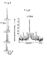
- FIG. 3 shows a spectrum of an isolated laser which is good by the choice of the operating point, that is to say both without a coupled optical waveguide and without a reflector.
- the operating point that is to say both without a coupled optical waveguide and without a reflector.
- FIG. 5 shows the spectrum of a laser with external stabilization by a reflector, incidentally in a logarithmic representation. Everything that appears there next to the one pronounced spectral line is below 1% in relation to this! In comparison to the spectrum according to FIG. 3, an improvement of about a factor of 10 has been achieved.
Landscapes
- Physics & Mathematics (AREA)
- General Physics & Mathematics (AREA)
- Optics & Photonics (AREA)
- Condensed Matter Physics & Semiconductors (AREA)
- Electromagnetism (AREA)
- Lasers (AREA)
- Semiconductor Lasers (AREA)
- Optical Couplings Of Light Guides (AREA)
Applications Claiming Priority (2)
| Application Number | Priority Date | Filing Date | Title |
|---|---|---|---|
| DE3330434 | 1983-08-19 | ||
| DE3330434A DE3330434A1 (de) | 1983-08-19 | 1983-08-19 | Stabilisationseinrichtung fuer einen halbleiter-laser |
Publications (2)
| Publication Number | Publication Date |
|---|---|
| EP0140820A2 true EP0140820A2 (fr) | 1985-05-08 |
| EP0140820A3 EP0140820A3 (fr) | 1986-04-16 |
Family
ID=6207256
Family Applications (1)
| Application Number | Title | Priority Date | Filing Date |
|---|---|---|---|
| EP84730088A Withdrawn EP0140820A3 (fr) | 1983-08-19 | 1984-08-17 | Dispositif de stabilisation pour un laser à semi-conducteur |
Country Status (3)
| Country | Link |
|---|---|
| EP (1) | EP0140820A3 (fr) |
| JP (1) | JPS6059794A (fr) |
| DE (1) | DE3330434A1 (fr) |
Cited By (4)
| Publication number | Priority date | Publication date | Assignee | Title |
|---|---|---|---|---|
| EP0308603A1 (fr) * | 1987-09-25 | 1989-03-29 | Siemens Aktiengesellschaft | Emetteur de laser dynamique monomode |
| DE3917388C1 (fr) * | 1989-05-29 | 1990-11-29 | Rainer 8000 Muenchen De Thiessen | |
| US5097476A (en) * | 1989-05-29 | 1992-03-17 | Polytec Gmbh & Co. | Laser sensor with external resonance cavity |
| EP0751415A3 (fr) * | 1995-06-28 | 1997-04-02 | Hewlett Packard Co | Commutateur mécanique à fibre-optique |
Families Citing this family (3)
| Publication number | Priority date | Publication date | Assignee | Title |
|---|---|---|---|---|
| US4761788A (en) * | 1985-10-28 | 1988-08-02 | American Telephone And Telegraph Company | Stripline mount for semiconductor lasers |
| US4902093A (en) * | 1988-07-22 | 1990-02-20 | Amp Incorporated | Laser diode to fiber reflective coupling |
| JP2555737B2 (ja) * | 1988-09-01 | 1996-11-20 | 旭硝子株式会社 | 自動車用窓ガラス |
Family Cites Families (1)
| Publication number | Priority date | Publication date | Assignee | Title |
|---|---|---|---|---|
| DE2222668A1 (de) * | 1972-05-09 | 1973-11-22 | Deutsche Bundespost | Justiervorrichtung fuer laserspiegel |
-
1983
- 1983-08-19 DE DE3330434A patent/DE3330434A1/de not_active Withdrawn
-
1984
- 1984-08-17 EP EP84730088A patent/EP0140820A3/fr not_active Withdrawn
- 1984-08-20 JP JP59171687A patent/JPS6059794A/ja active Pending
Cited By (5)
| Publication number | Priority date | Publication date | Assignee | Title |
|---|---|---|---|---|
| EP0308603A1 (fr) * | 1987-09-25 | 1989-03-29 | Siemens Aktiengesellschaft | Emetteur de laser dynamique monomode |
| DE3917388C1 (fr) * | 1989-05-29 | 1990-11-29 | Rainer 8000 Muenchen De Thiessen | |
| US5097476A (en) * | 1989-05-29 | 1992-03-17 | Polytec Gmbh & Co. | Laser sensor with external resonance cavity |
| EP0751415A3 (fr) * | 1995-06-28 | 1997-04-02 | Hewlett Packard Co | Commutateur mécanique à fibre-optique |
| US5699463A (en) * | 1995-06-28 | 1997-12-16 | Hewlett-Packard Company | Mechanical fiber optic switch |
Also Published As
| Publication number | Publication date |
|---|---|
| EP0140820A3 (fr) | 1986-04-16 |
| DE3330434A1 (de) | 1985-03-07 |
| JPS6059794A (ja) | 1985-04-06 |
Similar Documents
| Publication | Publication Date | Title |
|---|---|---|
| DE60036828T2 (de) | Laser mit automatisierter Steuerung der Strahlqualität | |
| DE68920765T2 (de) | Zusammenbau von elektrooptischen Halbleiter-Bauelementen. | |
| DE69736133T2 (de) | Direktes hochleistungslaserdiodensystem mit hoher effizienz und zugehörende verfahren | |
| DE69105952T3 (de) | Festkörper-Laserdioden-Lichtquelle | |
| DE69731148T2 (de) | Festkörperlaserverstärker | |
| DE3704338C2 (de) | Einrichtung zur Erzeugung verschiedener Laserwellenlängen aus demselben Lasermedium | |
| DE60101190T2 (de) | Laservorrichtung | |
| DE19703667A1 (de) | Ein optischer Modul und ein Temperatur-Steuerungsverfahren dafür | |
| DE102004045912B4 (de) | Verfahren und Vorrichtung zur Überlagerung von Strahlenbündeln | |
| DE3742553A1 (de) | Licht-, insbesondere laserstrahlrichtvorrichtung und -verfahren sowie laserarbeitsplatzsystem | |
| DE1879666U (de) | Laservorrichtung. | |
| WO1998056086A1 (fr) | Laser a solide comportant une ou plusieurs sources de lumiere de pompage | |
| EP0590393B1 (fr) | Module à laser semiconducteur | |
| EP0447768A1 (fr) | Module laser | |
| DE69018778T2 (de) | Optisch doppelgekuppelte Vorrichtung, insbesondere für optisches Faserübertragungssystem. | |
| EP2388145A1 (fr) | Unité de miroir de déviation et dispositif d'écriture au laser à l'aide d'une telle unité de déviation | |
| DE4490252B4 (de) | Leistungsgesteuertes fraktales Lasersystem | |
| DE68910142T2 (de) | Ausrichteverfahren, insbesondere für optische Bauteile. | |
| DE3330434A1 (de) | Stabilisationseinrichtung fuer einen halbleiter-laser | |
| DE19815306A1 (de) | Laserresonatorkonstruktion mit verbessertem Signal-Rausch-Wert (S/N) am Ausgang eines fasergekoppelten Einmodenlasers für mehrere Wellenlängen als Beleuchtungsquelle für ein Laser-Raster-Mikroskop | |
| DE2618310C3 (de) | Strahlerleuchte | |
| DE19548647C2 (de) | Durchstimmbare, justierstabile Halbleiterlaserlichtquelle sowie ein Verfahren zur optisch stabilen, weitgehend kontinuierlichen Durchstimmung von Halbleiterlasern | |
| DE60103675T2 (de) | Justierbare Halterung für ein optisches Element in einem Gaslaser | |
| DE69130056T2 (de) | Festkörper-Laservorrichtung und Bearbeitungsapparat, welcher dieselbe verwendet | |
| DE69502928T2 (de) | Verfahren zur regelung der schaltstrecke in einem reed-schalter |
Legal Events
| Date | Code | Title | Description |
|---|---|---|---|
| PUAI | Public reference made under article 153(3) epc to a published international application that has entered the european phase |
Free format text: ORIGINAL CODE: 0009012 |
|
| AK | Designated contracting states |
Designated state(s): AT BE CH DE FR GB IT LI LU NL SE |
|
| PUAL | Search report despatched |
Free format text: ORIGINAL CODE: 0009013 |
|
| AK | Designated contracting states |
Kind code of ref document: A3 Designated state(s): AT BE CH DE FR GB IT LI LU NL SE |
|
| STAA | Information on the status of an ep patent application or granted ep patent |
Free format text: STATUS: THE APPLICATION IS DEEMED TO BE WITHDRAWN |
|
| 18D | Application deemed to be withdrawn |
Effective date: 19861017 |
|
| RIN1 | Information on inventor provided before grant (corrected) |
Inventor name: KUELLER, LOTHAR, ING.-GRAD. Inventor name: WENKE, GERHARD, DIPL.-PHYS. Inventor name: GROSSKOPF, GERD, DR.-ING. Inventor name: PETERS, KLAUS, ING.-GRAD. |