EP0141023A1 - Tiroir plat - Google Patents
Tiroir plat Download PDFInfo
- Publication number
- EP0141023A1 EP0141023A1 EP84106975A EP84106975A EP0141023A1 EP 0141023 A1 EP0141023 A1 EP 0141023A1 EP 84106975 A EP84106975 A EP 84106975A EP 84106975 A EP84106975 A EP 84106975A EP 0141023 A1 EP0141023 A1 EP 0141023A1
- Authority
- EP
- European Patent Office
- Prior art keywords
- housing
- housing parts
- flange
- slide plate
- flat slide
- Prior art date
- Legal status (The legal status is an assumption and is not a legal conclusion. Google has not performed a legal analysis and makes no representation as to the accuracy of the status listed.)
- Granted
Links
Images


Classifications
-
- F—MECHANICAL ENGINEERING; LIGHTING; HEATING; WEAPONS; BLASTING
- F16—ENGINEERING ELEMENTS AND UNITS; GENERAL MEASURES FOR PRODUCING AND MAINTAINING EFFECTIVE FUNCTIONING OF MACHINES OR INSTALLATIONS; THERMAL INSULATION IN GENERAL
- F16K—VALVES; TAPS; COCKS; ACTUATING-FLOATS; DEVICES FOR VENTING OR AERATING
- F16K3/00—Gate valves or sliding valves, i.e. cut-off apparatus with closing members having a sliding movement along the seat for opening and closing
- F16K3/02—Gate valves or sliding valves, i.e. cut-off apparatus with closing members having a sliding movement along the seat for opening and closing with flat sealing faces; Packings therefor
- F16K3/0281—Guillotine or blade-type valves, e.g. no passage through the valve member
Definitions
- the invention relates to a flat slide valve whose housing enclosing the channel passage opening consists of two screwed-together housing parts, between which a guide pocket receiving the slide plate is formed. At the edge of the guide pocket there is a round groove that receives an all-round seal for the slide plate. The all-round seal is followed by two cross seals on both sides, transverse to the slide plate.
- the present invention has for its object to provide a flat slide valve with the same channel diameter and the same material thickness can be used in a wide pressure range and still consists of optimally light housing parts.
- the special design of the flat slide valve is intended to avoid the occurrence of leverage under the influence of the medium pressure, which leads to warping and bending of the housing parts and the slide plate.
- the statics of the flat slide g ereheatuses should be designed so that sudden increases in the medium pressure they can not influence.
- the number of types of the individual series (of the individual sewer pipe average) is to be considerably reduced, firstly by drastically increasing the pressure resistance range of the flat slide, whereby the same flat slide can be used for a wide range of working pressures, and secondly by the same Flat slide valve housing or the same housing parts can accommodate slide plates of different thicknesses.
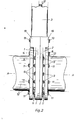
- the housing part 1 is composed of two housing parts 1, 2 and a drive part 3 which can be placed on them.
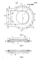
- the housing part 1 (FIGS. 4 and 5) has a trough-shaped recess 4 which, together with the housing part 2, forms a guide pocket 4 by the housing part 2 resting smoothly on the housing part 1.
- a circular duct opening 5 is common to both housing parts 1, 2.
- Figure 4 shows the housing part 1 with the guide pocket 4 in a plan view. Except for the guide pocket 4, the housing part 2 is mirror-identical to the housing part 1.
- a box-shaped recess 6 for the transverse seal 7 is formed on each housing part 1, 2 transversely to the longitudinal axis.
- the flat slide valve housing 1, 2 is created by placing the housing parts 1, 2 on top of one another and screwing them together using screw holes 8 and housing screws 9.
- the housing parts 1, 2 rest on one another via an edge region 10 (FIG. 4) which extends concentrically around the channel passage opening.
- the edge region 10 is partially flange-like and the flange-like configuration is correspondingly tapered relative to the body of the respective housing part.
- the flange-like configuration extends symmetrically about the central axis A of the channel flow opening 5, specifically over an angle w of at least 250 ° open in the direction of the guide pocket base 4 (illustration in FIG. 1). If this angle restriction is observed, optimum pressure resistance is guaranteed; in principle it is possible to make the angle w even larger.
- Bores 8 for the housing screws 9 and for the connecting screws for flange-mounting the sewer pipes 12 are incorporated in the edge area. Outside the edge area 10 there are bores 13 for further housing screws 9 and threaded bores 14 for the flange mounting of the sewer pipes 12.
- the bores 8, 14 are arranged on an arc K, the center of which is in the central axis A.
- the trough-shaped recess of the housing part 1, together with the smooth surface of the housing part 2, forms the guide pocket 4 for the slide plate 15, which is fastened in the drive part 3 via a holder 16 to a guide rod 17.
- the guide rod can optionally be connected to an electric drive, to a hydraulic system or to a hand spindle; this drive is not part of the invention and is therefore not described further.
- each housing part 1, 2 has a reinforcement 18, 19 (FIGS. 5 and 6), in the middle of which the recesses 6 for the transverse seal 7 are arranged.
- the transverse seal 7 is connected to an all-round seal 20 of the slide plate 15, which is located in an all-round groove 21 of the guide pocket.
- the sewer pipes 12 are flanged, cf. Figure 2.
- the illustration in Fig. 2 shows perfectly that the joining together of the housing 1, 2 and the flanging of the sewer pipes 12 do not offer any chance of creating leverage.
- the flat slide valve housing is fully balanced. This is the reason for the surprising increase in compressive strength for experts with the same use of materials.
- the principle of the tapered edge regions 10 of the slide housing parts 1, 2, as shown in FIG. 2, enables screws to be retightened at any time without having to remove housing parts first. Many repairs can be done without shutting down operations.
- the taper also saves material and weight.
- a flat slide valve according to the invention has three times the pressure resistance as a conventional flat slide valve of the same type and the same material thickness brings another advantage: a flat slide valve according to the invention, the type and material thickness of which corresponds to a conventional flat slide valve with a pressure resistance of 3 bar, can be used safely for working pressures up to 10 bar, so that for working pressures up to 10 bar you only have to have a single flat slide valve in stock.
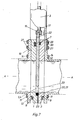
- FIG. 7 shows the section of a flat slide according to FIG. 2, but with a slide plate 22 that is 50% stronger.
- the slide plate 22 increases the pressure resistance of the flat slide compared to the flat slide FIGS. 2 and 3 by more than 100% (numerical example: 300 mm flat slide, 10 mm slide plate, pressure resistance 10 bar, 15 mm slide plate pressure resistance 23 bar).
- the housing parts 1, 2 have remained the same; only an intermediate part 23 is clamped between them, a sheet metal part with the contour of FIG. 4, but cut out in the circumference of the slide plate pocket 4 plus its all-round groove 21.
- the incisions for the transverse seal are also cut out insofar as they go beyond the circumference of the slide plate pocket 4, cf. Fig. 4. Since the thickness of the intermediate part 23 corresponds to the additional thickness of the thicker slide plate 22, the thicker slide plate 22 fits into the slide plate pocket 4 expanded by the intermediate part 23. Only the recess 6 on the housing part 1 has become too deep by the thickness of the intermediate part 23; here a compensating strip 24 made of steel or the like must be added to the transverse seal 7. The position of the slide plate wall that abuts the smooth housing part 2 remains the same for all slide plates, regardless of their different thickness.
- FIGS. 8 and 9 show an example of such a consolidation shown.
- the housing of the drive part 3 engages with two flanges 25, 26 over the housing parts 1, 2 and their reinforcements 18, 19 and are fastened to them by means of fastening screws.
- the flange 25 which extends over the housing part 1 has elongated holes 28 which absorb the displacement caused by the insertion of intermediate parts 23.
- the housing of the drive part 3 overlaps with a flange 29 over the housing part 2; the flange acts here as a reinforcement 18 by being screwed to the housing part 2 by a supplementary reinforcement 30.
- FIG. 10 shows a consequent use of the technical possibilities offered by the invention.
- unit screws 31 are used as connecting and connecting screws, which are screwed to one another on both sides of the housing parts 1, 2 and then protrude so far on both sides that they serve to fasten the sewer pipe flanges.
- the position of the screwed pipe flanges 12 and housing parts 1, 2 is indicated by dashed lines in FIG. 11.
- This embodiment makes it possible at any time, as in the case of the embodiment in FIG. 2, to detach a sewer pipe and carry out repairs without having to switch off the medium pressure in the system.
- the embodiment of Fig. 10 also brings an even more significant advantage: by halving the distances between the fixed points and the resultant halving of the lever arms, on which the medium pressure tries to deform the housing walls and the sewer pipe flanges, the static pressure resistance of the Flanged housing increased by at least 20%.
Landscapes
- Engineering & Computer Science (AREA)
- General Engineering & Computer Science (AREA)
- Mechanical Engineering (AREA)
- Details Of Valves (AREA)
- Sliding Valves (AREA)
- Magnetically Actuated Valves (AREA)
- Electrically Driven Valve-Operating Means (AREA)
- Superconductors And Manufacturing Methods Therefor (AREA)
- Valve Housings (AREA)
Priority Applications (1)
| Application Number | Priority Date | Filing Date | Title |
|---|---|---|---|
| AT84106975T ATE36744T1 (de) | 1983-08-31 | 1984-06-18 | Flachschieber. |
Applications Claiming Priority (2)
| Application Number | Priority Date | Filing Date | Title |
|---|---|---|---|
| DE3331350 | 1983-08-31 | ||
| DE19833331350 DE3331350A1 (de) | 1983-08-31 | 1983-08-31 | Flachschieber |
Publications (2)
| Publication Number | Publication Date |
|---|---|
| EP0141023A1 true EP0141023A1 (fr) | 1985-05-15 |
| EP0141023B1 EP0141023B1 (fr) | 1988-08-24 |
Family
ID=6207864
Family Applications (1)
| Application Number | Title | Priority Date | Filing Date |
|---|---|---|---|
| EP84106975A Expired EP0141023B1 (fr) | 1983-08-31 | 1984-06-18 | Tiroir plat |
Country Status (3)
| Country | Link |
|---|---|
| EP (1) | EP0141023B1 (fr) |
| AT (1) | ATE36744T1 (fr) |
| DE (2) | DE3331350A1 (fr) |
Cited By (4)
| Publication number | Priority date | Publication date | Assignee | Title |
|---|---|---|---|---|
| DE4037862A1 (de) * | 1990-11-28 | 1992-06-04 | Waldenmaier J E H | Absperrarmatur mit u-foermiger profildichtung |
| DE29610548U1 (de) * | 1996-06-15 | 1996-08-22 | WECO Armaturen GmbH, 51588 Nümbrecht | Schieberorgan mit Losflanschen |
| DE29610547U1 (de) * | 1996-06-15 | 1996-08-22 | WECO Armaturen GmbH, 51588 Nümbrecht | Schieberorgan in Blechkonstruktion |
| CN102359614A (zh) * | 2011-09-14 | 2012-02-22 | 成都海科机械设备制造有限公司 | 一种闸阀 |
Families Citing this family (2)
| Publication number | Priority date | Publication date | Assignee | Title |
|---|---|---|---|---|
| DE10112642A1 (de) * | 2001-03-16 | 2002-09-19 | Gerhard Geier Gmbh & Co Kg | Flachschieber |
| RU2205311C1 (ru) * | 2001-09-10 | 2003-05-27 | Григорьев Анатолий Анатольевич | Задвижка |
Citations (11)
| Publication number | Priority date | Publication date | Assignee | Title |
|---|---|---|---|---|
| GB671546A (en) * | 1949-12-05 | 1952-05-07 | Teddington Controls Ltd | Improvements in gate-type shut-off valves |
| GB681085A (en) * | 1951-07-18 | 1952-10-15 | Allan Grannenfelt | Improvements in or relating to sluice valves |
| US2663538A (en) * | 1948-03-29 | 1953-12-22 | Pelton Water Wheel Co | Spherical valve |
| US2891762A (en) * | 1954-06-10 | 1959-06-23 | Charles W Kellogg | Gate valve |
| FR1313971A (fr) * | 1961-11-23 | 1963-01-04 | Vanne utilisable en particulier pour l'industrie de la pâte à papier | |
| DE2411458A1 (de) * | 1974-03-11 | 1975-09-18 | Burbach Maschinenfab Erwin | Querdichtung fuer flachschieber |
| US4009727A (en) * | 1975-10-20 | 1977-03-01 | Thomas R. Bailey | Valve liner for a knife gate valve |
| DE2658809A1 (de) * | 1976-12-24 | 1978-06-29 | Sistag | Flachschieber |
| GB2101719A (en) * | 1979-01-02 | 1983-01-19 | George James Harris | Slide valve |
| EP0077681A2 (fr) * | 1981-10-16 | 1983-04-27 | D. Howse & Company Limited | Vis de fixation des os |
| DE3146994A1 (de) * | 1981-11-26 | 1983-06-01 | Dieter 7000 Stuttgart Schnell | Kunststoff-absperrschieber |
Family Cites Families (3)
| Publication number | Priority date | Publication date | Assignee | Title |
|---|---|---|---|---|
| DE7413451U (de) * | 1974-10-03 | Maschinenfabrik Sidler Stalder Ag | Querdichtung für Flachschieber | |
| CH314743A (de) * | 1953-04-18 | 1956-06-30 | Wey Joseph Dipl Masch Ing | Schieber |
| DE1169237B (de) * | 1953-10-13 | 1964-04-30 | Der Ludwig Von Roll Schen Eise | Flachschieber |
-
1983
- 1983-08-31 DE DE19833331350 patent/DE3331350A1/de not_active Withdrawn
-
1984
- 1984-06-18 EP EP84106975A patent/EP0141023B1/fr not_active Expired
- 1984-06-18 DE DE8484106975T patent/DE3473634D1/de not_active Expired
- 1984-06-18 AT AT84106975T patent/ATE36744T1/de not_active IP Right Cessation
Patent Citations (11)
| Publication number | Priority date | Publication date | Assignee | Title |
|---|---|---|---|---|
| US2663538A (en) * | 1948-03-29 | 1953-12-22 | Pelton Water Wheel Co | Spherical valve |
| GB671546A (en) * | 1949-12-05 | 1952-05-07 | Teddington Controls Ltd | Improvements in gate-type shut-off valves |
| GB681085A (en) * | 1951-07-18 | 1952-10-15 | Allan Grannenfelt | Improvements in or relating to sluice valves |
| US2891762A (en) * | 1954-06-10 | 1959-06-23 | Charles W Kellogg | Gate valve |
| FR1313971A (fr) * | 1961-11-23 | 1963-01-04 | Vanne utilisable en particulier pour l'industrie de la pâte à papier | |
| DE2411458A1 (de) * | 1974-03-11 | 1975-09-18 | Burbach Maschinenfab Erwin | Querdichtung fuer flachschieber |
| US4009727A (en) * | 1975-10-20 | 1977-03-01 | Thomas R. Bailey | Valve liner for a knife gate valve |
| DE2658809A1 (de) * | 1976-12-24 | 1978-06-29 | Sistag | Flachschieber |
| GB2101719A (en) * | 1979-01-02 | 1983-01-19 | George James Harris | Slide valve |
| EP0077681A2 (fr) * | 1981-10-16 | 1983-04-27 | D. Howse & Company Limited | Vis de fixation des os |
| DE3146994A1 (de) * | 1981-11-26 | 1983-06-01 | Dieter 7000 Stuttgart Schnell | Kunststoff-absperrschieber |
Cited By (6)
| Publication number | Priority date | Publication date | Assignee | Title |
|---|---|---|---|---|
| DE4037862A1 (de) * | 1990-11-28 | 1992-06-04 | Waldenmaier J E H | Absperrarmatur mit u-foermiger profildichtung |
| DE4037862C3 (de) * | 1990-11-28 | 1998-08-20 | Waldenmaier J E H | Absperrarmatur mit U-förmiger Profildichtung |
| DE29610548U1 (de) * | 1996-06-15 | 1996-08-22 | WECO Armaturen GmbH, 51588 Nümbrecht | Schieberorgan mit Losflanschen |
| DE29610547U1 (de) * | 1996-06-15 | 1996-08-22 | WECO Armaturen GmbH, 51588 Nümbrecht | Schieberorgan in Blechkonstruktion |
| CN102359614A (zh) * | 2011-09-14 | 2012-02-22 | 成都海科机械设备制造有限公司 | 一种闸阀 |
| CN102359614B (zh) * | 2011-09-14 | 2012-11-21 | 成都海科机械设备制造有限公司 | 一种闸阀 |
Also Published As
| Publication number | Publication date |
|---|---|
| ATE36744T1 (de) | 1988-09-15 |
| DE3473634D1 (en) | 1988-09-29 |
| EP0141023B1 (fr) | 1988-08-24 |
| DE3331350A1 (de) | 1985-03-14 |
Similar Documents
| Publication | Publication Date | Title |
|---|---|---|
| EP1870324A2 (fr) | Châssis à chaîne | |
| EP0141023B1 (fr) | Tiroir plat | |
| DE2365094C2 (de) | Spurkettenanordnung | |
| EP0034745A1 (fr) | Tiroir de commande pour pompes à liquides visqueux | |
| DE69102084T2 (de) | Schieberventil. | |
| EP0418718A1 (fr) | Manchonnage amortissant hydrauliquement | |
| EP0737610A2 (fr) | Direction à crémaillère hydraulique | |
| DE102019107646A1 (de) | Abwasser-Plattenschieber | |
| EP0302272A1 (fr) | Stockage de chaleur, en particulier stockage de chaleur latente | |
| DE2633443A1 (de) | Schieberventil | |
| DE4037863C2 (fr) | ||
| DE2357059A1 (de) | Plattenwaermeaustauscher und dergleichen | |
| DE8425285U1 (de) | Flachschieber | |
| DE9217697U1 (de) | Klappenventil | |
| DE102006009602A1 (de) | Traganordnung eines Behälters an einem tragenden Bauteil eines Lastkraftwagens | |
| EP1030986B1 (fr) | Dispositif pour realiser une etancheite | |
| DE102017104032B4 (de) | Membranventilgehäuse | |
| DE1450472B2 (de) | Absperrschiebergehaeuse bestehend aus einem gegossenen gehaeusemittelteil und daran befestigten gehaeuseseitenteilen | |
| DE102020109893A1 (de) | Gehäusedeckel | |
| DE724472C (de) | Absperrschieber | |
| DE102018208294A1 (de) | Kurbelwellenlager-Anordnung mit einem Zylinderkurbelgehäuse und einem Lagerdeckel | |
| DE8324982U1 (de) | Flachschieber | |
| DE1283626B (de) | Schiebergehaeuse | |
| DE7522584U (de) | Bauelementensatz für die Montage von Metallstrukturen mit Verbindungsanordnung | |
| DE2225556C3 (de) | Zweigeteilter, auf einen Mikrowellenhohlleiter aufsteckbarer Hohlleiterflansch |
Legal Events
| Date | Code | Title | Description |
|---|---|---|---|
| PUAI | Public reference made under article 153(3) epc to a published international application that has entered the european phase |
Free format text: ORIGINAL CODE: 0009012 |
|
| AK | Designated contracting states |
Designated state(s): AT BE CH DE FR GB IT LI LU NL SE |
|
| 17P | Request for examination filed |
Effective date: 19850522 |
|
| 17Q | First examination report despatched |
Effective date: 19860616 |
|
| GRAA | (expected) grant |
Free format text: ORIGINAL CODE: 0009210 |
|
| AK | Designated contracting states |
Kind code of ref document: B1 Designated state(s): AT BE CH DE FR GB IT LI LU NL SE |
|
| REF | Corresponds to: |
Ref document number: 36744 Country of ref document: AT Date of ref document: 19880915 Kind code of ref document: T |
|
| REF | Corresponds to: |
Ref document number: 3473634 Country of ref document: DE Date of ref document: 19880929 |
|
| ITF | It: translation for a ep patent filed | ||
| GBT | Gb: translation of ep patent filed (gb section 77(6)(a)/1977) | ||
| ET | Fr: translation filed | ||
| REG | Reference to a national code |
Ref country code: CH Ref legal event code: PUE Owner name: SISTAG, MASCHINENFABRIK SIDLER STALDER AG |
|
| RAP2 | Party data changed (patent owner data changed or rights of a patent transferred) |
Owner name: SISTAG, MASCHINENFABRIK SIDLER STALDER AG |
|
| REG | Reference to a national code |
Ref country code: FR Ref legal event code: TP |
|
| PLBE | No opposition filed within time limit |
Free format text: ORIGINAL CODE: 0009261 |
|
| STAA | Information on the status of an ep patent application or granted ep patent |
Free format text: STATUS: NO OPPOSITION FILED WITHIN TIME LIMIT |
|
| PG25 | Lapsed in a contracting state [announced via postgrant information from national office to epo] |
Ref country code: LU Free format text: LAPSE BECAUSE OF NON-PAYMENT OF DUE FEES Effective date: 19890630 |
|
| 26N | No opposition filed | ||
| NLS | Nl: assignments of ep-patents |
Owner name: SISTAG, MASCHINENFABRIK SIDLER STALDER AG TE ESCHE |
|
| REG | Reference to a national code |
Ref country code: GB Ref legal event code: 732 |
|
| BECH | Be: change of holder |
Free format text: 880824 *SISTAG MASCHINENFABRIK SILDER STADER A.G. |
|
| PGFP | Annual fee paid to national office [announced via postgrant information from national office to epo] |
Ref country code: SE Payment date: 19930429 Year of fee payment: 10 |
|
| PGFP | Annual fee paid to national office [announced via postgrant information from national office to epo] |
Ref country code: FR Payment date: 19930430 Year of fee payment: 10 |
|
| PGFP | Annual fee paid to national office [announced via postgrant information from national office to epo] |
Ref country code: AT Payment date: 19930525 Year of fee payment: 10 |
|
| PGFP | Annual fee paid to national office [announced via postgrant information from national office to epo] |
Ref country code: BE Payment date: 19930609 Year of fee payment: 10 |
|
| PGFP | Annual fee paid to national office [announced via postgrant information from national office to epo] |
Ref country code: GB Payment date: 19930617 Year of fee payment: 10 |
|
| ITTA | It: last paid annual fee | ||
| PGFP | Annual fee paid to national office [announced via postgrant information from national office to epo] |
Ref country code: NL Payment date: 19930630 Year of fee payment: 10 |
|
| PG25 | Lapsed in a contracting state [announced via postgrant information from national office to epo] |
Ref country code: GB Effective date: 19940618 Ref country code: AT Effective date: 19940618 |
|
| PG25 | Lapsed in a contracting state [announced via postgrant information from national office to epo] |
Ref country code: SE Effective date: 19940619 |
|
| PG25 | Lapsed in a contracting state [announced via postgrant information from national office to epo] |
Ref country code: BE Effective date: 19940630 |
|
| BERE | Be: lapsed |
Owner name: SISTAG MASCHINENFABRIK SILDER STADER A.G. Effective date: 19940630 |
|
| PG25 | Lapsed in a contracting state [announced via postgrant information from national office to epo] |
Ref country code: NL Effective date: 19950101 |
|
| EUG | Se: european patent has lapsed |
Ref document number: 84106975.0 Effective date: 19950110 |
|
| GBPC | Gb: european patent ceased through non-payment of renewal fee |
Effective date: 19940618 |
|
| NLV4 | Nl: lapsed or anulled due to non-payment of the annual fee | ||
| PG25 | Lapsed in a contracting state [announced via postgrant information from national office to epo] |
Ref country code: FR Effective date: 19950228 |
|
| EUG | Se: european patent has lapsed |
Ref document number: 84106975.0 |
|
| REG | Reference to a national code |
Ref country code: FR Ref legal event code: ST |
|
| REG | Reference to a national code |
Ref country code: CH Ref legal event code: PFA Free format text: SISTAG, MASCHINENFABRIK SIDLER STALDER AG TRANSFER- SISTAG ABSPERRTECHNIK Ref country code: CH Ref legal event code: NV Representative=s name: PATENTANWALT WILLI LUCHS |
|
| PGFP | Annual fee paid to national office [announced via postgrant information from national office to epo] |
Ref country code: CH Payment date: 19990624 Year of fee payment: 16 |
|
| PGFP | Annual fee paid to national office [announced via postgrant information from national office to epo] |
Ref country code: DE Payment date: 19990824 Year of fee payment: 16 |
|
| PG25 | Lapsed in a contracting state [announced via postgrant information from national office to epo] |
Ref country code: LI Free format text: LAPSE BECAUSE OF NON-PAYMENT OF DUE FEES Effective date: 20000630 Ref country code: CH Free format text: LAPSE BECAUSE OF NON-PAYMENT OF DUE FEES Effective date: 20000630 |
|
| REG | Reference to a national code |
Ref country code: CH Ref legal event code: PL |
|
| PG25 | Lapsed in a contracting state [announced via postgrant information from national office to epo] |
Ref country code: DE Free format text: LAPSE BECAUSE OF NON-PAYMENT OF DUE FEES Effective date: 20010403 |