EP0141082A2 - Tissu de filtre pour filtre rotatif à disques - Google Patents
Tissu de filtre pour filtre rotatif à disques Download PDFInfo
- Publication number
- EP0141082A2 EP0141082A2 EP84109501A EP84109501A EP0141082A2 EP 0141082 A2 EP0141082 A2 EP 0141082A2 EP 84109501 A EP84109501 A EP 84109501A EP 84109501 A EP84109501 A EP 84109501A EP 0141082 A2 EP0141082 A2 EP 0141082A2
- Authority
- EP
- European Patent Office
- Prior art keywords
- filter cloth
- filter
- cloth according
- stiffeners
- legs
- Prior art date
- Legal status (The legal status is an assumption and is not a legal conclusion. Google has not performed a legal analysis and makes no representation as to the accuracy of the status listed.)
- Withdrawn
Links
Images


Classifications
-
- B—PERFORMING OPERATIONS; TRANSPORTING
- B01—PHYSICAL OR CHEMICAL PROCESSES OR APPARATUS IN GENERAL
- B01D—SEPARATION
- B01D39/00—Filtering material for liquid or gaseous fluids
- B01D39/14—Other self-supporting filtering material ; Other filtering material
-
- B—PERFORMING OPERATIONS; TRANSPORTING
- B01—PHYSICAL OR CHEMICAL PROCESSES OR APPARATUS IN GENERAL
- B01D—SEPARATION
- B01D33/00—Filters with filtering elements which move during the filtering operation
- B01D33/15—Filters with filtering elements which move during the filtering operation with rotary plane filtering surfaces
- B01D33/21—Filters with filtering elements which move during the filtering operation with rotary plane filtering surfaces with hollow filtering discs transversely mounted on a hollow rotary shaft
- B01D33/23—Construction of discs or component sectors thereof
-
- B—PERFORMING OPERATIONS; TRANSPORTING
- B01—PHYSICAL OR CHEMICAL PROCESSES OR APPARATUS IN GENERAL
- B01D—SEPARATION
- B01D39/00—Filtering material for liquid or gaseous fluids
- B01D39/08—Filter cloth, i.e. woven, knitted or interlaced material
-
- B—PERFORMING OPERATIONS; TRANSPORTING
- B01—PHYSICAL OR CHEMICAL PROCESSES OR APPARATUS IN GENERAL
- B01D—SEPARATION
- B01D46/00—Filters or filtering processes specially modified for separating dispersed particles from gases or vapours
- B01D46/02—Particle separators, e.g. dust precipitators, having hollow filters made of flexible material
- B01D46/06—Particle separators, e.g. dust precipitators, having hollow filters made of flexible material with means keeping the working surfaces flat
-
- B—PERFORMING OPERATIONS; TRANSPORTING
- B01—PHYSICAL OR CHEMICAL PROCESSES OR APPARATUS IN GENERAL
- B01D—SEPARATION
- B01D2239/00—Aspects relating to filtering material for liquid or gaseous fluids
- B01D2239/06—Filter cloth, e.g. knitted, woven non-woven; self-supported material
- B01D2239/065—More than one layer present in the filtering material
- B01D2239/0654—Support layers
-
- B—PERFORMING OPERATIONS; TRANSPORTING
- B01—PHYSICAL OR CHEMICAL PROCESSES OR APPARATUS IN GENERAL
- B01D—SEPARATION
- B01D2239/00—Aspects relating to filtering material for liquid or gaseous fluids
- B01D2239/06—Filter cloth, e.g. knitted, woven non-woven; self-supported material
- B01D2239/065—More than one layer present in the filtering material
- B01D2239/0659—The layers being joined by needling
Definitions
- the invention relates to a filter cloth for a disc filter with in particular sector-shaped and stiffening filter cells.
- Another disadvantage of the heavily bulged filter cloth is that the air cannot escape quickly enough and the filter cloth thus passes the scraper when it is inflated and grazes there.
- Such a disc filter therefore has two perforated plates on which the filter cloth is clamped by means of clamping strips. These terminal strips can run radially and / or in the form of an arc of a circle and / or in the shape of a star or a plate. It is essential, however, that in this existing disc filter to fix the filter cloth, in addition to the perforated plates, clamping strips are required in order to rule out excessive bulges of the filter cloth. Retrofitting existing filter systems is not without problems, since perforated plates and terminal strips have to be adapted accordingly, so that the undesired strong bulges are safely excluded. It is therefore an object of the invention to provide a filter cloth in which strong bulges during the action of compressed air to remove the filter cake are excluded in a simple manner.
- stiffeners are included directly in the fabric of the filter cloth.
- the stiffeners made of metal or plastic or other rigid material are U-shaped brackets, the leg or end distance of which is adapted to the disc filter segment thickness.
- the brackets can have a flat profile or a round profile.
- clamps are fixed with their legs, for example, in a hem formed by the seam of two filter bag halves or in a hemstitch obtained by sewing a band-shaped piece of fabric onto the fabric of the filter cloth or in loops attached to the fabric of the filter cloth, making it possible in a simple manner to include the stiffening brackets in the fabric of the filter cloth: it is sufficient if the free ends or legs of the brackets are inserted into the hems or hemstitch or tabs, whereby the disc filter segment thickness is determined at the same time.
- the ends of the limbs of the clips can be fixed with tabs, which results in a particularly secure connection between the tissue and clips. It is also possible to fix the ends of the limbs of the clips by means of a further clip or clip attached to the outside of the filter cloth.
- the stiffeners can run radially and / or in a circular arc. It is only important that the stiffeners are guided in such a way that excessive bulges of the filter cloth during the action of compressed air are avoided.
- the stiffeners can also be firmly incorporated into the fabric, i.e. the stiffeners in the form of flat profiles or round profiles can be sewn firmly into, for example, hemstitching of the fabric.
- a filter cell it is also possible for a filter cell to have a plurality of stiffeners, which is particularly true if this filter cell has a relatively large surface area, so that larger bulges are to be feared.
- stiffeners or brackets are selected depending on the intended use of the disc filter. If particularly aggressive materials are treated with the disc filter, the stiffeners are suitably made of stainless steel or a suitable plastic.
- the filter cloth according to the invention can also be used together with a perforated plate, on the surface of which it is placed. This will be the case in particular if the disc filter has a relatively large diameter. Such a perforated plate is not required for smaller diameters.
- the stiffeners should also be concave in accordance with the perforated plate so that the filter cloth is adapted to the concave surface of the perforated plate.
- the invention enables a filter cloth for a disc filter, in which the stiffeners are included directly in the fabric of the filter cloth, so that no special measures have to be provided, which consist in an interaction of K clamping strips and a perforated plate only for fixing the filter cloth.
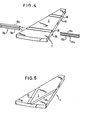
- FIGS. 1 to 5 each show a sector-shaped filter cell of the filter cloth.
- a sector-shaped filter cell 1 which consists of a filter cloth 2, which forms two filter bag halves.
- a clip 7 made of metal or plastic or another stiff material with a flat profile can be inserted.
- This clip 7 has a U-shaped shape and has legs 8.9, which are each fixed in the hemstones 5,6.
- the distance d between the legs 8.9 of the bracket 7 is exactly adapted to the disc filter segment thickness d. If the legs 8, 9 of the clamp 7 are pushed into the hemstones 5, 6 of the filter cell 1, then this filter cell 1 is stiffened in its segment thickness by the clamp 7.
- two tabs 10, 11 can be provided at the head end of the filter cell 1, for example, by means of which the ends of the legs 8, 9 of the clamp 7 are fixed particularly securely.
- the tabs 10 and 11 are attached to the filter segment made of plastic or metal or another corresponding material, so that the leg ends of the clips get an additional hold. It is also possible to attach an additional clip or clip to the outside of the fabric in such a way that the ends of the legs 8, 9 of the clip 7 are particularly well fixed.
- Fig. 2 shows a further embodiment of the invention, in which the leg 3 of the clamp 7 is fixed by loops 12 which are sewn onto the surface of the filter cloth 2.
- loops 12 are sewn onto the surface of the filter cloth 2.
- FIG. 3 shows a filter cell 1 with a particularly large filter segment area.
- this filter segment surface is divided by several hollow seams 5, 6, 15, 16 and 25, 26.
- loops corresponding to the embodiment of FIG. 2 can of course also be provided.
- FIG. 4 shows an embodiment of the invention in which hemsticks 35, 36 and 45, 46 for receiving stiffeners run in a circular arc and not radially as in the other embodiments. If necessary, such circular-arc-shaped stiffeners can be provided in addition to radial stiffeners.
- the U-legs 18a and 18b of the U-shaped fork 17a are inserted into the hemstitch 35 and 36 from one side and the U-legs 19a and 19b of the U-shaped fork 17b from the other side.
- the free ends of the two U-legs 19a and 19b arrive at the locations marked by arrows in the end openings of the U-legs 18a and 18b, which are designed as hollow profiles. With sufficient rigidity of the brackets, any additional mounting is unnecessary in this embodiment, since the two Fix each other in brackets.
- FIG. 5 shows a further exemplary embodiment of the invention, in which hemstuffs 55 and 65 practically run from a common point on the circumference of the filter cell 1 in a V-shape towards the center of the pane.
- This embodiment is particularly advantageous for very wide filter cells. Namely, it is a particularly large area of the filter cell through the embodiment illustrated in Figure 5 of the Principalsfnrm Erfindun sgenenstandes g such divided dministerkeine large bulge can occur more.
Landscapes
- Chemical & Material Sciences (AREA)
- Chemical Kinetics & Catalysis (AREA)
- Engineering & Computer Science (AREA)
- Textile Engineering (AREA)
- Filtering Of Dispersed Particles In Gases (AREA)
- Treatment Of Fiber Materials (AREA)
Applications Claiming Priority (2)
| Application Number | Priority Date | Filing Date | Title |
|---|---|---|---|
| DE3329117A DE3329117A1 (de) | 1983-08-11 | 1983-08-11 | Filtertuch fuer scheibenfilter |
| DE3329117 | 1983-08-11 |
Publications (2)
| Publication Number | Publication Date |
|---|---|
| EP0141082A2 true EP0141082A2 (fr) | 1985-05-15 |
| EP0141082A3 EP0141082A3 (fr) | 1987-08-19 |
Family
ID=6206371
Family Applications (1)
| Application Number | Title | Priority Date | Filing Date |
|---|---|---|---|
| EP84109501A Withdrawn EP0141082A3 (fr) | 1983-08-11 | 1984-08-09 | Tissu de filtre pour filtre rotatif à disques |
Country Status (4)
| Country | Link |
|---|---|
| US (1) | US4578192A (fr) |
| EP (1) | EP0141082A3 (fr) |
| DE (1) | DE3329117A1 (fr) |
| FI (1) | FI843164A7 (fr) |
Families Citing this family (7)
| Publication number | Priority date | Publication date | Assignee | Title |
|---|---|---|---|---|
| SE9001807L (sv) * | 1990-05-18 | 1991-11-11 | Celleco Hedemora Ab | Anordning vid silduk foer roterande filter |
| ATE249869T1 (de) * | 2001-02-20 | 2003-10-15 | Sefar Ag | Filtertuch |
| US8252181B2 (en) * | 2007-07-19 | 2012-08-28 | Gerald Pitre | Horizontal ore filter with replaceable filter elements |
| DK2203231T3 (da) * | 2007-09-26 | 2011-12-05 | Gaudfrin | Skiveformet filtreringsindretning |
| US9669338B2 (en) * | 2015-03-11 | 2017-06-06 | GL & V Luxembourg Sàrl | Disc filter and a method of constructing a disc filter sector |
| US11000791B2 (en) * | 2019-03-06 | 2021-05-11 | Veolia Water Solutions & Technologies Support | Rotary disc filter having backwash guides |
| US12220657B2 (en) * | 2021-04-30 | 2025-02-11 | Pall Corporation | Filter disk segments |
Family Cites Families (13)
| Publication number | Priority date | Publication date | Assignee | Title |
|---|---|---|---|---|
| US1240385A (en) * | 1914-05-09 | 1917-09-18 | Ernest J Sweetland | Filter. |
| US1878384A (en) * | 1929-04-18 | 1932-09-20 | Hoover Co | Suction cleaner |
| US1894884A (en) * | 1930-05-07 | 1933-01-17 | Warren E Page | Vacuum cleaner bag attachment |
| US2338549A (en) * | 1941-08-01 | 1944-01-04 | Us Rubber Co | Filter bag |
| FR1059010A (fr) * | 1951-04-05 | 1954-03-22 | Tecalemit | Filtres à fluides |
| GB764500A (en) * | 1953-07-16 | 1956-12-28 | Peterson Filters & Eng | Coutinuous filter and method of operation thereof |
| NL238623A (fr) * | 1958-04-29 | |||
| US3165473A (en) * | 1960-10-24 | 1965-01-12 | Pall Corp | Corrugated filter unit |
| US3807146A (en) * | 1967-02-21 | 1974-04-30 | H Witkowski | Mold for making a filter |
| DE1930046A1 (de) * | 1969-06-13 | 1971-02-11 | Ardie Werk Gmbh | Verfahren und Vorrichtung zum Schalten von mehrstufigen Zahnradwechselgetrieben |
| DE2144806A1 (de) * | 1971-09-08 | 1973-03-15 | Joseph Dipl Ing Brokhage | Filterscheibe |
| GB1544822A (en) * | 1976-03-26 | 1979-04-25 | Process Scient Innovations | Filter elements for gas or liquid and methods of making such elements |
| US4362622A (en) * | 1981-03-30 | 1982-12-07 | Ingersoll-Rand Company | Filter |
-
1983
- 1983-08-11 DE DE3329117A patent/DE3329117A1/de not_active Withdrawn
-
1984
- 1984-08-09 EP EP84109501A patent/EP0141082A3/fr not_active Withdrawn
- 1984-08-10 US US06/639,404 patent/US4578192A/en not_active Expired - Fee Related
- 1984-08-10 FI FI843164A patent/FI843164A7/fi not_active Application Discontinuation
Also Published As
| Publication number | Publication date |
|---|---|
| FI843164A0 (fi) | 1984-08-10 |
| DE3329117A1 (de) | 1985-02-28 |
| EP0141082A3 (fr) | 1987-08-19 |
| FI843164L (fi) | 1985-02-12 |
| FI843164A7 (fi) | 1985-02-12 |
| US4578192A (en) | 1986-03-25 |
Similar Documents
| Publication | Publication Date | Title |
|---|---|---|
| DE69835963T2 (de) | Drehscheibenfilter | |
| EP0982433B1 (fr) | Tambour cylindrique pour un appareil de tamisage sous pression comportant un tamis cylindrique remplaçable | |
| DE69403952T2 (de) | Vorrichtung zur filtration von flüssigkeiten | |
| DE2818340C2 (de) | Flüssigkeits-Feststoff-Filter, insbesondere Restvolumen-Anschwemmfilter | |
| DE2218461B2 (de) | Vorrichtung zum Befestigen der Filterschläuche von Schlauchfiltern | |
| DE2551866C3 (de) | Einrichtung zum Einbau von Schlauchfilterbaugruppen | |
| DE1948774C3 (de) | Filtereinsatz für Anschwemmfiltration | |
| DE3117625A1 (de) | Wegwerf-luftfilter | |
| DE2249603A1 (de) | Filterelement | |
| DE2351407A1 (de) | Klemmvorrichtung fuer ein druckgefaess | |
| EP0141082A2 (fr) | Tissu de filtre pour filtre rotatif à disques | |
| DE68927017T2 (de) | Gegenstromfilterelement | |
| DE3331770A1 (de) | Filtereinheit sowie loesbarer filter zur verbindung mit einem weiteren filter | |
| EP4272852B1 (fr) | Module filtrant pour un filtre à disque rotatif et filtre à disque rotatif | |
| WO2015124306A1 (fr) | Dispositif de filtration d'une matière plastique en fusion | |
| DE3537440A1 (de) | Vorrichtung zum kontinuierlichen filtern eines gases | |
| DE4432004C2 (de) | Vorrichtung zur Befestigung von Filtermedien auf Filterelementen | |
| EP0699465A2 (fr) | Filtre à air | |
| DE4135359C1 (fr) | ||
| DE202019004268U1 (de) | Filtriervorrichtung für Kunststoffschmelzen | |
| DE2322452B2 (de) | Filterpressenelement | |
| EP0352404B1 (fr) | Elément filtrant | |
| EP0442891A1 (fr) | Procede et dispositif pour retourner la membrane d'un filtre-presse pour suspensions. | |
| DE829244C (de) | Filtriervorrichtung fuer Milch und aehnliche Fluessigkeiten | |
| DE3141519C2 (de) | Anschwemmfilter für die Feinstfiltration von Flüssigkeiten |
Legal Events
| Date | Code | Title | Description |
|---|---|---|---|
| PUAI | Public reference made under article 153(3) epc to a published international application that has entered the european phase |
Free format text: ORIGINAL CODE: 0009012 |
|
| AK | Designated contracting states |
Designated state(s): CH FR GB IT LI SE |
|
| 17P | Request for examination filed |
Effective date: 19851030 |
|
| PUAL | Search report despatched |
Free format text: ORIGINAL CODE: 0009013 |
|
| AK | Designated contracting states |
Kind code of ref document: A3 Designated state(s): CH FR GB IT LI SE |
|
| 17Q | First examination report despatched |
Effective date: 19880204 |
|
| STAA | Information on the status of an ep patent application or granted ep patent |
Free format text: STATUS: THE APPLICATION IS DEEMED TO BE WITHDRAWN |
|
| 18D | Application deemed to be withdrawn |
Effective date: 19880615 |
|
| RIN1 | Information on inventor provided before grant (corrected) |
Inventor name: MUELLER, HANS-RUDOLF |