EP0141142A2 - Electrode à diffusion gazeuse à couche de revêtement hydrophile et procédé de fabrication - Google Patents
Electrode à diffusion gazeuse à couche de revêtement hydrophile et procédé de fabrication Download PDFInfo
- Publication number
- EP0141142A2 EP0141142A2 EP84110443A EP84110443A EP0141142A2 EP 0141142 A2 EP0141142 A2 EP 0141142A2 EP 84110443 A EP84110443 A EP 84110443A EP 84110443 A EP84110443 A EP 84110443A EP 0141142 A2 EP0141142 A2 EP 0141142A2
- Authority
- EP
- European Patent Office
- Prior art keywords
- oxide
- hydrophobic
- gas diffusion
- diffusion electrode
- layer
- Prior art date
- Legal status (The legal status is an assumption and is not a legal conclusion. Google has not performed a legal analysis and makes no representation as to the accuracy of the status listed.)
- Granted
Links
Images
Classifications
-
- H—ELECTRICITY
- H01—ELECTRIC ELEMENTS
- H01M—PROCESSES OR MEANS, e.g. BATTERIES, FOR THE DIRECT CONVERSION OF CHEMICAL ENERGY INTO ELECTRICAL ENERGY
- H01M4/00—Electrodes
- H01M4/86—Inert electrodes with catalytic activity, e.g. for fuel cells
-
- C—CHEMISTRY; METALLURGY
- C25—ELECTROLYTIC OR ELECTROPHORETIC PROCESSES; APPARATUS THEREFOR
- C25B—ELECTROLYTIC OR ELECTROPHORETIC PROCESSES FOR THE PRODUCTION OF COMPOUNDS OR NON-METALS; APPARATUS THEREFOR
- C25B11/00—Electrodes; Manufacture thereof not otherwise provided for
- C25B11/02—Electrodes; Manufacture thereof not otherwise provided for characterised by shape or form
- C25B11/03—Electrodes; Manufacture thereof not otherwise provided for characterised by shape or form perforated or foraminous
- C25B11/031—Porous electrodes
- C25B11/032—Gas diffusion electrodes
-
- Y—GENERAL TAGGING OF NEW TECHNOLOGICAL DEVELOPMENTS; GENERAL TAGGING OF CROSS-SECTIONAL TECHNOLOGIES SPANNING OVER SEVERAL SECTIONS OF THE IPC; TECHNICAL SUBJECTS COVERED BY FORMER USPC CROSS-REFERENCE ART COLLECTIONS [XRACs] AND DIGESTS
- Y02—TECHNOLOGIES OR APPLICATIONS FOR MITIGATION OR ADAPTATION AGAINST CLIMATE CHANGE
- Y02E—REDUCTION OF GREENHOUSE GAS [GHG] EMISSIONS, RELATED TO ENERGY GENERATION, TRANSMISSION OR DISTRIBUTION
- Y02E60/00—Enabling technologies; Technologies with a potential or indirect contribution to GHG emissions mitigation
- Y02E60/30—Hydrogen technology
- Y02E60/50—Fuel cells
Definitions
- the present invention relates to a gas diffusion cathode for oxygen reduction in alkaline solution, which is provided on one side with a hydrophilic cover layer.
- Aqueous sodium chloride electrolysis is an important process for the production of the heavy chemicals chlorine and sodium hydroxide.
- a modern variant is carried out in a membrane cell.
- the electrolysis cell consists of an anode compartment with an anode and a cathode compartment with a cathode, and a cation exchange membrane that separates the two electrolysis compartments. If a saturated sodium chloride solution is fed into the anode compartment, the chloride ions at the anode are discharged to elemental chlorine under the influence of the electric current. At the same time, water is broken down at the cathode to form elemental hydrogen and hydroxide ions. Sodium ions migrate from the anode space through the membrane into the cathode space to approximately the same extent as hydroxide ions are generated.
- the underlying chemical reaction corresponds to the following equation:
- the hydrogen produced is an undesirable by-product.
- the potential for hydrogen separation according to the equation is -0.83 V based on the standard hydrogen electrode. Due to the polarization of the cathode with oxygen, one can be made at the negative pole of the electrolytic cell. Force response that corresponds to the following equation:
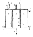
- an electrochemical cell for the electrolysis of aqueous sodium chloride solutions is shown schematically, which is equipped with a gas diffusion electrode.
- the cell is divided into an anode compartment (1), a cathode compartment (2) and a gas compartment (3).
- Saturated sodium chloride brine is pumped into the anode compartment (1) via a feed line (4).
- Chloride ions are discharged to elemental chlorine at the anode (5).
- Dimensionally stable anodes made of titanium are preferably used, which are equipped with an activation in order to keep the chlorine overvoltage low.
- the chlorine formed and the depleted brine leave the anode compartment (1) via line (6).
- the reactant water is fed via the feed line (9) to the cell in the form of deionized water or dilute sodium hydroxide solution.
- Sodium hydroxide solution is formed in the cathode compartment (2) and leaves the cell via the opening (10).
- the cathode compartment (2) and the gas compartment (3) are separated from one another by the gas diffusion electrode (8), which serves as the cathode.
- An oxygen-containing gas (pure oxygen, CO 2 -free air or oxygen-enriched and / or humidified air) is introduced into the gas space (3) via pipe (11). The gas penetrates the diffusion electrode, reducing oxygen. The remaining gas finally leaves the cell, generally depleted of oxygen, via line (12).
- the electrode (8) represents a porous body that allows the access of the reactants water and oxygen. It mainly consists of an electrochemically active material that catalyzes oxygen reduction.
- the electrode is often manufactured in a supported form, i.e. a mesh-shaped current collector made of metal is incorporated into the electrocatalyst layer or supports it from the outside.
- Porous metals such as platinum black, silver black or nickel black, other substances such as phthalocyanines, mixed oxides of the spinel or perovskite type and activated carbon, which can be activated with a catalyst suitable for oxygen reduction, serve as the electrocatalyst.
- a hydrophobic material preferably polytetrafluoroethylene (PTFE)
- PTFE polytetrafluoroethylene
- Hydrophobic electrodes containing PTFE are described, for example, in U.S. Patents 43 50 608, 43 39 325, 4 179 350, 3 977 901 and 3 537 906.
- the required cell voltage of such a cell is composed of the electrode potentials, the overvoltages on the two electrodes, the membrane resistance and the voltage drop within the electrolyte.
- the overvoltages on the electrodes can be influenced by selecting a suitable electrochemically active electrode material.
- the membrane resistance is constant and given by the choice of the cation exchange membrane.
- the electrolyte resistance can be reduced by bringing the two electrodes as close together as possible. Since the cell has to be supplied with water, the distance between cathode and anode cannot be less than a certain amount. In practice, however, the distance between the membrane and the gas diffusion electrode will be kept as small as possible. Distances between 0.5 and 3 mm, in particular between 0.5 and 1 mm, have proven effective.
- the object was therefore to prevent the gas bubbles from adhering to the oxygen diffusion cathode and to ensure that any gas bubbles (air or D 2 ) formed are discharged from the catholyte gap.
- the present invention solves this problem by using a gas diffusion electrode for oxygen reduction which contains a hydrophobic electrocatalyst layer and which is characterized in that one side of the electrocatalyst layer is covered with a hydrophilic layer consisting of at least one transition metal or an oxide or mixed oxide of transition metals .
- the electrode according to the invention preferably has the shape of a flat surface. It is particularly suitable for oxygen reduction in an alkaline environment, i.e. under the conditions of aqueous chlor-alkali electrolysis. Gas bubbles are prevented from adhering to the hydrophilically coated side. Surprisingly, such coated electrodes have a higher electrochemical activity and thus a lower overvoltage than uncoated electrodes.
- the transition metals which serve in the form of the metals or oxides of the coating, are selected in particular from the group consisting of titanium, chromium, manganese, iron, cobalt, nickel, copper, zinc, silver, ruthenium, rhodium, palladium, osmium, iridium and Platinum. Coating with the electrocatalytically active metals silver and platinum is advantageous, but especially with nickel. To apply nickel with a particularly large surface area, one can proceed by first coating with a nickel-aluminum alloy and later removing the aluminum portion of the alloy by treatment with aqueous alkali.
- the hydrophobic electrocatalyst layer is preferably produced on the basis of metallic silver.
- the electrode (8) according to the invention can be seen schematically in cross section in the figure.
- An embodiment is shown in which the current is supplied by a network-shaped current collector (13).
- This is preferably a metal network made of nickel or silver-plated nickel which, in addition to the current supply, also takes over the current distribution within the catalyst layer (14).
- the hydrophilic cover layer (15) is applied to (14). It prevents gas bubbles from sticking to the electrode surface and facilitates the supply of water to the actual reaction zone and the removal of hydroxyl ions formed.
- the reaction takes place at the three-phase water-oxygen electrocatalyst, which should form within (14).
- hydrophilic coating material which is as finely divided as possible, in particular material with a particle size of less than 0.063 mm. Very fine fractions can be obtained by grinding, chopping in a cross beater mill or mortar, and subsequent sieving.
- the thickness of the coating with hydrophilic material should be between 1 and 200, in particular 2 and 50, preferably 2.5 and 20 mg / em 2.
- the gas diffusion electrode according to the invention can be produced by first producing a hydrophobic catalyst layer (usually in the form of a flat surface) from a powdery mixture which contains an electrocatalyst and a hydrophobic polymer. At least one transition metal or an oxide or mixed oxide of transition metals is applied to one side of this layer in finely divided form and connected to the hydrophobic electrocatalyst layer by applying pressure.
- the electrophilic layer for example, a suspension of a specified hydrophilic material in water or in an organic solvent (such as alcohol, methylene chloride or petroleum ether) on the hydrophobic electro Apply the catalyst layer and allow the liquid phase to evaporate there.
- the specified suspension can also be filtered, the hydrophobic electrocatalyst layer being the filter, or the hydrophilic material in powder form can be applied uniformly to the electrocatalyst layer, e.g. by means of a sieve. Subsequent pressing or rolling (exposure to pressure) intimately connects the coating material to the raw electrode.
- the use of heat is advantageous here because the hydrophobic portion of the electrocatalyst layer becomes thermoplastic at least at high temperatures.
- hydrophobic electrocatalyst layers produced in another way can also be coated according to the invention.
- An electrode was produced as in Example 1, except that a manganese dioxide was used instead of zinc oxide, the largest particles of which pass through a sieve with a mesh size of 0.06 mm.
- the electrode coverage was approximately 16 mg / cm 2 of MnO 2 .
- the measured potentials vs GKE are shown in Table 1.
- Example 1 was repeated, but silver oxide was used as the coating material (24 mg / cm 2 ).
- the measured potentials vs GKE can be found in Table 1.
- An electrode was produced analogously to Example 1, but using iron powder with a grain size of 0.06 mm as the coating material.
- the coverage of the electrode with iron was about 28 mg / cm 2 .
- the measured potentials vs GKE are shown in Table 1.
- An electrode was produced in the same way as in Example 1, except that nickel powder with a grain size of 0.06 mm was used as the coating material.
- the coverage of the electrode with nickel was about 36 mg / cm 2 .
- the measured potentials vs GKE are listed in Table 1.
- An electrode was produced as in Example 1, except that silver powder was used for the coating instead of zinc oxide.
- the coverage of this electrode with silver was about 18 mg / cm2.
- the measured potentials vs GKE are listed in Table 1.
- aqueous polytetrafluoroethylene dispersion (trade name Hostaflon @ TF 5033-40%) are added 280 ml of water and 45 ml of a 35% formaldehyde solution and the mixture is cooled to 0 to 10 ° C.
- a solution of 30.3 g of silver nitrate and 3.2 g of mercury (II) nitrate in 450 ml of water and 310 ml of a 10% potassium hydroxide solution are added dropwise over the course of about 3.5 hours.
- the reaction mixture is mixed vigorously; the reaction temperature should not exceed 15 ° C.
- the potassium hydroxide solution must be dosed so that the pH does not rise above 10; the pH should not fall below 7.5. After the reaction has ended, the precipitate formed is allowed to settle, the supernatant mother liquor is decanted off and the remaining solid is washed first with water and then with petroleum ether. After drying at 110 ° C, the yield of catalyst material is 24.8 g.
- the silver content of the material produced in this way is approximately 77% by weight, the mercury content 8% by weight.
- the still moist filter cake was pressed at a pressure of 20 bar into a silver-plated nickel mesh with a mesh size of 0.25 mm and a wire thickness of 0.16 mm. After drying for one hour at 110 ° C., the raw electrode was dusted with 170 mg of a nickel-aluminum alloy, each consisting of 50% by weight of the two metals. The particle size was less than 0.063 mm. The dusted electrode was then pressed at a pressure of 60 bar and sintered at 250 ° C. for 15 minutes. The sintered electrode was placed in a 10% sodium hydroxide solution for 15 hours in order to dissolve out the aluminum and the sodium chloride serving as pore former.
- the coating on the electrode was about 65 mg / cm 2 of catalyst and about 6 mg / cm 2 of Raney nickel coating.
- the measured potentials against a saturated calom electrode are listed in Table 1.
- An analog electrode with an active area of 40 cm 2 was operated in an electrolysis cell for 20 weeks, producing 8.25N sodium hydroxide solution.
- the cell voltage was 2.14 V.
- the cathode gap was only 1 mm wide, no adhesion of gas bubbles between the electrode and the cation exchange membrane was observed.
- An electrode was produced analogously to Example 1, but without coating with Zn O.
- the potentials vs GKE of this electrode are listed in Table 1.
- Gas bubbles that pass through the electrode adhere to the surface of the electrode and can often only be expelled by shaking the electrolysis cell. The "gas bubble effect" occurs, the cell voltage increases by up to 200 mV. If the gas bubbles are expelled due to vibrations in the electrolysis cell, the cell voltage drops to the initial value.
Landscapes
- Chemical & Material Sciences (AREA)
- Chemical Kinetics & Catalysis (AREA)
- Electrochemistry (AREA)
- Metallurgy (AREA)
- Engineering & Computer Science (AREA)
- Materials Engineering (AREA)
- General Chemical & Material Sciences (AREA)
- Organic Chemistry (AREA)
- Electrodes For Compound Or Non-Metal Manufacture (AREA)
- Inert Electrodes (AREA)
- Catalysts (AREA)
- Inorganic Compounds Of Heavy Metals (AREA)
- Compositions Of Oxide Ceramics (AREA)
- Battery Electrode And Active Subsutance (AREA)
Priority Applications (1)
| Application Number | Priority Date | Filing Date | Title |
|---|---|---|---|
| AT84110443T ATE58759T1 (de) | 1983-09-09 | 1984-09-03 | Gasdiffusionselektrode mit hydrophiler deckschicht und verfahren zu ihrer herstellung. |
Applications Claiming Priority (2)
| Application Number | Priority Date | Filing Date | Title |
|---|---|---|---|
| DE3332566 | 1983-09-09 | ||
| DE19833332566 DE3332566A1 (de) | 1983-09-09 | 1983-09-09 | Gasdiffusionselektrode mit hydrophiler deckschicht und verfahren zu ihrer herstellung |
Publications (3)
| Publication Number | Publication Date |
|---|---|
| EP0141142A2 true EP0141142A2 (fr) | 1985-05-15 |
| EP0141142A3 EP0141142A3 (en) | 1986-12-30 |
| EP0141142B1 EP0141142B1 (fr) | 1990-11-28 |
Family
ID=6208643
Family Applications (1)
| Application Number | Title | Priority Date | Filing Date |
|---|---|---|---|
| EP84110443A Expired - Lifetime EP0141142B1 (fr) | 1983-09-09 | 1984-09-03 | Electrode à diffusion gazeuse à couche de revêtement hydrophile et procédé de fabrication |
Country Status (11)
| Country | Link |
|---|---|
| US (1) | US4563261A (fr) |
| EP (1) | EP0141142B1 (fr) |
| JP (1) | JPH0639719B2 (fr) |
| AT (1) | ATE58759T1 (fr) |
| AU (1) | AU3284084A (fr) |
| BR (1) | BR8404432A (fr) |
| CA (1) | CA1258444A (fr) |
| DE (2) | DE3332566A1 (fr) |
| FI (1) | FI843501L (fr) |
| NO (1) | NO843572L (fr) |
| ZA (1) | ZA847039B (fr) |
Cited By (2)
| Publication number | Priority date | Publication date | Assignee | Title |
|---|---|---|---|---|
| EP0612864A3 (fr) * | 1993-02-26 | 1995-05-17 | Permelec Electrode Ltd | Cellule d'électrolyse et procédés de production d'hydroxide alcalin et de peroxyde d'hydrogène. |
| EP2410079A3 (fr) * | 2010-07-20 | 2014-04-30 | Bayer Intellectual Property GmbH | Electrode catalytique consommant de l'oxygène |
Families Citing this family (27)
| Publication number | Priority date | Publication date | Assignee | Title |
|---|---|---|---|---|
| DE3420483A1 (de) | 1984-06-01 | 1985-12-05 | Hoechst Ag, 6230 Frankfurt | Bipolarer elektrolyseapparat mit gasdiffusionskathode |
| US4732660A (en) * | 1985-09-09 | 1988-03-22 | The Dow Chemical Company | Membrane electrolyzer |
| DE3532286A1 (de) * | 1985-09-11 | 1987-04-16 | Dobos Karoly Dr | Anordnung von gasdiffusionselektroden und verfahren fuer die herstellung von gasdiffusionselektroden |
| DE3600759A1 (de) * | 1986-01-14 | 1987-07-16 | Hoechst Ag | Verfahren zur elektrolyse von alkalichlorid-loesungen |
| DE3710168A1 (de) * | 1987-03-27 | 1988-10-13 | Varta Batterie | Verfahren zur herstellung einer kunststoffgebundenen gasdiffusionselektrode mit metallischen elektrokatalysatoren |
| DE19509749C2 (de) * | 1995-03-17 | 1997-01-23 | Deutsche Forsch Luft Raumfahrt | Verfahren zur Herstellung eines Verbundes aus Elektrodenmaterial, Katalysatormaterial und einer Festelektrolytmembran |
| DE19509748C2 (de) * | 1995-03-17 | 1997-01-23 | Deutsche Forsch Luft Raumfahrt | Verfahren zur Herstellung eines Verbundes aus Elektrodenmaterial, Katalysatormaterial und einer Festelektrolytmembran |
| JP3677086B2 (ja) * | 1995-06-30 | 2005-07-27 | ペルメレック電極株式会社 | 電解方法 |
| DE10027339A1 (de) * | 2000-06-02 | 2001-12-06 | Bayer Ag | Dimensionsstabile Gasdiffusionselektrode |
| US7220232B2 (en) * | 2000-08-24 | 2007-05-22 | Timi 3 Systems, Inc. | Method for delivering ultrasonic energy |
| WO2002015768A2 (fr) * | 2000-08-24 | 2002-02-28 | Timi 3 Systems, Inc. | Systemes et methodes permettant d'appliquer de l'energie ultrasonore sur la cavite thoracique et d'autres regions ciblees du corps d'un patient |
| US7241270B2 (en) | 2000-08-24 | 2007-07-10 | Timi 3 Systems Inc. | Systems and methods for monitoring and enabling use of a medical instrument |
| US20030069526A1 (en) * | 2000-08-24 | 2003-04-10 | Timi 3 Systems, Inc. | Applicators that house and support ultrasound transducers for transcutaneous delivery of ultrasound energy |
| US20040073115A1 (en) * | 2000-08-24 | 2004-04-15 | Timi 3 Systems, Inc. | Systems and methods for applying ultrasound energy to increase tissue perfusion and/or vasodilation without substantial deep heating of tissue |
| US20020082529A1 (en) * | 2000-08-24 | 2002-06-27 | Timi 3 Systems, Inc. | Systems and methods for applying pulsed ultrasonic energy |
| US20020072691A1 (en) * | 2000-08-24 | 2002-06-13 | Timi 3 Systems, Inc. | Systems and methods for applying ultrasonic energy to the thoracic cavity |
| US7335169B2 (en) * | 2000-08-24 | 2008-02-26 | Timi 3 Systems, Inc. | Systems and methods for delivering ultrasound energy at an output power level that remains essentially constant despite variations in transducer impedance |
| US20020049395A1 (en) * | 2000-08-24 | 2002-04-25 | Timi 3 | Systems for applying ultrasound energy to the thoracic cavity |
| AU2009210402A1 (en) * | 2002-07-24 | 2009-09-10 | Timi 3 Systems, Inc. | Systems and methods for monitoring and enabling use of a medical instrument |
| US7229423B2 (en) * | 2003-02-05 | 2007-06-12 | Timi 3 System, Inc | Systems and methods for applying audible acoustic energy to increase tissue perfusion and/or vasodilation |
| US20080208084A1 (en) * | 2003-02-05 | 2008-08-28 | Timi 3 Systems, Inc. | Systems and methods for applying ultrasound energy to increase tissue perfusion and/or vasodilation without substantial deep heating of tissue |
| US7083708B2 (en) * | 2003-07-31 | 2006-08-01 | The Regents Of The University Of California | Oxygen-consuming chlor alkali cell configured to minimize peroxide formation |
| US20080187813A1 (en) * | 2006-08-25 | 2008-08-07 | Siyu Ye | Fuel cell anode structure for voltage reversal tolerance |
| US7608358B2 (en) * | 2006-08-25 | 2009-10-27 | Bdf Ip Holdings Ltd. | Fuel cell anode structure for voltage reversal tolerance |
| DE102010024053A1 (de) * | 2010-06-16 | 2011-12-22 | Bayer Materialscience Ag | Sauerstoffverzehrelektrode und Verfahren zu ihrer Herstellung |
| DE102011086865A1 (de) | 2011-11-22 | 2013-05-23 | Evonik Degussa Gmbh | Chloridarme Zusammensetzungen olefinisch funktionalisierter Siloxanoligomere basierend auf Alkoxysilanen |
| DE102018205571A1 (de) * | 2018-03-29 | 2019-10-02 | Siemens Aktiengesellschaft | Gasdiffusionselektrode, eine Elektrolyseanordnung sowie ein Verfahren zum Betreiben einer Elektrolyseanlage |
Family Cites Families (6)
| Publication number | Priority date | Publication date | Assignee | Title |
|---|---|---|---|---|
| DE1546718A1 (de) * | 1965-04-09 | 1971-02-18 | Siemens Ag | Gas-Diffusionselektrode mit elektrisch isolierender Zwischenschicht |
| GB1486061A (en) * | 1974-01-30 | 1977-09-14 | Siemens Ag | Hybrid cell electrode |
| US4278525A (en) * | 1978-04-24 | 1981-07-14 | Diamond Shamrock Corporation | Oxygen cathode for alkali-halide electrolysis cell |
| US4377496A (en) * | 1981-05-04 | 1983-03-22 | Diamond Shamrock Corporation | Gas diffusion electrode and process |
| CA1194925A (fr) * | 1982-06-24 | 1985-10-08 | Tsutomu Takamura | Membrane a permeabilite selective pour l'oxygene gazeux |
| US4435267A (en) * | 1982-10-08 | 1984-03-06 | Exxon Research And Engineering Co. | Gas percolation barrier for gas fed electrode |
-
1983
- 1983-09-09 DE DE19833332566 patent/DE3332566A1/de not_active Withdrawn
-
1984
- 1984-09-03 EP EP84110443A patent/EP0141142B1/fr not_active Expired - Lifetime
- 1984-09-03 DE DE8484110443T patent/DE3483676D1/de not_active Expired - Fee Related
- 1984-09-03 AT AT84110443T patent/ATE58759T1/de not_active IP Right Cessation
- 1984-09-05 BR BR8404432A patent/BR8404432A/pt unknown
- 1984-09-06 FI FI843501A patent/FI843501L/fi not_active Application Discontinuation
- 1984-09-06 US US06/648,014 patent/US4563261A/en not_active Expired - Fee Related
- 1984-09-07 CA CA000462623A patent/CA1258444A/fr not_active Expired
- 1984-09-07 ZA ZA847039A patent/ZA847039B/xx unknown
- 1984-09-07 NO NO843572A patent/NO843572L/no unknown
- 1984-09-07 AU AU32840/84A patent/AU3284084A/en not_active Abandoned
- 1984-09-07 JP JP59186629A patent/JPH0639719B2/ja not_active Expired - Lifetime
Cited By (2)
| Publication number | Priority date | Publication date | Assignee | Title |
|---|---|---|---|---|
| EP0612864A3 (fr) * | 1993-02-26 | 1995-05-17 | Permelec Electrode Ltd | Cellule d'électrolyse et procédés de production d'hydroxide alcalin et de peroxyde d'hydrogène. |
| EP2410079A3 (fr) * | 2010-07-20 | 2014-04-30 | Bayer Intellectual Property GmbH | Electrode catalytique consommant de l'oxygène |
Also Published As
| Publication number | Publication date |
|---|---|
| DE3483676D1 (de) | 1991-01-10 |
| EP0141142B1 (fr) | 1990-11-28 |
| DE3332566A1 (de) | 1985-03-28 |
| EP0141142A3 (en) | 1986-12-30 |
| AU3284084A (en) | 1985-03-14 |
| CA1258444A (fr) | 1989-08-15 |
| ATE58759T1 (de) | 1990-12-15 |
| JPS6070194A (ja) | 1985-04-20 |
| JPH0639719B2 (ja) | 1994-05-25 |
| NO843572L (no) | 1985-03-11 |
| FI843501A0 (fi) | 1984-09-06 |
| US4563261A (en) | 1986-01-07 |
| FI843501A7 (fi) | 1985-03-10 |
| BR8404432A (pt) | 1985-07-30 |
| ZA847039B (en) | 1985-05-29 |
| FI843501L (fi) | 1985-03-10 |
Similar Documents
| Publication | Publication Date | Title |
|---|---|---|
| EP0141142B1 (fr) | Electrode à diffusion gazeuse à couche de revêtement hydrophile et procédé de fabrication | |
| EP0115845B1 (fr) | Procédé de fabrication d'une électrode catalytique consumant de l'oxygène | |
| DE2640225C2 (de) | Kathode für die Elektrolyse von Wasser oder Alkalichloridlösungen und Verfahren zu deren Herstellung | |
| DE2857627C2 (de) | Kombinierte Elektrolyt- und Elektrodenstruktur | |
| EP2385996A2 (fr) | Électrode de diffusion de gaz structurée pour cellules électrolytiques | |
| DE3710168A1 (de) | Verfahren zur herstellung einer kunststoffgebundenen gasdiffusionselektrode mit metallischen elektrokatalysatoren | |
| DE3108992A1 (de) | Katalytisch wirksame elektrode, herstellungsverfahren und anwendung der elektrode | |
| DE3782464T2 (de) | An eine ionenaustauschermembran gebundene kathode fuer elektrolysezellen und entsprechendes elektrolyseverfahren. | |
| DE2650325A1 (de) | Anodentrennelement | |
| EP2573211A2 (fr) | Électrodes de diffusion gazeuse améliorées et procédé de fabrication | |
| DE3854487T2 (de) | Herstellung eines Elektroaktiven Werkstoffs auf Basis von stromleitfähigen Fasern und seine Anwendung zur Herstellung von kathodischen Elementen. | |
| EP3117026A1 (fr) | Procédé de production de poudres catalytiquement actives constituées d'argent métal ou de mélanges d'argent métal et d'oxyde d'argent destinées à fabriquer des électrodes à diffusion de gaz | |
| EP2609649B1 (fr) | Électrode consommant de l'oxygène et procédé de fabrication de ladite électrode | |
| EP0033363B1 (fr) | Procédé de revêtement d'une électrode poreuse | |
| EP2573213B1 (fr) | Electrode catalytique consommant de l'oxygène et son procédé de fabrication | |
| EP2573210B1 (fr) | Electrode catalytique consommant de l'oxygène et son procédé de fabrication | |
| EP2439314A2 (fr) | Procédé de fabrication d'électrodes d'alimentation en oxygène stables en transport et en stockage | |
| DE3125173C2 (de) | Verwendung einer Kathode, die aus einer Einlagerungsverbindung besteht, zum Elektrolysieren von Alkalichloridsole | |
| EP2824218A1 (fr) | Procédé de fabrication d'électrodes d'alimentation en oxygène stables en transport et en stockage | |
| EP3597791B1 (fr) | Procédé d'amélioration de la performance des électrodes à base de nickel | |
| DE3226347A1 (de) | Elektrolysevorrichtung und verfahren zu deren herstellung | |
| DE2623739A1 (de) | Elektrode fuer die elektrolyse | |
| DE2353259C3 (de) | Verfahren zur Herstellung einer für die Erzeugung von Wasserstoffperoxid geeigneten Elektrode | |
| DE102022004678A1 (de) | Verfahren zur Elektrolyse von Kohlendioxid mit Vorreduktion einer Silberoxid-enthaltenden Gasdiffusionselektrode | |
| DE10301521A1 (de) | Verfahren zur Herstellung einer Gasdiffusionselektrode |
Legal Events
| Date | Code | Title | Description |
|---|---|---|---|
| PUAI | Public reference made under article 153(3) epc to a published international application that has entered the european phase |
Free format text: ORIGINAL CODE: 0009012 |
|
| AK | Designated contracting states |
Designated state(s): AT BE CH DE FR GB IT LI NL SE |
|
| PUAL | Search report despatched |
Free format text: ORIGINAL CODE: 0009013 |
|
| AK | Designated contracting states |
Kind code of ref document: A3 Designated state(s): AT BE CH DE FR GB IT LI NL SE |
|
| 17P | Request for examination filed |
Effective date: 19870211 |
|
| 17Q | First examination report despatched |
Effective date: 19871130 |
|
| GRAA | (expected) grant |
Free format text: ORIGINAL CODE: 0009210 |
|
| AK | Designated contracting states |
Kind code of ref document: B1 Designated state(s): AT BE CH DE FR GB IT LI NL SE |
|
| REF | Corresponds to: |
Ref document number: 58759 Country of ref document: AT Date of ref document: 19901215 Kind code of ref document: T |
|
| ITF | It: translation for a ep patent filed | ||
| REF | Corresponds to: |
Ref document number: 3483676 Country of ref document: DE Date of ref document: 19910110 |
|
| ET | Fr: translation filed | ||
| GBT | Gb: translation of ep patent filed (gb section 77(6)(a)/1977) | ||
| PLBE | No opposition filed within time limit |
Free format text: ORIGINAL CODE: 0009261 |
|
| STAA | Information on the status of an ep patent application or granted ep patent |
Free format text: STATUS: NO OPPOSITION FILED WITHIN TIME LIMIT |
|
| ITTA | It: last paid annual fee | ||
| 26N | No opposition filed | ||
| PGFP | Annual fee paid to national office [announced via postgrant information from national office to epo] |
Ref country code: DE Payment date: 19931118 Year of fee payment: 10 |
|
| PGFP | Annual fee paid to national office [announced via postgrant information from national office to epo] |
Ref country code: FR Payment date: 19940812 Year of fee payment: 11 |
|
| PGFP | Annual fee paid to national office [announced via postgrant information from national office to epo] |
Ref country code: CH Payment date: 19940815 Year of fee payment: 11 |
|
| PGFP | Annual fee paid to national office [announced via postgrant information from national office to epo] |
Ref country code: SE Payment date: 19940819 Year of fee payment: 11 Ref country code: GB Payment date: 19940819 Year of fee payment: 11 |
|
| PGFP | Annual fee paid to national office [announced via postgrant information from national office to epo] |
Ref country code: AT Payment date: 19940824 Year of fee payment: 11 |
|
| PGFP | Annual fee paid to national office [announced via postgrant information from national office to epo] |
Ref country code: BE Payment date: 19940902 Year of fee payment: 11 |
|
| PGFP | Annual fee paid to national office [announced via postgrant information from national office to epo] |
Ref country code: NL Payment date: 19940930 Year of fee payment: 11 |
|
| EAL | Se: european patent in force in sweden |
Ref document number: 84110443.3 |
|
| PG25 | Lapsed in a contracting state [announced via postgrant information from national office to epo] |
Ref country code: DE Effective date: 19950601 |
|
| PG25 | Lapsed in a contracting state [announced via postgrant information from national office to epo] |
Ref country code: GB Effective date: 19950903 Ref country code: AT Effective date: 19950903 |
|
| PG25 | Lapsed in a contracting state [announced via postgrant information from national office to epo] |
Ref country code: SE Effective date: 19950904 |
|
| PG25 | Lapsed in a contracting state [announced via postgrant information from national office to epo] |
Ref country code: LI Effective date: 19950930 Ref country code: CH Effective date: 19950930 Ref country code: BE Effective date: 19950930 |
|
| BERE | Be: lapsed |
Owner name: HOECHST A.G. Effective date: 19950930 |
|
| PG25 | Lapsed in a contracting state [announced via postgrant information from national office to epo] |
Ref country code: NL Effective date: 19960401 |
|
| GBPC | Gb: european patent ceased through non-payment of renewal fee |
Effective date: 19950903 |
|
| REG | Reference to a national code |
Ref country code: CH Ref legal event code: PL |
|
| PG25 | Lapsed in a contracting state [announced via postgrant information from national office to epo] |
Ref country code: FR Effective date: 19960531 |
|
| NLV4 | Nl: lapsed or anulled due to non-payment of the annual fee |
Effective date: 19960401 |
|
| EUG | Se: european patent has lapsed |
Ref document number: 84110443.3 |
|
| REG | Reference to a national code |
Ref country code: FR Ref legal event code: ST |