EP0141152A2 - Bras de changement pour un changeur d'outils sur une aléseuse de trous profonds - Google Patents
Bras de changement pour un changeur d'outils sur une aléseuse de trous profonds Download PDFInfo
- Publication number
- EP0141152A2 EP0141152A2 EP84110605A EP84110605A EP0141152A2 EP 0141152 A2 EP0141152 A2 EP 0141152A2 EP 84110605 A EP84110605 A EP 84110605A EP 84110605 A EP84110605 A EP 84110605A EP 0141152 A2 EP0141152 A2 EP 0141152A2
- Authority
- EP
- European Patent Office
- Prior art keywords
- deep drilling
- arm
- tools
- deep
- drilling tools
- Prior art date
- Legal status (The legal status is an assumption and is not a legal conclusion. Google has not performed a legal analysis and makes no representation as to the accuracy of the status listed.)
- Granted
Links
Images


Classifications
-
- B—PERFORMING OPERATIONS; TRANSPORTING
- B23—MACHINE TOOLS; METAL-WORKING NOT OTHERWISE PROVIDED FOR
- B23Q—DETAILS, COMPONENTS, OR ACCESSORIES FOR MACHINE TOOLS, e.g. ARRANGEMENTS FOR COPYING OR CONTROLLING; MACHINE TOOLS IN GENERAL CHARACTERISED BY THE CONSTRUCTION OF PARTICULAR DETAILS OR COMPONENTS; COMBINATIONS OR ASSOCIATIONS OF METAL-WORKING MACHINES, NOT DIRECTED TO A PARTICULAR RESULT
- B23Q3/00—Devices holding, supporting, or positioning work or tools, of a kind normally removable from the machine
- B23Q3/155—Arrangements for automatic insertion or removal of tools, e.g. combined with manual handling
- B23Q3/1552—Arrangements for automatic insertion or removal of tools, e.g. combined with manual handling parts of devices for automatically inserting or removing tools
- B23Q3/1554—Transfer mechanisms, e.g. tool gripping arms; Drive mechanisms therefore
-
- B—PERFORMING OPERATIONS; TRANSPORTING
- B23—MACHINE TOOLS; METAL-WORKING NOT OTHERWISE PROVIDED FOR
- B23Q—DETAILS, COMPONENTS, OR ACCESSORIES FOR MACHINE TOOLS, e.g. ARRANGEMENTS FOR COPYING OR CONTROLLING; MACHINE TOOLS IN GENERAL CHARACTERISED BY THE CONSTRUCTION OF PARTICULAR DETAILS OR COMPONENTS; COMBINATIONS OR ASSOCIATIONS OF METAL-WORKING MACHINES, NOT DIRECTED TO A PARTICULAR RESULT
- B23Q3/00—Devices holding, supporting, or positioning work or tools, of a kind normally removable from the machine
- B23Q3/155—Arrangements for automatic insertion or removal of tools, e.g. combined with manual handling
- B23Q3/1552—Arrangements for automatic insertion or removal of tools, e.g. combined with manual handling parts of devices for automatically inserting or removing tools
- B23Q3/1554—Transfer mechanisms, e.g. tool gripping arms; Drive mechanisms therefore
- B23Q2003/155414—Transfer mechanisms, e.g. tool gripping arms; Drive mechanisms therefore the transfer mechanism comprising two or more grippers
- B23Q2003/155418—Transfer mechanisms, e.g. tool gripping arms; Drive mechanisms therefore the transfer mechanism comprising two or more grippers the grippers moving together
-
- B—PERFORMING OPERATIONS; TRANSPORTING
- B23—MACHINE TOOLS; METAL-WORKING NOT OTHERWISE PROVIDED FOR
- B23Q—DETAILS, COMPONENTS, OR ACCESSORIES FOR MACHINE TOOLS, e.g. ARRANGEMENTS FOR COPYING OR CONTROLLING; MACHINE TOOLS IN GENERAL CHARACTERISED BY THE CONSTRUCTION OF PARTICULAR DETAILS OR COMPONENTS; COMBINATIONS OR ASSOCIATIONS OF METAL-WORKING MACHINES, NOT DIRECTED TO A PARTICULAR RESULT
- B23Q3/00—Devices holding, supporting, or positioning work or tools, of a kind normally removable from the machine
- B23Q3/155—Arrangements for automatic insertion or removal of tools, e.g. combined with manual handling
- B23Q3/1552—Arrangements for automatic insertion or removal of tools, e.g. combined with manual handling parts of devices for automatically inserting or removing tools
- B23Q3/1554—Transfer mechanisms, e.g. tool gripping arms; Drive mechanisms therefore
- B23Q2003/155414—Transfer mechanisms, e.g. tool gripping arms; Drive mechanisms therefore the transfer mechanism comprising two or more grippers
- B23Q2003/155425—Transfer mechanisms, e.g. tool gripping arms; Drive mechanisms therefore the transfer mechanism comprising two or more grippers pivotable
- B23Q2003/155428—Transfer mechanisms, e.g. tool gripping arms; Drive mechanisms therefore the transfer mechanism comprising two or more grippers pivotable about a common axis
Definitions
- the invention relates to an interchangeable arm for changing tools in a single-spindle or multi-spindle deep drilling machine, in which the rotationally driven drilling spindles intended for receiving the deep drilling tools are arranged on a slide which can be moved in the direction of a workpiece.
- the object of the invention is to provide an interchangeable arm of this type which is suitable for a simple and quick change of the extremely long deep drilling tools customary in deep drilling and which ensures the precise and rapid positioning of deep drilling tools in front of the drilling spindles.
- this object is achieved in that the interchangeable arm is pivotably articulated on a boom of the deep drilling machine and has gripping tongs which, in the working position, the deep drilling tools received in the drilling spindles grasp and in the storage and loading position worn deep drilling tools in a magazine and loaded with sharp deep drilling tools, and that a control slide for actuating the gripping pliers is also arranged in the change arm.
- the invention further relates to various advantageous developments of this invention.
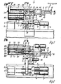
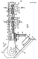
- bores 1 are made in a workpiece 2, e.g. the cylinder block of a motor vehicle engine, drilled with the aid of deep drilling tools 3, 3 '; it can be the so-called single-lip drilling method, the BTA method or the ejector method; the deep drilling tools are designed accordingly. They are picked up by drilling spindles 4, 4 'which are driven by motors 5, 5'. Drilling spindles 4, 4 'and motors 5, 5' are arranged on a slide 6 and can be moved in the direction of the workpiece 2 for the purpose of feed.
- the design of the deep drilling machine according to the invention now serves to remove the deep drilling tools 3, 3 'from the drilling spindles 4, 4' when they are worn - which is determined by measuring the contact pressure to produce a specific feed rate - in a magazine, generally designated 7 , and then new ones, ie Remove unused deep drilling tools from the magazine 7 and insert them again into the drilling spindle 4, 4 '.
- the deep drilling tools, insofar as they are inserted into the magazine 7, are designated by 23, 23 '. Two positions are possible (see Fig. 7a) by which worn and not yet worn deep drilling tools differ (see further below). When the tools have been pulled out of the magazine and / or are in the transport or working position, they are labeled 3, 3 '.
- the drilling spindles 4, 4 1 are equipped with suitable clamping devices.
- a suitable clamping device is for example in German patent application P 33 20 612.0-14 v. June 8, 1983 by the same applicant.
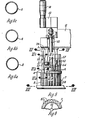
- the magazine 7 is shown schematically in FIG. 3 and in more detail in FIG. 8. It is formed by the fact that several of the receptacles 8, 3 1 , 3 1 or 23, 23 1, which are intended to hold the deep drilling tools, are arranged along a cylinder surface, as in the case of a drum turret magazine.
- the receiving tube 8 arranged on the far left in FIG. 6 and also on the cuts according to FIGS. 6a to 6c attached to it, only the rear third of the receiving tube 8 is designed with a full cross section. In the middle third, the cross-section is milled away over an angle of 90 ° to 110 °; 6c, the cross-section is milled away over an angle of somewhat more than 180 °.
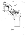
- the interchangeable arm 9 is pivoted in the direction of arrow 11 (FIG. 3) into the storage and loading position and places the deep drilling tools 3, 3 'on prisms 12, 12' (see also FIG. 5), which are stationary on Boom 13 are arranged, which is firmly connected to the deep drilling machine.
- the gripping tongs 10, 10 'are then opened; the deep drilling tools 3, 3 1 are claws 14, 14 'of a transport device in the receiving tubes. 8 of the magazine 7 inserted.
- a piston rod 17 acts on the web, which is arranged in a double-acting cylinder 18 and can be moved hydraulically in both directions.
- the drilling spindles 4, 4 1 include the deep drilling tools 23, 23 'in the position in which the deep drilling tools 3, 3' are located in FIG. 2.
- the interchangeable arm 9 pivots out of the position so that it cannot hinder the feed movement of the carriage 6.
- the next work cycle of the deep drilling machine with sharp deep drilling tools 23, 23 'can begin. As soon as the corresponding wear of these deep drilling tools is determined, the next change cycle begins.
- the plate 24 has at amounts picking tubes 8, with the stops 20, 20 'and the prisms 12, 12 are aligned with 1, recesses 25, 25. 1
- the stops 20, 20 'and the prisms 12, 12 are aligned with 1, recesses 25, 25. 1
- the plate 24 does not represent a stop, because the recesses 25, 25 1 are located there.
- the position of all sharp deep drilling tools 23, 23 'which - with the plate 80 folded away - are inserted as far as possible from the left into the receiving tubes 8 is clearly defined by a stop on the plate 24. See Fig. 5 at the top right and in Fig. 6 the deep drilling tool at the far left.
- the plate 80 can be folded away after loosening the handle 26.
- the different positions of the worn and the still unused sharp deep drilling tools are used to determine whether deep drilling tools that are pulled by the transport device 14-18 out of the receiving tubes 8 to the right into a position in which they are gripped by the gripping tongs 10, 10 ' of the change arm 9 can be detected, used or are still sharp. If there are worn out deep drilling tools, the machine switches off and emits a signal which prompts the magazine to be refilled with sharp deep drilling tools. In this way it is avoided that in the storage and loading position of the interchangeable arm 9 after the worn deep drilling tools have been deposited, the latter is loaded again with already worn deep drilling tools. It is ensured that the cycle of the tool change described runs as long as sharp, deep-drilling tools that have not yet been worn can be removed from the receiving tubes 8 of the magazine 7.
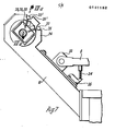
- a support plate 27 is arranged on the boom 13. It carries three proximity switches 28 to 30 in the direction of the position of the deep drilling tools in the magazine.
- a sharp deep drilling tool 23, 23 ' is shown, which lies with its front collar 31 on the stop plate 24, all proximity switches 28, 29, 30 are located short distance to an outer surface of the deep drilling tool. They therefore all have "contact” in the sense of their function with the deep drilling tool 23 or 23 ', thus supplying a signal with the logical value "1".
- the position of a deep drilling tool 3, 3 1 is shown in dash-dotted lines and is worn, ie its tips 19 and 19 1 rest against the stops 20, 20 '.
- the proximity switches 28, 29 and 30 deliver signals with the logical values "0", "1", "0".
- the various displays result from the truth table which belongs to FIG. 7a.
- the groove 32 has been used for this purpose, which at the same time enables the deep drilling tools to be removed from the receiving tubes 8 of the magazine 7 by means of the claws 14, 14 ' pull out.
- the interchangeable arm 9 is rotatably mounted in a bearing block 33 on the boom 13. It is supported in the working position according to FIGS. 1 to 3 in that a supporting part 34 connected to it rests on a counter bearing 35.
- the hydraulic rotary cylinder 36 provides the rotary drive of the change arm via a gear 37.
- Figures 4 and 5 show the transport device, more precisely: the mechanism for moving the claws 14, 14 '.
- Fig. 4 is an oblique top view of Fig. 3.
- the claws 14, 14 ' the shape of which can be seen from Fig. 4a, are - as already mentioned - attached to the rods 15, 15'.
- These rods 15, 15 ' are in turn connected to one another via the web 16 and can be displaced hydraulically in both directions via the piston rod 17 by means of the cylinder 18.
- the entire transport device formed by rods 15 with claws 14, and also by crossbar 16 and cylinder 18 must be tiltable. This is done in that the rods 15 and the cylinder .18 are guided in a housing formed by two parallel plates 38, 39 and the two transverse webs 40 and 41. This housing is fixedly attached to the swivel plate 42, which can be tilted around the shaft 44 in the bearing block 43.
- the bearing block 43 is arranged on the boom 13.
- the pivoting plate 42 is tilted by means of the hydraulically operated, double-acting cylinder 45, in which a piston rod 46 is guided, which engages on the pivoting plate 43 via the joint 47.
- the lower end of the pivot plate 42 is designed as a fork.
- the tilting is carried out in such a way that the individual parts assume the position shown in broken lines in FIG. 5, with this tilting position being shown only for the pivot plate 42, the rods 15 and the claws 14 for the sake of clarity.
- a flange 48 Connected to the crosspiece 41 is a flange 48 which, in the normal position shown, rests on the stop 49, which in turn engages is arranged on the plate 50, which is attached to the boom 13.
- the plate 50 also carries a stop bar 51 to which the claws 14, 14 'pull the deep drilling tool 23, 23' before the gripping tongs 10, 10 'grip it.
- FIG. 6 shows the magazine 7 with the receiving tubes 8 in detail.
- the receiving tubes. 8 are arranged on a cylinder 52 and held thereon by clamping pieces 53 which are screwed to the cylinder 52.
- the cylinder 52 is formed integrally with a hub 54.
- the hub 54 is connected to a shaft 55, which is supported in the bearing tube 56 by means of bearings 57.
- the bearing tube 56 is connected to the boom 13. The gradual and cyclical drive of the shaft 55, which brings the gradual rotation of the magazine 7, takes place via the motor 58 and the step gear 59.
- the exemplary embodiment described with reference to FIGS. 1 to 8 is based on the loading of a two-spindle deep drilling machine.
- two deep drilling tools are always removed from the two spindles 4, 4 'at the same time, placed in two receiving tubes 8 of the magazine 7 and at the same time two sharp tools 23, 23 1 again taken. This means that the distance between the gripping tongs 10, 10 '(FIG.
- the holding devices provided for the individual deep drilling tools in the magazine - are also arranged in pairs with the same distance must, the step movement with which the magazine continues to be rotated or - generally expressed: moved further - must be coordinated so that in each step a different pair opens up access to the transport device with two claws. If two deep drilling tools are removed from a pair of receiving tubes 8, these receiving tubes initially remain empty. The magazine remains in the position and resumes the same deep drilling tools as blunt tools after use. Then the magazine turns one step further and two sharp tools are removed.
- While the exemplary embodiment was based on a type of drum magazine, it is also possible to build up other magazines that do not rotate, but rather have receiving devices one above the other in different positions.
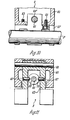
- FIG. 9 shows in detail the structure of the interchangeable arm 9. It is formed by a support 60 which is open at the bottom in cross section and is open at the bottom.
- a control slide 65 is displaceable in bearing bushes 64, 64 1 .
- This control slide 65 serves to pivot the pressure parts 62, 62 ', which are articulated at 66, 66' on the support 60, such that the deep drilling tools 3, 3 'or 23, 23 1 are clamped between them and the fixed stop parts 61, 61' .
- pins 67 (cf. FIG.
- the control slide 65 is movably connected via a fork connection 75 to the piston rod 76 of a double-acting hydraulically driven cylinder 77, to which medium under pressure is supplied via the connections 78 and 79, respectively.
- the entire arrangement depends on a very high accuracy of the positioning of the deep drilling tools with respect to the receiving openings of the drilling spindles 4, 4 '.
- the axis X of the deep drilling tools 3, 3 ' is lower than the pivot point Y of the change arm 9 by the distance h with respect to the horizontal, so that when the change arm 9 is pivoted away from it clamped deep drilling tool 3 or 3 'in the direction of arrow 11 initially results in a movement of the stop part 61 or 61 1 fixed on the carrier 60 laterally away from the deep drilling tool.
- Such a lateral movement component is given, however, if the axis X is arranged in the manner described below the pivot point Y by a certain amount h.
- FIGS. 9 to 11 also show how, with a similar construction, one or four or six gripping tongs can be provided on an interchangeable arm instead of two; this would be the case if, as mentioned above, correspondingly larger magazines, possibly with storage systems other than the drum-like structure, were used.
Landscapes
- Engineering & Computer Science (AREA)
- Mechanical Engineering (AREA)
- Automatic Tool Replacement In Machine Tools (AREA)
- Drilling And Boring (AREA)
Priority Applications (1)
| Application Number | Priority Date | Filing Date | Title |
|---|---|---|---|
| AT84110605T ATE38951T1 (de) | 1983-10-21 | 1984-09-06 | Wechselarm fuer eine vorrichtung zum werkzeugwechsel bei einer tiefbohrmaschine. |
Applications Claiming Priority (2)
| Application Number | Priority Date | Filing Date | Title |
|---|---|---|---|
| DE3338308 | 1983-10-21 | ||
| DE19833338308 DE3338308A1 (de) | 1983-10-21 | 1983-10-21 | Wechselarm fuer eine vorrichtung zum werkzeugwechsel bei einer tiefbohrmaschine |
Publications (3)
| Publication Number | Publication Date |
|---|---|
| EP0141152A2 true EP0141152A2 (fr) | 1985-05-15 |
| EP0141152A3 EP0141152A3 (en) | 1986-05-14 |
| EP0141152B1 EP0141152B1 (fr) | 1988-11-30 |
Family
ID=6212441
Family Applications (1)
| Application Number | Title | Priority Date | Filing Date |
|---|---|---|---|
| EP84110605A Expired EP0141152B1 (fr) | 1983-10-21 | 1984-09-06 | Bras de changement pour un changeur d'outils sur une aléseuse de trous profonds |
Country Status (3)
| Country | Link |
|---|---|
| EP (1) | EP0141152B1 (fr) |
| AT (1) | ATE38951T1 (fr) |
| DE (2) | DE3338308A1 (fr) |
Cited By (3)
| Publication number | Priority date | Publication date | Assignee | Title |
|---|---|---|---|---|
| CN107344300A (zh) * | 2017-08-18 | 2017-11-14 | 太仓吉井机械有限公司 | 一种自动更换枪钻的深孔钻床及控制方法 |
| WO2021028205A1 (fr) * | 2019-08-09 | 2021-02-18 | Tbt Tiefbohrtechnik Gmbh + Co | Machine de perçage en profondeur |
| WO2021186570A1 (fr) * | 2020-03-17 | 2021-09-23 | 株式会社ハイタック | Machine de foret à canon |
Families Citing this family (5)
| Publication number | Priority date | Publication date | Assignee | Title |
|---|---|---|---|---|
| US4807353A (en) * | 1988-03-28 | 1989-02-28 | R & B Machine Tool Company | Reciprocating tool spindle and tool changer mechanism operable during spindle backstroke |
| DE3912684A1 (de) * | 1989-03-21 | 1990-10-04 | Bueltmann Monika | Walzenstrasse zum profilwalzen von baendern (laengsnaht-rohrschweissen) |
| DE102019211997A1 (de) * | 2019-08-09 | 2021-02-11 | Tbt Tiefbohrtechnik Gmbh + Co | Tiefbohrmaschine |
| CN110834211B (zh) * | 2019-11-28 | 2020-12-01 | 灵璧县浩翔信息科技有限公司 | 一种用于管件的加工钻孔设备 |
| CN115122120A (zh) * | 2022-07-11 | 2022-09-30 | 江西万泰铝业有限公司 | 一种铝棒并列夹紧机构 |
Family Cites Families (9)
| Publication number | Priority date | Publication date | Assignee | Title |
|---|---|---|---|---|
| DE1552324C3 (de) * | 1966-07-13 | 1974-05-02 | Gebr. Heller Maschinenfabrik Gmbh, 7440 Nuertingen | Werkzeugmaschine mit automatischem Werkzeugwechsel |
| US3451125A (en) * | 1967-09-18 | 1969-06-24 | Carlton Machine Tool Co | Automatic tool changer |
| SE362816B (fr) * | 1968-03-14 | 1973-12-27 | Makino Milling Machine | |
| GB1324375A (en) * | 1970-10-02 | 1973-07-25 | Pullmax Ab | Tool changing devices in metal working machines |
| JPS501480A (fr) * | 1973-04-06 | 1975-01-09 | ||
| CH580469A5 (fr) * | 1974-03-22 | 1976-10-15 | Oerlikon Buehrle Ag | |
| DE2739534C2 (de) * | 1977-09-02 | 1983-09-08 | Dronsek, Max Günter, Dipl.-Ing., 8891 Klingen | Werkzeugwechselvorrichtung |
| US4221043A (en) * | 1979-03-05 | 1980-09-09 | Kearney & Trecker Corporation | Automatic tool changer for multiple spindle machine tool |
| JPS59227344A (ja) * | 1983-06-09 | 1984-12-20 | Sakazaki Tekko Kk | 多軸工作機械における自動工具交換装置 |
-
1983
- 1983-10-21 DE DE19833338308 patent/DE3338308A1/de active Granted
-
1984
- 1984-09-06 AT AT84110605T patent/ATE38951T1/de not_active IP Right Cessation
- 1984-09-06 DE DE8484110605T patent/DE3475383D1/de not_active Expired
- 1984-09-06 EP EP84110605A patent/EP0141152B1/fr not_active Expired
Cited By (5)
| Publication number | Priority date | Publication date | Assignee | Title |
|---|---|---|---|---|
| CN107344300A (zh) * | 2017-08-18 | 2017-11-14 | 太仓吉井机械有限公司 | 一种自动更换枪钻的深孔钻床及控制方法 |
| WO2021028205A1 (fr) * | 2019-08-09 | 2021-02-18 | Tbt Tiefbohrtechnik Gmbh + Co | Machine de perçage en profondeur |
| WO2021186570A1 (fr) * | 2020-03-17 | 2021-09-23 | 株式会社ハイタック | Machine de foret à canon |
| JP6989885B1 (ja) * | 2020-03-17 | 2022-02-14 | 株式会社ハイタック | ガンドリルマシン |
| US11498135B2 (en) | 2020-03-17 | 2022-11-15 | Hi-Tak Co., Ltd. | Gun drill machine |
Also Published As
| Publication number | Publication date |
|---|---|
| EP0141152B1 (fr) | 1988-11-30 |
| DE3338308C2 (fr) | 1988-10-13 |
| EP0141152A3 (en) | 1986-05-14 |
| DE3475383D1 (en) | 1989-01-05 |
| ATE38951T1 (de) | 1988-12-15 |
| DE3338308A1 (de) | 1985-05-09 |
Similar Documents
| Publication | Publication Date | Title |
|---|---|---|
| CH663737A5 (de) | Mehrspindel-drehautomat. | |
| DE2818018C2 (fr) | ||
| EP0700742A1 (fr) | Embarreur automatique pour machines-outil, en particulier pour tours automatiques | |
| DE1552485C3 (de) | Werkzeug für eine Werkzeugmaschine mit Werkzeugwechseleinrichtung und hierfür geeignete Werkzeugwechseleinrichtung | |
| DE2230144B2 (de) | Werkzeugsupport mit darin lotrecht verfahrbarem Meißelschieber mit einem dem Meißelschieber zugeordneten Werkzeugwechsler | |
| DE2143780A1 (de) | Werkzeugwechseleinrichtung für Werkzeugmaschinen | |
| DE2245481C3 (de) | Automatische Schneideinsatzwechselvorrichtung | |
| EP0141152B1 (fr) | Bras de changement pour un changeur d'outils sur une aléseuse de trous profonds | |
| DE102005003220B4 (de) | Werkzeugwechseleinrichtung und -verfahren | |
| DE3233934A1 (de) | Werkzeugmaschine mit werkzeugmagazin | |
| DE1777294B2 (de) | Werkzeugwechselvorrichtung fuer eine werkzeugmaschine | |
| DE19724635C2 (de) | Werkzeugmaschine mit Werkzeugauswechselvorrichtung | |
| EP0141153B1 (fr) | Magasin pour un changeur d'outils sur une aléseuse monobroche ou multibroche de trous profonds | |
| DE8318469U1 (de) | Stanzmaschine mit einer Vorrichtung zum Speichern und Wechseln von Werkzeugen | |
| EP0141154B1 (fr) | Echangeur d'outils pour une aléseuse de trous profonds | |
| DE3503637A1 (de) | Werkzeugmaschine fuer die spanabhebende bearbeitung von werkstuecken mit verschiedenen werkzeugen | |
| DE1552203B1 (de) | Einrichtung zum zufuehren der materialstange und abfuehren des stangenrestes an drehautomaten | |
| DE10323593A1 (de) | Werkzeugmaschine | |
| DE3326292C1 (de) | Vorrichtung zum Wechseln des Sägeblattes an einer Kreissägemaschine | |
| DE2616459C2 (fr) | ||
| DE8330376U1 (de) | Wechselarm zum Werkzeugwechsel bei einer mehrspindligen Tiefbohrmaschine | |
| DE3734688C1 (en) | Workpiece handling device on a lathe | |
| DE8330332U1 (de) | Einrichtung zum Werkzeugwechsel an einer Bohrmaschine | |
| DE8502937U1 (de) | Werkzeugmaschine fuer die spanabhebende bearbeitung von werkstuecken mit verschiedenen werkzeugen | |
| DE8330377U1 (de) | Magazin für eine Einrichtung zum Werkzeugwechsel an einer ein- oder mehrspindeligen Tiefbohrmaschine |
Legal Events
| Date | Code | Title | Description |
|---|---|---|---|
| PUAI | Public reference made under article 153(3) epc to a published international application that has entered the european phase |
Free format text: ORIGINAL CODE: 0009012 |
|
| AK | Designated contracting states |
Designated state(s): AT BE CH DE FR GB IT LI LU NL SE |
|
| ITCL | It: translation for ep claims filed |
Representative=s name: ING. ANTON AUSSERER |
|
| TCNL | Nl: translation of patent claims filed | ||
| EL | Fr: translation of claims filed | ||
| PUAL | Search report despatched |
Free format text: ORIGINAL CODE: 0009013 |
|
| RAP1 | Party data changed (applicant data changed or rights of an application transferred) |
Owner name: TBT TIEFBOHRTECHNIK GMBH UND CO. KG. |
|
| AK | Designated contracting states |
Kind code of ref document: A3 Designated state(s): AT BE CH DE FR GB IT LI LU NL SE |
|
| 17P | Request for examination filed |
Effective date: 19860422 |
|
| 17Q | First examination report despatched |
Effective date: 19870603 |
|
| GRAA | (expected) grant |
Free format text: ORIGINAL CODE: 0009210 |
|
| AK | Designated contracting states |
Kind code of ref document: B1 Designated state(s): AT BE CH DE FR GB IT LI LU NL SE |
|
| REF | Corresponds to: |
Ref document number: 38951 Country of ref document: AT Date of ref document: 19881215 Kind code of ref document: T |
|
| REF | Corresponds to: |
Ref document number: 3475383 Country of ref document: DE Date of ref document: 19890105 |
|
| GBT | Gb: translation of ep patent filed (gb section 77(6)(a)/1977) | ||
| ET | Fr: translation filed | ||
| ITF | It: translation for a ep patent filed | ||
| PG25 | Lapsed in a contracting state [announced via postgrant information from national office to epo] |
Ref country code: LU Free format text: LAPSE BECAUSE OF NON-PAYMENT OF DUE FEES Effective date: 19890930 |
|
| PGFP | Annual fee paid to national office [announced via postgrant information from national office to epo] |
Ref country code: GB Payment date: 19900823 Year of fee payment: 7 |
|
| PGFP | Annual fee paid to national office [announced via postgrant information from national office to epo] |
Ref country code: FR Payment date: 19900918 Year of fee payment: 7 |
|
| PGFP | Annual fee paid to national office [announced via postgrant information from national office to epo] |
Ref country code: CH Payment date: 19900921 Year of fee payment: 7 |
|
| PGFP | Annual fee paid to national office [announced via postgrant information from national office to epo] |
Ref country code: SE Payment date: 19900924 Year of fee payment: 7 |
|
| PGFP | Annual fee paid to national office [announced via postgrant information from national office to epo] |
Ref country code: LU Payment date: 19900926 Year of fee payment: 7 Ref country code: AT Payment date: 19900926 Year of fee payment: 7 |
|
| ITTA | It: last paid annual fee | ||
| PGFP | Annual fee paid to national office [announced via postgrant information from national office to epo] |
Ref country code: NL Payment date: 19900930 Year of fee payment: 7 |
|
| PGFP | Annual fee paid to national office [announced via postgrant information from national office to epo] |
Ref country code: BE Payment date: 19901005 Year of fee payment: 7 |
|
| PGFP | Annual fee paid to national office [announced via postgrant information from national office to epo] |
Ref country code: DE Payment date: 19901123 Year of fee payment: 7 |
|
| PG25 | Lapsed in a contracting state [announced via postgrant information from national office to epo] |
Ref country code: GB Effective date: 19910906 Ref country code: AT Effective date: 19910906 |
|
| PG25 | Lapsed in a contracting state [announced via postgrant information from national office to epo] |
Ref country code: SE Effective date: 19910907 |
|
| PG25 | Lapsed in a contracting state [announced via postgrant information from national office to epo] |
Ref country code: LI Effective date: 19910930 Ref country code: CH Effective date: 19910930 Ref country code: BE Effective date: 19910930 |
|
| PLBE | No opposition filed within time limit |
Free format text: ORIGINAL CODE: 0009261 |
|
| STAA | Information on the status of an ep patent application or granted ep patent |
Free format text: STATUS: NO OPPOSITION FILED WITHIN TIME LIMIT |
|
| 26N | No opposition filed | ||
| BERE | Be: lapsed |
Owner name: TBT TIEFBOHRTECHNIK G.M.B.H. UND CO. K.G. Effective date: 19910930 |
|
| PG25 | Lapsed in a contracting state [announced via postgrant information from national office to epo] |
Ref country code: NL Effective date: 19920401 |
|
| GBPC | Gb: european patent ceased through non-payment of renewal fee | ||
| NLV4 | Nl: lapsed or anulled due to non-payment of the annual fee | ||
| PG25 | Lapsed in a contracting state [announced via postgrant information from national office to epo] |
Ref country code: FR Effective date: 19920529 |
|
| REG | Reference to a national code |
Ref country code: CH Ref legal event code: PL |
|
| PG25 | Lapsed in a contracting state [announced via postgrant information from national office to epo] |
Ref country code: DE Effective date: 19920602 |
|
| REG | Reference to a national code |
Ref country code: FR Ref legal event code: ST |
|
| EUG | Se: european patent has lapsed |
Ref document number: 84110605.7 Effective date: 19920408 |