EP0141155A1 - Bunkerabzugsvorrichtung - Google Patents
Bunkerabzugsvorrichtung Download PDFInfo
- Publication number
- EP0141155A1 EP0141155A1 EP84110608A EP84110608A EP0141155A1 EP 0141155 A1 EP0141155 A1 EP 0141155A1 EP 84110608 A EP84110608 A EP 84110608A EP 84110608 A EP84110608 A EP 84110608A EP 0141155 A1 EP0141155 A1 EP 0141155A1
- Authority
- EP
- European Patent Office
- Prior art keywords
- bunker
- conveyor
- lifting
- outlet opening
- carrier
- Prior art date
- Legal status (The legal status is an assumption and is not a legal conclusion. Google has not performed a legal analysis and makes no representation as to the accuracy of the status listed.)
- Granted
Links
- 238000007599 discharging Methods 0.000 title abstract 2
- 239000002245 particle Substances 0.000 claims abstract description 5
- 239000010806 kitchen waste Substances 0.000 claims abstract description 3
- 239000004753 textile Substances 0.000 claims abstract description 3
- 239000000969 carrier Substances 0.000 claims description 3
- 239000000835 fiber Substances 0.000 claims description 2
- 238000003801 milling Methods 0.000 claims description 2
- 238000006073 displacement reaction Methods 0.000 claims 1
- 239000010813 municipal solid waste Substances 0.000 claims 1
- 239000000463 material Substances 0.000 abstract 2
- 241000273930 Brevoortia tyrannus Species 0.000 description 20
- 239000013590 bulk material Substances 0.000 description 15
- 229910000831 Steel Inorganic materials 0.000 description 7
- 239000010959 steel Substances 0.000 description 7
- 230000015572 biosynthetic process Effects 0.000 description 5
- 238000000605 extraction Methods 0.000 description 2
- 238000010586 diagram Methods 0.000 description 1
- 239000011120 plywood Substances 0.000 description 1
- 230000002787 reinforcement Effects 0.000 description 1
- 239000002699 waste material Substances 0.000 description 1
Images



Classifications
-
- B—PERFORMING OPERATIONS; TRANSPORTING
- B65—CONVEYING; PACKING; STORING; HANDLING THIN OR FILAMENTARY MATERIAL
- B65G—TRANSPORT OR STORAGE DEVICES, e.g. CONVEYORS FOR LOADING OR TIPPING, SHOP CONVEYOR SYSTEMS OR PNEUMATIC TUBE CONVEYORS
- B65G65/00—Loading or unloading
- B65G65/30—Methods or devices for filling or emptying bunkers, hoppers, tanks, or like containers, of interest apart from their use in particular chemical or physical processes or their application in particular machines, e.g. not covered by a single other subclass
- B65G65/34—Emptying devices
- B65G65/40—Devices for emptying otherwise than from the top
- B65G65/48—Devices for emptying otherwise than from the top using other rotating means, e.g. rotating pressure sluices in pneumatic systems
- B65G65/4881—Devices for emptying otherwise than from the top using other rotating means, e.g. rotating pressure sluices in pneumatic systems rotating about a substantially horizontal axis
-
- B—PERFORMING OPERATIONS; TRANSPORTING
- B65—CONVEYING; PACKING; STORING; HANDLING THIN OR FILAMENTARY MATERIAL
- B65G—TRANSPORT OR STORAGE DEVICES, e.g. CONVEYORS FOR LOADING OR TIPPING, SHOP CONVEYOR SYSTEMS OR PNEUMATIC TUBE CONVEYORS
- B65G33/00—Screw or rotary spiral conveyors
- B65G33/24—Details
- B65G33/32—Adaptations of bearings or couplings for supporting and connecting screws
-
- B—PERFORMING OPERATIONS; TRANSPORTING
- B65—CONVEYING; PACKING; STORING; HANDLING THIN OR FILAMENTARY MATERIAL
- B65G—TRANSPORT OR STORAGE DEVICES, e.g. CONVEYORS FOR LOADING OR TIPPING, SHOP CONVEYOR SYSTEMS OR PNEUMATIC TUBE CONVEYORS
- B65G65/00—Loading or unloading
- B65G65/30—Methods or devices for filling or emptying bunkers, hoppers, tanks, or like containers, of interest apart from their use in particular chemical or physical processes or their application in particular machines, e.g. not covered by a single other subclass
- B65G65/34—Emptying devices
- B65G65/40—Devices for emptying otherwise than from the top
- B65G65/46—Devices for emptying otherwise than from the top using screw conveyors
Definitions
- the invention relates to a bunker extraction device according to the preamble of claim 1.
- Bunkers for heavy and non-flowing bulk goods can not be designed with conical or sloping floors, but only with flat floors, so that the bulk material is removed via the discharge opening, which in a known device of this type is designed as a feed channel embedded in the bunker floor.
- the clear cross section of the outlet opening is determined by the conveyor element; it cannot therefore be chosen to be of any size.
- the clear cross section of the discharge opening can therefore not be dimensioned so large that a stable board formation of the bulk material above the discharge opening and the conveyor shaft is prevented. In this case, controlled bulk material removal is no longer possible.
- Bulk boards can form above the chute, especially after downtimes, when the large-area and band-shaped parts contained in the bulk material are layered in plywood in many layers and the small particles contained in the bulk material are diffusely reinforced hold tight. In such cases, the bunkers must then be cleared by hand, which is complex and time-consuming.
- the invention has for its object to provide a trigger device of the type mentioned so that the blockage of bunkers can either be prevented or removed in a mechanical manner - without the use of personnel.
- the conveying member can always be raised if there is a blockage above the outlet opening due to the formation of bulk boards in the bunker.
- the conveying member can always be raised if there is a blockage above the outlet opening due to the formation of bulk boards in the bunker.
- bulk goods boards in the area of the outlet opening are detected and destroyed, so that the outlet opening is kept free for bulk material which is pushing inward. This ensures continuous bulk material removal.
- the board formation can be avoided if the lifting movement of the conveying member takes place before a total blockage, e.g. B. by time-controlled, intermittent actuation or by control via a control circuit influenced by the electrical power consumption of the drive unit driving the switching movement which switches on when the electrical power consumption of its drive unit drops below a critical value as a result of the load on the drive unit being too low.
- the extraction device 1 is used to remove non-flowing or poorly flowing bulk material from a bunker 2, which contains a large proportion of long-fiber, large-area particles such as plastic bags, plastic sacks, textiles, cords, tapes, wires, kitchen waste, shredded household items and contains similar waste.
- the device 1 is arranged below a flat bunker floor 3. It consists essentially of a screw conveyor 4, which is located within a conveyor channel 5, 'and a lifting device 6 for lifting the screw 4 up to the height of a slot-shaped outlet opening 2' in the bunker floor 3. The passage cross section of this outlet opening 2 'is on the dimensions of the screw 4 adjusted.
- the outer periphery of the screw 4 is formed by its screw blades 7, which are equipped with tooth-like rippers 8 with which the bulk material or bulk material boards formed therefrom can be torn open and destroyed. As a result, the outlet opening 2 'is milled free in the event of a blockage.
- the lifting device 6 has on the two end faces 17, 17 'of the conveying channel 5 swivel arms 9, 10 which form carriers.
- the swivel arm 9 on the left in FIG. 1 consists of two identical steel plates 9 'and 9 "with projections 23, 24 projecting downwards. These are connected to one another via a plate 25.
- a base plate 26 designed as a rocker is articulated on the underside of the plate 25 who are a drive Unit 27 carries and with which the tension of a drive link 28 designed as a roller chain or belt drive is adjustable.
- the swivel arm 10 shown on the right in FIG. 1 consists of an elongated steel plate which is of the same design as the steel plates 9 'and 9''of the double-arm swivel arm 9.
- Both swivel arms 9, 10 represent single-arm levers with a pivot point, a load application point and a force application point represents.
- FIG. 2 shows the left steel plate 9 ′′, the right end 20 of which is pivotably mounted in a bearing block 41 with a bolt 39.
- a base plate 42 of the bearing block 41 is fastened to a profile carrier 22 which is fixedly connected to the bunker floor 3.
- the lifting cylinders 11, 12 are arranged, the piston rods 31, 34 of which are articulated by forks 33, 35 and bolts 32, 36 to the swivel arms.
- the lower cylinder sides each have an eye 37, 38 with a plug-in bolt which is pivotally mounted in a fork-shaped bearing block 37A which is fixed to the bunker floor 3.
- the ends 13 of the swivel arms 9, 10 are guided in forks 14 which are firmly connected to the end faces 17, 17 'of the delivery channel 5.
- the forks 14 made possible Lichen the vertical movement of the swivel arms 9, 10, the thrust of the screw 4 is absorbed and the stroke movement of the swivel arms 9, 10 is limited up and down by stops 15, 16.
- the height of the fork slot 29 is approximately equal to twice the width of the arm end 13.
- the bearing housing 18, 19 of the screw 4 are relatively close to the arm ends 13 and approximately half the width of the lugs 23, 24 of the carrier 9 ', 9 "of the swivel arm 9. From the articulation points of the Lift cylinders 11, 12 to the swivel arms 9, 10, the bearing housings 18, 19 have a distance which is smaller than the distance between the hydraulic piston articulation point and the axis of the bolts 39, so that the force for lifting the screw is correspondingly low.
- the screw 4 By actuating the lifting cylinders 11, 12, which can be hydraulic or pneumatic cylinders or can also be actuated by an electric motor, the screw 4 oscillates between its raised upper position (dash-dotted line in FIG. 2) and its lower, lowered position (dashed lines) Line in Fig. 2) moves.
- the lifting cylinders 11, 12 are hydraulic cylinders which are connected via the control circuit shown schematically in FIG. 3 to a hydraulic unit 43, to a pump M and to a control valve (not shown).
- the screw 4 is raised and lowered by turning on the pump M by actuating a switch (not shown) and at the same time controlling the control valve of the hydraulic unit 43 in such a way that a first hydraulic circuit 44 is closed.
- the worm 4 is advantageously connected via a control circuit (not shown) to an agitator arm 48 rotating about the bunker axis.
- This control circuit is selected so that the actuation of the lifting device 6 is only possible if the agitator arm 48 is in such a position that a collision between it and the raised screw 4 is excluded.
- an additional locking device is shown schematically at 49, with which the rotational movement of the agitator arm 48 can be interrupted when the screw 4 has reached its uppermost position and which can only be switched on again in the lower position of the screw.
- the agitator arm 48 can, for example, also be a broaching auger or a milling arm.
- the oscillating lifting movement of the screw 4 can also be controlled via a time switch (not shown), which is electrically connected to the screw and the agitator arm 48 and the pump M for actuating the lifting cylinders 11, 12. With this timer, the lifting device can be switched on and off in cycles at specific time intervals.
- a power meter (not shown) can also be provided, which measures the electrical power of the drive motor of the worm drive 27 and switches on the lifting device 6 whenever the worm has a minimum fill level and the worm drive torque and thus the electrical power consumption falls below a certain value . This is always the case when the outlet opening 2 'of the bunker floor 3 is blocked by bulk goods boards, so that no bulk material can fall into the conveying channel 5.
- FIGS. 4 and 5 differs from the previously described embodiment in that instead of the lifting cylinders 11, 12 eccentric discs 11a, 11a 'and 12a' on the swivel arm 9a or its steel plates 9a ', 9a "and the swivel arm 10a
- the eccentric disks 11a, 11a ', 12a are each of identical design and are mounted on a common shaft 50 which is supported by a base support (not shown) corresponding to the lifting cylinders 11, 12.
- the eccentric disks 11a, 11a', 12a are slightly thicker than the plate thickness of the associated steel plates 9a ', 9a "of the swivel arm 9a and thicker than the plate thickness of the swivel arm 10a, so that the circumferential surfaces of the eccentric discs have a wide, secure contact surface for the lower longitudinal edges 51, 52, 40 of the steel plates 9a, 9a" and the swivel arm 10.
- the eccentric disks 11a, 11a ', 12a lie approximately at the same distance from the ends of the swivel arms 9a, 10a as the lifting cylinders 11, 12 according to 1 and 2.
- the eccentric discs 11a, 11a 'and 12a are rotated by 90 ° in the direction of arrow P from their lower end position, shown in broken lines in FIGS. 4 and 5.
- the longitudinal edges 51, 52, 40 of the swivel arms 9a, 10a are at a minimal distance from the axis A of the eccentric shaft 50.
- the worm 4a projects with its outer circumferential zone 8a over the bunker floor 3a, so that bulk boards lying over the discharge opening 2a 'can be effectively torn open and destroyed.
- the lifting device 6a can be controlled either manually or automatically via a time switch or a power meter.
- a toggle lever (not shown) or a connecting rod (not shown) fastened to a shaft
- the worm can be raised in the same way by pivoting the toggle lever or by rotating the shaft of the connecting rod and can then be lowered again.
- the shaft ends 18b, 19b of the worm 4b are mounted in vertically movable carriages 9b , 10b , which instead of the swivel arms 9, 9a and 10, 10a according to FIGS. 1, 2 and 4 ' , 5 are provided as carriers.
- the slides 9b consist of approximately rectangular, vertically arranged plates with a lower, approximately V-shaped edge 66.
- the slides have a plurality of rollers 56 to 65 arranged one above the other on their longitudinal edges 54, 55.
- Two pairs of rollers 56, 64, 63 and 59, 65, 60 are arranged adjacent to the lower and an upper edge 66 and 67, the axes of which run parallel to the plate plane 9b.
- the rollers lying behind the rollers 56 and 59 in FIG. 6 are not shown in the drawings. Adjacent to and between these pairs of rollers is a roller 57, 58 or 61, 62, the axes of which are perpendicular to the plane of the plate.
- rollers 57, 58; 61, 62 are fastened to the plate side 69 (FIG. 6) facing away from the worm 4b via retaining tabs 70 to 73 (FIG. 7).
- the support 74 consists of two spaced-apart supports 75 and 76 which are U-shaped in cross-section and which are connected to one another via a cross strut 77 arranged in the lower half.
- the supports 75, 76 extend almost to the level of the bunker floor 3b and have at their ends 78, 79 holding parts 80, 81 which serve as fixed stops for the rollers.
- the slide 9b is aligned in its vertical position with respect to the support 74. They run when lifting and lowering the carriage 9b on strips 85, 86 which lie between the rollers and are fastened to the crossbars 87, 88 of the supports 75, 76.
- the strips 85, 86 have approximately the same length as the longitudinal edges 54, 56 of the slide 9b and adjoin directly below the holding parts 80, 81.
- the carriage 9b is supported on the crossbars 87, 88.
- the slide 9b is guided vertically and in the direction of the screw axis during its upward and downward movement.
- the pairs of rollers can run in a known manner in prismatic, round or flat guides.
- the two management levels are formed by separate, double pairs of rollers or by common, simple pairs of rollers.
- the piston rod 34b of the lifting cylinder 11b which is a hydraulic cylinder, is articulated via the bearing piece 33b.
- the lower cylinder 37b is held in a holder 90 fastened on the cross strut 77.
- the other carriage 10b is designed in a manner corresponding to that of the carriage 9b and how it is connected to a lifting cylinder 12b and guided in an associated support 91 in a vertically movable manner.
- the support 91 and the lifting cylinder 12b are also of the same design as the support 74 and the lifting cylinder 11b.
- the shaft end 19b of the screw 4b lying in a bearing opening of the slide 12b is connected to the screw drive 27b.
- the worm drive is fastened on a support piece 92 which is fastened to the carriage 10b at an upper end 93 and is guided on the support 91 at its lower end 94 by rollers 95, 96 which can be rotated about horizontal axes.
- the worm drive 27b which is designed as a spur gear with a sprocket countershaft, sits on a bracket which is fixedly connected to the slide 10b, so that the drive carries out the same oscillating movement as the worm.
- the lifting cylinders 11b, 12b are actuated, the carriages 9b, 10b are moved upward in the direction of arrow P until they rest on the holding parts 8 0 , 81, in which the screw 4b assumes the position shown in broken lines in FIG.
- the lifting cylinders 11b, 12b When the lifting cylinders 11b, 12b are lowered, they move in the opposite direction (arrow P ') down to the end position shown in FIGS. 6 and 7. This position is indicated in Fig. 8 by solid lines.
- the lifting device 6b which consists of carriages 9b, 10b and the lifting cylinders 11b, 12b, can be controlled depending on the power either manually or automatically via a timer or a power meter.
Landscapes
- Engineering & Computer Science (AREA)
- Mechanical Engineering (AREA)
- Filling Or Emptying Of Bunkers, Hoppers, And Tanks (AREA)
- Chutes (AREA)
- Discharge Of Articles From Conveyors (AREA)
- Refuse Collection And Transfer (AREA)
- Air Transport Of Granular Materials (AREA)
Abstract
Description
- Die Erfindung betrifft eine Bunkerabzugsvorrichtung nach dem Oberbegriff des Anspruches 1.
- Bunker für schwer- und nichtfließende Schüttgüter können nicht mit Konus- oder Schrägböden, sondern ausschließlich mit ebenen Böden ausgeführt werden, so daß die Entnahme des Schüttgutes über die Ausfallöffnung erfolgt, die bei einer bekannten Vorrichtung dieser Art als im Bunkerboden eingelassene Förderkanäle ausgeführt ist. Der lichte Querschnitt der Ausfallöffnung ist durch das Förderorgan bestimmt; sie kann daher nicht beliebig groß gewählt werden. Der lichte Querschnitt der Ausfallöffnung kann deshalb nicht so groß dimensioniert werden, daß eine standfeste Brettbildung des Schüttgutes oberhalb der Ausfallöffnung und des Förderschachtes verhindert wird. In diesem Fall ist ein kontrollierter Schüttgutabzug nicht mehr möglich.
- Zu einer Bildung von Schüttgutbrettern über dem Ausfallschacht kann es besonders nach Stillständen kommen, wenn sich die im Schüttgut enthaltenen großflächigen und bandförmigen Teile in vielen Lagen sperrholzartig übereinanderschichten und nach Art einer diffusen Armierung die kleinen,im Schüttgut enthaltenen Teilchen fest zusammenhalten. In solchen Fällen müssen die Bunker dann von Hand geräumt werden, was aufwendig und zeitraubend ist.
- Der Erfindung liegt die Aufgabe zugrunde, eine Abzugsvorrichtung der genannten Art so auszubilden, daß die Blockade von Bunkern entweder verhindert oder auf mechanische Weise - ohne Personaleinsatz - beseitigt werden kann.
- Diese Aufgabe wird erfindungsgemäß mit den kennzeichnenden Merkmalen des Anspruches 1 gelöst.
- Infolge der erfindungsgemäßen Ausbildung kann das Förderorgan immer dann angehoben werden, wenn es oberhalb der Ausfallöffnung zur Blockade durch Bildung von Schüttgutbrettern im Bunker kommt. Hierdurch werden Schüttgutbretter im Bereich der Auslaßöffnung erfaßt und zerstört, so daß die Auslaßöffnung für nachdrängendes Schüttgut freigehalten wird. Dadurch kann ein kontinuierlicher Schüttgutabzug sichergestellt werden.
- Die Brettbildung kann vermieden werden, wenn die Hubbewegung des Förderorgans noch vor einer Totalblockade erfolgt, z. B. durch zeitgesteuerte, intermittierende Betätigung oder durch Steuerung über einen von der elektrischen Leitungsaufnahme des das Förderorgan antreibenden Aggregats beeinflußten Regelkreis, der die Hubbewegung einschaltet, wenn infolge zu geringer Belastung des Förderorgans die elektrische Leistungsaufnahme seines Antriebsaggregats unter einen kritischen Wert absinkt.
- Weitere Merkmale der Erfindung ergeben sich aus den weiteren Ansprüchen, der Beschreibung und den Zeichnungen.
- Die Erfindung wird nachstehend anhand mehrerer in den Zeichnungen dargestellter Ausführungsbeispiele näher beschrieben. Es zeigt:
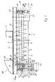
- Fig. 1 eine erfindungsgemäße Vorrichtung, die an einem Boden eines Bunkers angeordnet ist, in Seitenansicht,
- Fig. 2 die Vorrichtung nach Fig. 1 in Ansicht gemäß Pfeil II in Fig. 1,
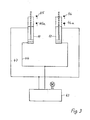
- Fig. 3 ein Schaltbild eines Hydrauliksystems der Vorrichtung nach den Fig. 1 und 2,
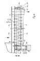
- Fig. 4 und 5 eine zweite Ausführungsform einer erfindungsgemäßen Vorrichtung in einer Darstellung entsprechend den Fig. 1 und 2,
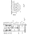
- Fig. 6 eine dritte Ausführungsform einer erfindungsgemäßen Vorrichtung in einer Darstellung entsprechend Fig. 1,
- Fig. 7 einen Schnitt längs der Linie VII-VII in Fig. 6 und
- Fig. 8 einen Schnitt längs der Linie VIII-VIII in Fig. 6.
- Die erfindungsgemäße Abzugsvorrichtung 1 nach den Fig. 1 und 2 dient zum Abziehen von nichtfließendem oder schwerfließendem Schüttgut aus einem Bunker 2, das einen hohen Anteil langfaseriger, großflächiger Partikel, wie Plastiktaschen, Plastiksäcke, Textilien, Schnüre, Bänder, Drähte, Küchenabfälle, zerkleinerte Haushaltsgegenstände und ähnliche Abfälle enthält. Die Vorrichtung 1 ist unterhalb eines ebenen Bunkerbodens 3 angeordnet. Sie besteht im wesentlichen aus einem als Schnecke ausgebildeten Förderorgan 4, das innerhalb eines Förderkanals 5 liegt,'und aus einer Hubeinrichtung 6 zum Anheben der Schnecke 4 bis in Höhe einer schlitzförmigen Ausfallöffnung 2' im Bunkerboden 3. Der Durchlaßquerschnitt dieser Ausfallöffnung 2' ist an die Abmessungen der Schnecke 4 angepaßt. Auch bei großem Schneckendurchmesser reicht der Durchlaßquerschnitt - besonders nach Stillständen - oft nicht aus, um zu verhindern, daß sich die im Schüttgut enthaltenen großflächigen und bandförmigen Teile in vielen Lagen sperrholzartig übereinanderschichten und nach Art einer diffusen Armierung die kleineren Partikel festhalten. Dadurch kann es oberhalb der Ausfallöffnung 2' zur Bildung standhafter Schüttgutbretter kommen. Um eine Blockade des Bunkers infolge dieser Brettbildung zu verhindern bzw. zu beseitigen und dadurch einen kontrollierten Abzug des Schüttgutes aus dem Bunker 2 zu gewährleisten, wird die Schnecke 4 mit der Hubeinrichtung 6 so angehoben, daß sie mit ihrem äußeren Umfang 7, 8 bis über den Bunkerboden 3 reicht. Der äußere Umfang der Schnecke 4 ist durch ihre Schneckenflügel 7 gebildet, die mit zahnartig ausgebildeten Aufreißern 8 bestückt sind, mit denen das Schüttgut oder hieraus gebildete Schüttgutbretter aufgerissen und zerstört werden können. Dadurch wird die Ausfallöffnung 2' bei einer Blockade freigefräst. Die Hubeinrichtung 6 weist an den beiden Stirnseiten 17, 17' des Förderkanals auf 5 angeordnete Schwenkarme 9, 10, die Träger bilden. Der in Fig. 1 linke Schwenkarm 9 besteht aus zwei gleichen Stahlplatten 9' und 9" mit nach unten ragenden Ansätzen 23, 24. Diese sind über eine Platte 25 miteinander verbunden. An der Unterseite der Platte 25 ist eine als Wippe ausgebildete Grundplatte 26 angelenkt, die ein Antriebsaggregat 27 trägt und mit der die Spannung eines als Rollenkette oder Riementrieb ausgebildeten Antriebsgliedes 28 einstellbar ist.
- Der in Fig. 1 rechts dargestellte Schwenkarn 10 besteht aus einer länglichen Stahlplatte, die gleich ausgebildet ist wie die Stahlplatten 9' und 9'' des doppelarmigen Schwenkarmes 9. Beide Schwenkarme 9, 10 stellen einarmige Hebel mit einem Drehpunkt, einem Lastangriffspunkt und einem Kraftangriffspunkt dar.
- Fig. 2 zeigt die linke Stahlplatte 9", deren rechtes Ende 20 mit einem Bolzen 39 in einem Lagerbock 41 schwenkbar gelagert ist. Eine Grundplatte 42 des Lagerbocks 41 ist an einem Profilträger 22 befestigt, der mit dem Bunkerboden 3 fest verbunden ist.
- Die in Fig. 1,2 dargestellten Schwenkarme tragen an den den drehbar gelagerten Enden 20 gegenüberliegenden Enden 13 je ein Lagergehäuse 18, 19 mit (nicht dargestellten) Pendelwälzlagern, in denen die stirnseitigen Lagerzapfen der Schnecke 4 gelagert sind. Zwischen dem Drehpunkt (Achsenbolzen 39) des Schwenkarmes 9 und dem Lagergehäuse 18, 19 sind die Hubzylinder 11, 12 angeordnet, deren Kolbenstangen 31, 34 durch Gabeln 33, 35 und Bolzen 32, 36 mit den Schwenkarmen gelenkig verbunden sind. Die unteren Zylinderseiten besitzen je ein Auge 37, 38 mit einem durchgesteckten Bolzen, der in einem zum Bunkerboden 3 ortsfesten, gabelförmigen Lagerbock 37A schwenkbar gelagert ist.
- Die Enden 13 der Schwenkarme 9, 10 sind in Gabeln 14 geführt, die fest mit den Stirnseiten 17, 17' des Förderkanals 5 verbunden sind. Die Gabeln 14 ermöglichen die Vertikalbewegung der Schwenkarme 9, 10, wobei die Schubkräfte der Schnecke 4 aufgenommen und die Hubbewegung der Schwenkarme 9, 10 nach oben und unten durch Anschläge 15, 16 begrenzt wird. Im Ausführungsbeispiel ist die Höhe des Gabelschlitzes 29 etwa gleich der doppelten Breite des Armendes 13.
- Wie die Fig. 1 und 2 zeigen, liegen die Lagergehäuse 18, 19 der Schnecke 4 relativ dicht benachbart zu den Armenden 13 und etwa in halber Breite der Ansätze 23, 24 der Träger 9', 9" des Schwenkarmes 9. Von den Anlenkpunkten der Hubzylinder 11, 12 an die Schwenkarme 9, 10 haben die Lagergehäuse 18, 19 einen Abstand, der kleiner ist als der Abstand zwischen dem Hydraulikkolben-Anlenkpunkt und der Achse der Bolzen 39, so daß die Kraft zum Heben der Schnecke entsprechend gering ist.
- Durch Betätigen der Hubzylinder 11, 12, die Hydraulik-oder Pneumatik-Zylinder sein können oder auch elektromotorisch betätigt werden können, wird die Schnecke 4 oszillierend zwischen ihrer angehobenen oberen Stellung (strichpunktierte Linie in Fig. 2) und ihrer unteren, abgesenkten Stellung (gestrichelte Linie in Fig. 2) bewegt. Im Ausführungsbeispiel sind die Hubzylinder 11, 12 Hydraulikzylinder, die über die in Fig. 3 schematisch dargestellte Steuerschaltung mit einem Hydraulikaggregat 43, mit einer Pumpe M und mit einem (nicht dargestellten) Steuerventil verbunden sind. Bei einer einfachen Ausführungsform erfolgt das Heben und Senken der Schnecke 4 dadurch, daß durch Betätigen eines (nicht dargestellten) Schalters die Pumpe M eingeschaltet und gleichzeitig das Steuerventil des Hydraulikaggregates 43 so gesteuert wird, daß ein erster Hydraulikkreis 44 geschlossen wird. Dadurch werden die Kolbenstangen31, 34 der Hubzylinder 11, 12 ausgefahren und dadurch die Schwenkarme 9, 10 bis in ihre obere Endstellung nach oben verschwenkt. In dieser Stellung sind die Hubzylinder 11, 12 mit einem in Fig. 3 bei 45 und 46 angedeuteten Kontakt in Berührung, während die Schwenkarme 9, 10 mit ihren Enden 13 am oberen Anschlag 15 der Gabel 14 anliegen. Der Schalter bleibt so lange eingeschaltet, bis das Schüttgut aufgerissen bzw. die Schüttgutbretter zerstört und dadurch die Ausfallöffnung 2' freigefahren sind. Anschließend wird der Schalter und damit die Pumpe M ausgeschaltet, wodurch ein zweiter Hydraulikkreis 47 (Fig. 3) geschlossen, die Kolbenstangen 31, 34 der Hubzylinder 11, 12 eingefahren und die Schwenkuntere arme 9, 10 bis in ihre/Endlage nach Fig. 2 (gestrichelte Linie) abgesenkt werden und dort mit unteren Kontakten 45a und 46a in Berührung stehen.
- Die Schnecke 4 ist vorteilhaft über eine (nicht dargestellte) Steuerschaltung mit einem um die Bunkerachse rotierenden Rührwerkarm 48 verbunden. Diese Steuerschaltung ist so gewählt, daß die Betätigung der Hubeinrichtung 6 nur dann möglich ist, wenn der Rührwerksarm 48 eine solche Lage hat, daß eine Kollision zwischen ihm und der angehobenen Schnecke 4 ausgeschlossen ist. In Fig. 1 ist bei 49 schematisch eine zusätzliche Verriegelung dargestellt, mit der die Rotationsbewegung des Rührwerkarmes 48 unterbrochen werden kann, wenn die Schnecke 4 ihre oberste Lage erreicht hat und die erst in der unteren Lage der Schnecke wieder eingeschaltet werden kann. Der Rührwerksarm 48 kann beispielsweise auch eine Räumschnecke oder ein Fräsarm sein.
- Anstelle der manuellen Schaltbetätigung kann die oszillierende Hubbewegung der Schnecke 4 auch über ein (nicht dargestelltes) Zeitschaltwerk gesteuert werden, das mit der Schnecke und dem Rührwerksarm 48 sowie der Pumpe M zum Betätigen der Hubzylinder 11, 12 elektrisch verbunden ist. Mit diesem Zeitschaltwerk kann die Ein- und Ausschaltung der Hubvorrichtung taktweise in bestimmten Zeitintervallen erfolgen.
- Anstelle des Zeitschaltwerkes kann ferner ein (nicht dargestelltes) Leistungsmeßgerät vorgesehen sein, das die elektrische Leistung des Antriebsmotors des Schneckenantriebes 27 mißt und die Hubeinrichtung 6 immer dann einschaltet, wenn die Schnecke einen minimalen Füllgrad und das Schneckenantriebsmoment und damit die elektrische Leistungsaufnahme einen bestimmten Wert unterschreiten. Dies ist dann immer der Fall, wenn durch Schüttgutbretter die Austrittsöffnung 2' des Bunkerbodens 3 blockiert ist, so daß kein Schüttgut in den Förderkanal 5 einfallen kann.
- Die Ausführungsform nach den Fig. 4 und 5 unterscheidet sich von der zuvor beschriebenen Ausführungsform dadurch, daß anstelle der Hubzylinder 11, 12 Exzenterscheiben 11a, 11a' und 12a' an dem Schwenkarm 9a bzw. seinen Stahlplatten 9a', 9a" und dem Schwenkarm 10a angreifen. Die Exzenterscheiben 11a, 11a', 12a sind jeweils gleich ausgebildet und auf einer gemeinsamen Welle 50 gelagert, die entsprechend den Hubzylindern 11, 12 von einer 'tnicht dargestellten) Bodenstütze getragen sind. Die Exzenterscheiben 11a, 11a', 12a sind geringfügig dicker als die Plattendicke der zugehörigen Stahlplatten-9a', 9a" des Schwenkarmes 9a und dicker als die Plattendicke des Schwenkarmes 10a, so daß die Umfangsflächen der Exzenterscheiben eine breite, sichere Auflagefläche für die unteren Längsränder 51, 52, 40 der Stahlplatten 9a, 9a" und des Schwenkarmes 10a bilden. Die Exzenterscheiben 11a, 11a', 12a liegen etwa mit gleichem Abstand von den Enden der Schwenkarme 9a, 10a wie die Hubzylinder 11, 12 gemäß Fig. 1 und 2. Zum Anheben der Schwenkarme 9a und 10a werden die Exzenterscheiben 11a, 11a' und 12a aus ihrer unteren, in den Fig. 4 und 5 mit gestrichelten Linien dargestellten Endlage um 90° in Richtung des Pfeiles P verdreht. In der Ausgangsstellung haben die Längsränder 51, 52, 40 der Schwenkarme 9a, 10a von der Achse A der Exzenterwelle 50 einen minimalen Abstand. In der oberen Endstellung, die in Fig. 5 mit strichpunktierten Linien eingezeichnet ist, ragt die Schnecke 4a mit ihrer äußeren Umfangszone 8a bis über den Bunkerboden 3a, so daß über der Ausfallöffnung 2a' liegende Schüttgutbretter wirksam aufgerissen und zerstört werden können. Sobald die Ausfallöffnung auf diese Weise vollständig freigelegt worden ist, werden die Exzenterscheiben 11a, 11a' und 12a in Pfeilrichtung P weitergedreht, bis sie wieder ihre Ausgangslage nach Fig. 5 haben und die Schwenkarme 9a, 10a sowie die Schnecke 4a ihre unterste Lage einnehmen.
- Die Hubeinrichtung 6a kann entsprechend wie bei der Ausführungsform nach den Fig. 1 bis 3 entweder von Hand oder automatisch über ein Zeitschaltwerk oder ein Leistungsmeßgerät gesteuert werden.
- Anstelle der Exzenterscheiben 11a, 11a', 12a kann auch ein (nicht dargestellter) Kniehebel oder eine nicht dargestellte , an einer Welle befestigte Pleuelstange vorgesehen sein, mit denen die Schnecke durch Verschwenken des Kniehebels bzw. durch Drehen der Welle der Pleuelstange in gleicher Weise angehoben und anschließend wieder abgesenkt werden kann.
- Bei der Ausführungsform nach den Fig. 6 bis 8 sind die Wellenenden 18b, 19b der Schnecke 4b in vertikal verfahrbaren Schlitten 9b, 10b gelagert, die anstelle der Schwenkarme 9, 9a und 10, 10a gemäß den Fig. 1, 2 bzw. 4', 5 als Träger vorgesehen sind.
- Wie insbesondere Fig. 7 zeigt, bestehen die Schlitten 9b aus etwa rechteckigen, vertikal angeordneten Platten mit einem unteren, etwa V-förmig verlaufenden Rand 66. Die Schlitten weisen an ihren Längsrändern 54, 55 mehrere übereinander angeordnete Laufrollen 56 bis 65 auf. Benachbart zum unteren und einen oberen Rand 66 und 67 sind jeweils zwei Rollenpaare 56, 64, 63 und 59, 65, 60 angeordnet, deren Achsen parallel zur Plattenebene 9b verlaufen. Von den Rollen sind die in Fig. 6 hinter den Rollen 56 und 59 liegenden Rollen in den Zeichnungen nicht dargestellt. Benachbart zu und zwischen diesen Rollenpaaren liegt jeweils eine Rolle 57, 58 bzw. 61, 62,deren Achsen senkrecht zur Plattenebene liegen. Diese Laufrollen 57, 58; 61, 62 sind an der von der Schnecke 4b abgewandten Plattenseite 69 (Fig. 6) über Haltelaschen 70 bis 73 (Fig. 7) befestigt. Mit den Laufrollen 56 bis 65 ist der Schlitten 9b in einer Stütze 74 der Hubvorrichtung 6b vertikal verfahrbar und einwandfrei gegenüber dieser sowie der Schnecke 4b ausgerichtet. Die Stütze 74 besteht aus zwei mit Abstand nebeneinander angeordneten und im Querschnitt jeweils U-förmigen Stützen 75 und 76, die über eine in der unteren Hälfte angeordnete Querstrebe 77 miteinander verbunden sind. Die Stützen 75, 76 erstrecken sich nahezu bis in Höhe des Bunkerbodens 3b und weisen an ihren Enden 78, 79 Halteteile 80, 81 auf, die als Festanschläge für die Laufrollen dienen. Sie sind an den von der Schneckenachse abgewandten Schenkeln 83, 84 der Längsstreben 75, 76 befestigt. Mit den Doppellaufrollen 56, 64; 59, 65 und 60, 63 ist der Schlitten 9b in seiner vertikalen Lage gegenüber der Stütze 74 ausgerichtet. Sie laufen beim Heben und Senken des Schlittens 9b an Leisten 85, 86, die zwischen den Laufrollen liegen und an den Querstegen 87, 88 der Stützen 75, 76 befestigt sind. Die Leisten 85, 86 haben etwa gleiche Länge wie die Längsränder 54, 56 des Schlittens 9b und schließen unmittelbar unterhalb der Halteteile 80, 81 an. Mit den anderen Laufrollen 57, 58, 61, 62 ist der Schlitten 9b auf den Querstegen 87, 88 abgestützt. über die Laufrollen 56 bis 65 ist der Schlitten 9b bei seiner Aufwärts- bzw. Abwärtsbewegung vertikal und in Richtung der Schneckenachse geführt. Hierzu können die Rollenpaare in bekannter Weise in Prismen-, Rund- oder Flachführungen laufen. Je nach Anordnung werden die beiden Führungsebenen durch separate, doppelte Rollenpaare oder durch gemeinsame, einfache Rollenpaare gebildet.
- Am unteren Rand 66 des Schlittens 9b ist die Kolbenstange 34b des Hubzylinders 11b, der ein Hydraulikzylinder ist, über das Lagerstück 33b angelenkt. Das untere Zylinderen - de 37b ist in einer auf der Querstrebe 77 befestigten Halterung 90 gehalten.
- Der andere Schlitten 10b ist entsprechend ausgebildet wie der Schlitten 9b und wie dieser mit einem Hubzylinder 12b verbunden und vertikal verfahrbar in einer zugehörigen Stütze 91 geführt. Die Stütze 91 und der Hubzylinder 12b sind ebenfalls gleich ausgebildet wie die Stütze 74 und der Hubzylinder 11b. Das in einer Lageröffnung des Schlittens 12b liegende Wellenende 19b der Schnecke 4b ist mit dem Schneckenantrieb 27b verbunden. Der Schneckenantrieb ist auf einem Tragstück 92 befestigt, das an einem oberen Ende 93 am Schlitten 10b befestigt ist und an seinem unteren Ende 94 mit um horizontale Achsen drehbaren Laufrollen 95, 96 an der Stütze 91 geführt ist. Der als Stirnradgetriebe mit Kettenrad-Vorgelege ausgebildete Schneckenantrieb 27b sitzt auf einer Konsole, die fest mit dem Schlitten10b verbunden ist, so daß der Antrieb gleiche Oszillierbewegung wie die Schnecke ausführt. Beim Betätigen der Hubzylinder llb, 12b werden die Schlitten 9b, 10b in Pfeilrichtung P nach oben bis zur Anlage an den Halteteilen 80, 81 gefahren, in der die Schnecke 4b die mit gestrichelten Linien dargestellte Lage in Fig.8 einnimmt. Beim Absenken der Hubzylinder llb, 12b bewegen sich diese in entgegengesetzter Richtung (Pfeil P') nach unten bis in die in den Fig. 6 und 7 dargestellte Endlage. Diese Lage ist in Fig. 8 durch ausgezogene Linien gekennzeichnet.
- Wie bei den zuvor beschriebenen Ausführungsbeispielen kann die Hubvorrichtung 6b, die aus Schlitten 9b, 10b und den Hubzylindern 11b, 12b besteht, entweder von Hand oder automatisch über ein Zeitschaltwerk oder ein Leistungsmeßgerät leistungsabhängig gesteuert werden.
Claims (10)
dadurch gekennzeichnet, daß das Förderorgan (4,4a,4b) höhenbeweglich angeordnet ist, derart, daß es mindestens mit einem radial äußeren Abschnitt (7, 8) in den Bereich der Auslaßöffnung (2') eintauchbar ist.
Priority Applications (1)
| Application Number | Priority Date | Filing Date | Title |
|---|---|---|---|
| AT84110608T ATE24463T1 (de) | 1983-09-10 | 1984-09-06 | Bunkerabzugsvorrichtung. |
Applications Claiming Priority (2)
| Application Number | Priority Date | Filing Date | Title |
|---|---|---|---|
| DE19833332703 DE3332703A1 (de) | 1983-09-10 | 1983-09-10 | Bunkerabzugsvorrichtung |
| DE3332703 | 1983-09-10 |
Publications (2)
| Publication Number | Publication Date |
|---|---|
| EP0141155A1 true EP0141155A1 (de) | 1985-05-15 |
| EP0141155B1 EP0141155B1 (de) | 1986-12-30 |
Family
ID=6208740
Family Applications (1)
| Application Number | Title | Priority Date | Filing Date |
|---|---|---|---|
| EP84110608A Expired EP0141155B1 (de) | 1983-09-10 | 1984-09-06 | Bunkerabzugsvorrichtung |
Country Status (3)
| Country | Link |
|---|---|
| EP (1) | EP0141155B1 (de) |
| AT (1) | ATE24463T1 (de) |
| DE (2) | DE3332703A1 (de) |
Cited By (2)
| Publication number | Priority date | Publication date | Assignee | Title |
|---|---|---|---|---|
| KR100924668B1 (ko) * | 2005-02-10 | 2009-11-03 | 도쿠리쓰교세이호징 가가쿠 기주쓰 신코 기코 | n 형 트랜지스터, n 형 트랜지스터 센서 및 n 형 트랜지스터용 채널의 제조 방법, 및 n 형 반도체적인 특성을 나타내는 나노 튜브형 구조체의 제조 방법 |
| IT201900003989A1 (it) * | 2019-03-19 | 2020-09-19 | Gucon Srl | Dispositivo a coclea |
Families Citing this family (1)
| Publication number | Priority date | Publication date | Assignee | Title |
|---|---|---|---|---|
| US5639202A (en) * | 1993-01-21 | 1997-06-17 | Magnificent Machinery, Inc. | Refuse bag opener |
Citations (2)
| Publication number | Priority date | Publication date | Assignee | Title |
|---|---|---|---|---|
| US3785512A (en) * | 1972-06-19 | 1974-01-15 | Royal Industries | Apparatus and method for feeding material from storage bins and the like |
| AT322443B (de) * | 1971-10-02 | 1975-05-26 | Saxlund As Zweigniederlassung | Vorrichtung zum austragen von gut aus einem bunker |
Family Cites Families (2)
| Publication number | Priority date | Publication date | Assignee | Title |
|---|---|---|---|---|
| FR2143573B1 (de) * | 1971-06-29 | 1977-06-03 | Taupin Andre | |
| DE2400547C3 (de) * | 1974-01-07 | 1978-06-29 | Saxlund Geb. Westerhus-Erichsen, Astrid Alice, 3040 Soltau | Bunker mit Austragvorrichtung |
-
1983
- 1983-09-10 DE DE19833332703 patent/DE3332703A1/de not_active Withdrawn
-
1984
- 1984-09-06 EP EP84110608A patent/EP0141155B1/de not_active Expired
- 1984-09-06 DE DE8484110608T patent/DE3461773D1/de not_active Expired
- 1984-09-06 AT AT84110608T patent/ATE24463T1/de not_active IP Right Cessation
Patent Citations (2)
| Publication number | Priority date | Publication date | Assignee | Title |
|---|---|---|---|---|
| AT322443B (de) * | 1971-10-02 | 1975-05-26 | Saxlund As Zweigniederlassung | Vorrichtung zum austragen von gut aus einem bunker |
| US3785512A (en) * | 1972-06-19 | 1974-01-15 | Royal Industries | Apparatus and method for feeding material from storage bins and the like |
Cited By (2)
| Publication number | Priority date | Publication date | Assignee | Title |
|---|---|---|---|---|
| KR100924668B1 (ko) * | 2005-02-10 | 2009-11-03 | 도쿠리쓰교세이호징 가가쿠 기주쓰 신코 기코 | n 형 트랜지스터, n 형 트랜지스터 센서 및 n 형 트랜지스터용 채널의 제조 방법, 및 n 형 반도체적인 특성을 나타내는 나노 튜브형 구조체의 제조 방법 |
| IT201900003989A1 (it) * | 2019-03-19 | 2020-09-19 | Gucon Srl | Dispositivo a coclea |
Also Published As
| Publication number | Publication date |
|---|---|
| DE3332703A1 (de) | 1985-03-28 |
| DE3461773D1 (en) | 1987-02-05 |
| EP0141155B1 (de) | 1986-12-30 |
| ATE24463T1 (de) | 1987-01-15 |
Similar Documents
| Publication | Publication Date | Title |
|---|---|---|
| DE4001859C2 (de) | Siebrechen zur Entnahme von festen Bestandteilen aus strömenden Flüssigkeiten | |
| DE1556165C3 (de) | Vorrichtung zur Bewegungssteuerung einzelner Gegenstande auf einem Sam melförderer | |
| EP0436187B1 (de) | Ladeeinrichtung für das Verladen von Haufwerk | |
| EP0230612A1 (de) | Seitenkratzer für Schüttguthalde | |
| EP0327104A2 (de) | Backenbrecher | |
| EP0472870B1 (de) | Pressvorrichtung für Abfälle, insbesondere für Müll | |
| DE10020909B4 (de) | Vorrichtung zur Förderung einer Vorratsrolle | |
| DE2912218A1 (de) | Zufuhreinrichtung fuer zerkleinerungsmaschinen | |
| DE2413198A1 (de) | Schneidvorrichtung | |
| DE2654475A1 (de) | Rechenanlage | |
| EP0141155B1 (de) | Bunkerabzugsvorrichtung | |
| DE2731588A1 (de) | Rotorenschere zum zerkleinern von insbesondere sperrigen abfaellen | |
| DE2929782C2 (de) | Vorrichtung zum Ausschneiden und Transportieren eines Gärfutterblockes | |
| DE4004138A1 (de) | Foerdereinrichtung fuer ballen, insbesondere bei oder in einer ballen- oder entdrahtungsstation | |
| DE2542908C2 (de) | Schere zum Schneiden von Altmaterial | |
| DE2836312C2 (de) | Ladewagen mit einer Schneideeinrichtung | |
| CH678312A5 (de) | ||
| DE2621624A1 (de) | Entmister | |
| DD208596A5 (de) | Austragungsvorrichtung fuer klebriges gut aus einem stehenden behaelter | |
| DE3739294C2 (de) | ||
| DE2223109A1 (de) | Raeumvorrichtung | |
| DE1269052B (de) | Kreisfoermiger Schlitzbunker mit Abzugseinrichtung | |
| CH467709A (de) | Fördervorrichtung | |
| DE1502852A1 (de) | Portalschere fuer flaches Walzgut mit aufwaertsgerichteter Schnittbewegung | |
| DE20210628U1 (de) | Bandfördereinrichtung |
Legal Events
| Date | Code | Title | Description |
|---|---|---|---|
| PUAI | Public reference made under article 153(3) epc to a published international application that has entered the european phase |
Free format text: ORIGINAL CODE: 0009012 |
|
| AK | Designated contracting states |
Designated state(s): AT BE CH DE FR GB IT LI NL SE |
|
| 17P | Request for examination filed |
Effective date: 19851005 |
|
| 17Q | First examination report despatched |
Effective date: 19860410 |
|
| GRAA | (expected) grant |
Free format text: ORIGINAL CODE: 0009210 |
|
| AK | Designated contracting states |
Kind code of ref document: B1 Designated state(s): AT BE CH DE FR GB LI NL SE |
|
| REF | Corresponds to: |
Ref document number: 24463 Country of ref document: AT Date of ref document: 19870115 Kind code of ref document: T |
|
| ET | Fr: translation filed | ||
| REF | Corresponds to: |
Ref document number: 3461773 Country of ref document: DE Date of ref document: 19870205 |
|
| PLBE | No opposition filed within time limit |
Free format text: ORIGINAL CODE: 0009261 |
|
| STAA | Information on the status of an ep patent application or granted ep patent |
Free format text: STATUS: NO OPPOSITION FILED WITHIN TIME LIMIT |
|
| 26N | No opposition filed | ||
| PGFP | Annual fee paid to national office [announced via postgrant information from national office to epo] |
Ref country code: GB Payment date: 19910806 Year of fee payment: 8 |
|
| PGFP | Annual fee paid to national office [announced via postgrant information from national office to epo] |
Ref country code: AT Payment date: 19910823 Year of fee payment: 8 |
|
| PGFP | Annual fee paid to national office [announced via postgrant information from national office to epo] |
Ref country code: BE Payment date: 19910830 Year of fee payment: 8 |
|
| PGFP | Annual fee paid to national office [announced via postgrant information from national office to epo] |
Ref country code: SE Payment date: 19910920 Year of fee payment: 8 |
|
| PGFP | Annual fee paid to national office [announced via postgrant information from national office to epo] |
Ref country code: NL Payment date: 19910930 Year of fee payment: 8 Ref country code: FR Payment date: 19910930 Year of fee payment: 8 |
|
| PGFP | Annual fee paid to national office [announced via postgrant information from national office to epo] |
Ref country code: DE Payment date: 19911126 Year of fee payment: 8 |
|
| PGFP | Annual fee paid to national office [announced via postgrant information from national office to epo] |
Ref country code: CH Payment date: 19911211 Year of fee payment: 8 |
|
| PG25 | Lapsed in a contracting state [announced via postgrant information from national office to epo] |
Ref country code: GB Effective date: 19920906 Ref country code: AT Effective date: 19920906 |
|
| PG25 | Lapsed in a contracting state [announced via postgrant information from national office to epo] |
Ref country code: SE Effective date: 19920907 |
|
| PG25 | Lapsed in a contracting state [announced via postgrant information from national office to epo] |
Ref country code: LI Effective date: 19920930 Ref country code: CH Effective date: 19920930 Ref country code: BE Effective date: 19920930 |
|
| BERE | Be: lapsed |
Owner name: SCHWABISCHE HUTTENWERKE G.M.B.H. Effective date: 19920930 |
|
| PG25 | Lapsed in a contracting state [announced via postgrant information from national office to epo] |
Ref country code: NL Effective date: 19930401 |
|
| GBPC | Gb: european patent ceased through non-payment of renewal fee |
Effective date: 19920906 |
|
| NLV4 | Nl: lapsed or anulled due to non-payment of the annual fee | ||
| PG25 | Lapsed in a contracting state [announced via postgrant information from national office to epo] |
Ref country code: FR Effective date: 19930528 |
|
| REG | Reference to a national code |
Ref country code: CH Ref legal event code: PL |
|
| PG25 | Lapsed in a contracting state [announced via postgrant information from national office to epo] |
Ref country code: DE Effective date: 19930602 |
|
| REG | Reference to a national code |
Ref country code: FR Ref legal event code: ST |
|
| EUG | Se: european patent has lapsed |
Ref document number: 84110608.1 Effective date: 19930406 |