EP0141177A2 - Apparatus for compressing fibrous-cement slabs - Google Patents
Apparatus for compressing fibrous-cement slabs Download PDFInfo
- Publication number
- EP0141177A2 EP0141177A2 EP84110759A EP84110759A EP0141177A2 EP 0141177 A2 EP0141177 A2 EP 0141177A2 EP 84110759 A EP84110759 A EP 84110759A EP 84110759 A EP84110759 A EP 84110759A EP 0141177 A2 EP0141177 A2 EP 0141177A2
- Authority
- EP
- European Patent Office
- Prior art keywords
- belts
- press
- toothed
- pressing
- conveyor belts
- Prior art date
- Legal status (The legal status is an assumption and is not a legal conclusion. Google has not performed a legal analysis and makes no representation as to the accuracy of the status listed.)
- Granted
Links
Images

Classifications
-
- B—PERFORMING OPERATIONS; TRANSPORTING
- B28—WORKING CEMENT, CLAY, OR STONE
- B28B—SHAPING CLAY OR OTHER CERAMIC COMPOSITIONS; SHAPING SLAG; SHAPING MIXTURES CONTAINING CEMENTITIOUS MATERIAL, e.g. PLASTER
- B28B1/00—Producing shaped prefabricated articles from the material
- B28B1/52—Producing shaped prefabricated articles from the material specially adapted for producing articles from mixtures containing fibres, e.g. asbestos cement
- B28B1/528—Producing shaped prefabricated articles from the material specially adapted for producing articles from mixtures containing fibres, e.g. asbestos cement for producing corrugated sheets
-
- B—PERFORMING OPERATIONS; TRANSPORTING
- B28—WORKING CEMENT, CLAY, OR STONE
- B28B—SHAPING CLAY OR OTHER CERAMIC COMPOSITIONS; SHAPING SLAG; SHAPING MIXTURES CONTAINING CEMENTITIOUS MATERIAL, e.g. PLASTER
- B28B13/00—Feeding the unshaped material to moulds or apparatus for producing shaped articles; Discharging shaped articles from such moulds or apparatus
- B28B13/02—Feeding the unshaped material to moulds or apparatus for producing shaped articles
-
- B—PERFORMING OPERATIONS; TRANSPORTING
- B28—WORKING CEMENT, CLAY, OR STONE
- B28B—SHAPING CLAY OR OTHER CERAMIC COMPOSITIONS; SHAPING SLAG; SHAPING MIXTURES CONTAINING CEMENTITIOUS MATERIAL, e.g. PLASTER
- B28B13/00—Feeding the unshaped material to moulds or apparatus for producing shaped articles; Discharging shaped articles from such moulds or apparatus
- B28B13/04—Discharging the shaped articles
Definitions
- the invention relates to a system for pressing fiber cement slabs, which first lie in the form of a fiber cement mat in the middle on a press base with symmetrically arranged, lateral manipulation surfaces between them and into a press point of a press and then as pressed plates on the press base from the press point can be transported by means of a transport device.
- a prefabricated fiber cement mat is transferred to a delivered press base.
- the loaded underlay is transported to a press in a pressing point and, positioned there, pressed with the mat.
- the base with the pressed plate is transported out of the pressing point.
- the plate is then removed from the base and the empty base is transported back to the start of the system in order to be loaded again with a fiber cement mat to be pressed.
- a number of the press pads circulate in the process at a speed of, for example, 3 m / sec and in a sequence of, for example, 12 seconds.
- tilting or slipping of the press documents to be transported is to be avoided, thereby ensuring their exact positioning in the individual treatment or manipulation stations without bruising.
- the transport device should be relatively simple and also applicable for systems with presses with two pressing points arranged one above the other.
- the transport device in order to accommodate the pressing pads with the plates, has two conveyor belts running parallel to one another along the pressing point, the relative spacing and width of which is the distance and the width of the manipulation surfaces of the pressing pads, which are exposed on the belts for transport come, correspond to which tapes, both of the same length, are provided with their length in a regular spaced succession to the tape, fixed engagement points, to which tapes a drive device is assigned, which has engagement points designed for engaging the engagement points, the drive device to synchronous movement of the two belts, ie at the same speed at the same time.
- the conveyor belts are designed as toothed belts, the regularly arranged teeth of which form the engagement points, the pitch and tooth shape of the toothed belts being provided in accordance with toothed drive gearwheels which form the engagement elements of the drive device.
- timing belts are available on the market and the transport device equipped with them works reliably and practically maintenance-free.
- the system shown in FIG. 1 is used to press fiber cement boards 1.
- fiber cement boards 1 First, in the form of a fiber cement mat, these are, as shown in FIG. 2, on a press base 2 which has lateral manipulation surfaces 3 arranged symmetrically in parallel.
- the plate 1 thus lies between the manipulation surfaces 3.
- the base 2 is perforated in the area covered by the plate 1, for removing the liquid to be pressed out of the mat during pressing.
- the underlay 2 is corrugated in this area.
- the M anipulations vom 3 are each planar and lie in the same plane.
- the base 2 with the plate 1 is transported into a pressing point 4 of a press 5 and after the pressing, when the plate 1 has been pressed, the base 2 with the plate 1 transported out of the pressing point 4.
- the pressing point is formed by pressing stamps 7, which cover the format of the plate 1, so that the manipulation surfaces 3 of the base 2 lie outside and parallel along the pressing point when the plate 1 with the base 2 is positioned in the pressing point 4.
- the transport device 6 has two conveyor belts 8. They run parallel to each other along the pressing point 4 through the press 5.
- the distance between the belts 8 and their width correspond to the relative distance and the width of the manipulation surfaces 3 of the press pads 2.
- the spacing between successive engagement points 9 which are fixed to the belt 8 is provided.
- a drive device 10 is assigned to these conveyor belts 8, which has engagement elements 11 which are designed corresponding to the engagement points 9 and engage in the engagement points.
- the drive device 10 is designed to move the belts 8 synchronously. It thus serves to move the belts 8 at the same speed and at the same time.
- the conveyor belts are designed as toothed belts 8, the teeth 9 of which are regularly arranged in length and form the engagement points.
- the drive device 10 has a drive gear 11 assigned to each toothed belt 8, which is toothed according to the pitch and tooth shape of the toothed belt 8 and forms the mentioned engagement element.
- only one side of the toothed belt 8 is toothed and the other side is smooth. It can be seen that the toothed belt 8, with its toothed side, faces a press base 2 to be transported, which is transported exposed on the toothed belt 8.
- the toothed belt 8 is guided by means of two deflection rollers 12, so that it forms a loop around the drive toothed wheel 11. There is a loop in the range of 180 °.
- the deflection rollers 12 serve as tension rollers for the toothed belt 8.
- a toothed belt made of reinforced plastic is best suited for this transport device. Its smooth side should have good sliding properties compared to a guide pad 13, which is provided for its guidance and is made of plastic, for example. Such a timing belt is available on the market. It is also conceivable to use a liquid film, e.g. to provide a hydrostatically constructed liquid layer between the toothed belt 8 and the guide pad 13 in order to achieve wear-free conditions in the present case.
- the two toothed belts 8 move absolutely synchronously and conformally. This means that there is no relative instantaneous displacement of one toothed belt relative to the other in the pair.
- the relatively heavy press pad 2 with the plate 1 is free but non-slipping on the toothed belt and cannot be shifted and / or tilted due to the momentary delay or advance of one belt relative to the other and can thus be positioned exactly at a desired point on the transport route.
- the surfaces of the conveyor belts 8 and the manipulation surfaces 3 of the press pads 2 facing or coming into contact with one another are to be provided with a non-slip surface in the case of the toothed belt only for the manipulation surfaces . Then a non-slip fit of the press pad on the belts is safely achieved.
- the transport device 6 is divided into three sections: a section 6 1 , which leads through the press 5, is preceded by a section 6 2 , which serves as a waiting station , and a section 6 3 downstream, which serves as a parking station.
- Each of the three sections 6 1 , 6 2 , 6 3 has a pair of conveyor belts 8 1 , 8 2 , 8 3 in its area.
- Each pair is separated from the other in terms of drive and is equipped with its own, specifically commanded and adjustable drive device 10 1 , 10 2 , 10 3 . Every drive forward direction is driven by its own, specially commanded and adjustable DC motor M.
- the system shown in Figure 1 is equipped with a press 5 with two pressing points 4 1 and 4 2 arranged one above the other.
- This press presses two plates at once in one work cycle.
- Each of the pressing points 4 1 and 4 2 is assigned a transport device 6.
- the transport of the press documents 2 with the plates 1 takes place simultaneously in the same cycle in a lower and in an upper floor.
- the upper floor is shown in dashed lines in the drawing.
- Prefabricated fiber cement mats are placed on the press pads in a charging station 14.
- the pad lies on a conveyor belt 15 of the station and waits there until the mat is put on.
- the finished pressed fiber cement boards are removed from the press documents into a removal station 16, on the left in the picture, lying on a conveyor belt 17 of the station.
- the conveyor belts 15 and 17 of the loading and unloading stations are at the level of the lower transport floor mentioned above.
- Every second loaded press pad coming from the charging station is raised from the level of the lower level to the level of the above-mentioned upper level and, after pressing, is lowered to the level of the lower level. This happens in the area of the waiting station 6 2 or in the area of the parking station 6 3 .
- a waiting or parking station for this purpose is shown in more detail in FIG. 3.
- the conveyor belts 8 of the upper floor are arranged on a frame 20 so as to be laterally displaceable, so that the relative distance between the belts can be increased over the width of the press base. If the tapes are in this spread position, the press pad can be transported between them in the vertical direction.
- This vertical transport is provided by a lifting table with a horizontal table top 21, which can be moved by means of a lifting device 22 into an upper position above the level of the upper level and into a lower position below the level of the lower level.
- the base After simultaneous movement of the belts 15 and the adjoining belts 8 2 , the base is positioned in the waiting station 6 2 on the lower belts 8 2 .
- the table top 21 is in its lower position.
- the upper conveyor belts of the waiting station 6 2 are spread and are in the position shown at the top right in FIG. 3, so that the underlay can be transported between them.
- the table top 21 moves to its upper position and lifts the support above the level of the upper floor.
- the upper bands return and are below the manipulation areas of the underlay. This position can be seen in the top left of Figure 3.
- the table top 21 returns to its lower position and the first mat comes to rest on the upper belts.
- a second, meanwhile loaded document comes to the lower level of the waiting station 6 2 .
- the pressing points 4 1 and 4 2 of the press 5 open.
- the first and the second loaded underlay are positioned in the relevant pressing points.
- the pressing process is completed and the pressing points 4 1 and 4 2 are opened.
- the first and the second support are simultaneously moved into the parking statutes 6 3 and positioned there.
- the belts 8 2 and 8 1 on the two floors transport the next two waiting documents to the pressing points 4 1 and 4 2 .
- the underlay located on the lower level is moved into the unloading station 16 by simultaneously moving the lower belts 8 3 and the adjoining belts 17 and the pressed plate is removed from the underlay.
- the empty pad is transported back to the charging station 14 via a transport path.
- the table top 21 in the parking station 6 3 goes into its upper position and thus lifts the surface previously lying on the upper belts.
- the upper belts return to their closer position and are thus ready to take over another press pad.
- the base which has been converted from top to bottom is inserted into the unloading station drive and after removal of the fiber cement board, the empty base is transported back to the charging station 14 via the above-mentioned transport route.
- the system works continuously and the described transport of the documents is regulated in accordance with the cycle of the press 5.
- the loading and unloading of the documents takes place in stations 14 and 16 in half a cycle.
- the transfer of every second document from one floor to the other in stations 6 2 and 6 3 also takes place within the period of half a cycle.
- the transport devices in stations 14 and 16, i.e. the conveyor belts 15 and 17 and the drive devices 18 and 19 are also designed in accordance with the described invention. With the same means, the return of the empty documents can be solved.
Landscapes
- Engineering & Computer Science (AREA)
- Ceramic Engineering (AREA)
- Manufacturing & Machinery (AREA)
- Chemical & Material Sciences (AREA)
- Mechanical Engineering (AREA)
- Press-Shaping Or Shaping Using Conveyers (AREA)
- Structure Of Belt Conveyors (AREA)
- Cultivation Of Seaweed (AREA)
- Curing Cements, Concrete, And Artificial Stone (AREA)
- Spinning Methods And Devices For Manufacturing Artificial Fibers (AREA)
- Diaphragms For Electromechanical Transducers (AREA)
- Sampling And Sample Adjustment (AREA)
- Chemical Or Physical Treatment Of Fibers (AREA)
- Preparation Of Clay, And Manufacture Of Mixtures Containing Clay Or Cement (AREA)
- Intermediate Stations On Conveyors (AREA)
- Devices For Post-Treatments, Processing, Supply, Discharge, And Other Processes (AREA)
- Inorganic Fibers (AREA)
- Delivering By Means Of Belts And Rollers (AREA)
Abstract
@ In einer Anlage zum Pressen von Faserzementplatten werden zwischen Manipulationsflächen (3) einer Pressunterlage (2) liegende Faserzementmatten (1) in einer Pressungsstelle einer Presse verpresst. Die beladenen Pressunterlagen (2) werden zu der Pressungsstelle hinein und heraus mittels einer Transportvorrichtung transportiert. Zum Verhindern eines Verrutschens bzw. Verkantens der Unterlagen (2) während des Transports und so zur Sicherstellung ihrer genauen Positionierung mindestens an der Pressungsstelle weist die Transportvorrichtung zwei zueinander parallel entlang der Pressungsstelle verlaufende Transportbänder (8) auf, deren relativer Abstand und Breite dem Abstand und der Breite der Manipulationsflächen (3) der Pressunterlagen entsprechen. Die Pressunterlagen werden auf den Transportbändern (8) frei liegend transportiert. Die Bänder (8) sind, beide gleich, mit ihrer Länge nach im regelmässigen, gleichen Abstand aufeinander folgenden, zum Band ortsfesten Eingriffsstellen (9) versehen. Den Bändern (8) ist eine Antriebsvorrichtung (10) zugeordnet, die den Eingriffsstellen (9) entsprechend ausgebildete, in die Eingriffsstellen (9) eingreifende Eingriffselemente (11) aufweist. Die Antriebsvorrichtung (10) ist zu synchronem Bewegen der beiden Bänder (8), d.h. mit gleicher Geschwindigkeit zu gleicher Zeit ausgeführt. In einer bevorzugten Ausführungsform sind die Transportbänder Zahnriemen (8), deren Zähne (9) die Eingriffsstellen bilden, und die Eingriffselemente sind entsprechend der Teilung und der Zahnform der Zahnriemen (8) verzahnte Antriebszahnräder (11). Die Synchronisation der beiden Zahnriemen (8) ist mittels einer gemeinsamen Welle der Antriebszahnräder (11) gegeben, die einem regulierbaren Gleichstrommotor (M) zugekoppelt ist.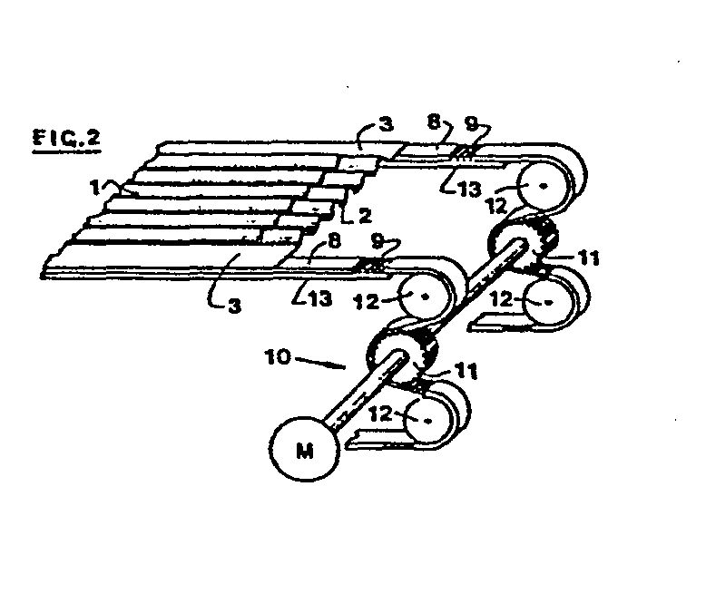
Description
Die Erfindung bezieht sich auf eine Anlage zum Pressen von Faserzementplatten, welche zuerst in Form einer Faserzementmatte mittig auf einer Pressunterlage mit symmetrisch angeordneten, seitlichen Manipulationsflächen zwischen diesen liegen und hinein zu einer Pressungsstelle einer Presse und danach als gepresste Platten auf der Pressunterlage von der Pressungsstelle heraus mittels einer Transportvorrichtung transportiert werden.The invention relates to a system for pressing fiber cement slabs, which first lie in the form of a fiber cement mat in the middle on a press base with symmetrically arranged, lateral manipulation surfaces between them and into a press point of a press and then as pressed plates on the press base from the press point can be transported by means of a transport device.
In einem heute üblichen kontinuierlichen Herstellungsprozess von Faserzementplatten wird eine prefabrizierte Faserzementmatte auf eine zugestellte Pressunterlage umgesetzt. Die beladene Unterlage wird zu einer Presse in eine Pressungsstelle transportiert und, dort positioniert, mit der Matte abgepresst. Nach dem Pressungsvorgang wird die Unterlage mit der gepressten Platte von der Pressungsstelle heraustransportiert. Anschliessend wird die Platte von der Unterlage abgenommen und die leere Unterlage wird zurück zum Anfang der Anlage transportiert,um dort erneut mit einer zu pressenden Faserzementmatte beladen zu werden. Üblicherweise zirkulieren eine Anzahl der Pressunterlagen in dem Prozess mit einer Geschwindigkeit von zum Beispiel 3 m/sek und in einer Sequenz von zum Beispiel 12 Sekunden. Dabei arbeitet eine solche Anlage automatisch, und aus Sicherheitsgründen ist ein Eingriff der menschlichen Hand ausgeschlossen. Es wird eine ununterbrochene Produktion rund um die Uhr verlangt. Dementsprechend werden an die Verlässlichkeit des Transportes der Pressunterlagen beziehungsweise der beladenen Pressunterlagen hohe Ansprüche gestellt, insbesondere was eine genaue Positionierung an den erwähnten Behandlungs- oder Manipulationsstationen der Anlage betrifft. Der Transport ist auch deswegen schwierig zu gewährleisten, da die zirkulierenden Pressunterlagen hauptsächlich bei dem Pressen beeinträchtigt werden und mehr oder weniger verformt, zum Beispiel nicht mehr ideal plan, transportiert werden müssen.In a continuous manufacturing process of fiber cement boards, which is common today, a prefabricated fiber cement mat is transferred to a delivered press base. The loaded underlay is transported to a press in a pressing point and, positioned there, pressed with the mat. After the pressing process, the base with the pressed plate is transported out of the pressing point. The plate is then removed from the base and the empty base is transported back to the start of the system in order to be loaded again with a fiber cement mat to be pressed. Typically, a number of the press pads circulate in the process at a speed of, for example, 3 m / sec and in a sequence of, for example, 12 seconds. Such a system works automatically, and for safety reasons an intervention by the human hand is impossible. Continuous production around the clock is required. Accordingly, high demands are placed on the reliability of the transport of the press documents or the loaded press documents, in particular with regard to precise positioning at the treatment or manipulation stations of the system mentioned. The transport is therefore difficult rig to ensure, since the circulating press pads are mainly impaired during the pressing and more or less deformed, for example, no longer have to be transported perfectly flat.
Es wurde versucht, mit Einsatz von Kettenschleppzügen den Transport zu lösen. Diese erweisen sich wenig zufriedenstellend. Wegen dem unterschiedlich und hauptsächlich durch Verschleiss sich unberechenbar noch vergrössernden Spiel zwischen den Kettengliedern ist ein punktuell paralleler Gleichlauf eines Paares der Schleppketten technisch unerreichbar. Des weiteren müssen die oft unebenen, beschädigten Unterlagen mittels komplizierter Greifer zu den Kettenzügen gehalten werden. Eine genaue Positionierung ist bei diesen Transportvorrichtungen kaum erreichbar, oft verkanten sich die Unterlagen relativ zu dem vorgesehenen Transportweg. Aus allen diesen Gründen wird der Prozessablauf gestört und es kommt zu Unterbrechungen der Produktion, bis der Schaden oder die Schadenursache behoben ist.An attempt was made to solve the transport using chain tugs. These prove to be unsatisfactory. Because the play between the chain links, which increases unpredictably and mainly due to wear and tear, is technically unattainable, a pointwise parallel synchronization of a pair of drag chains. Furthermore, the often uneven, damaged documents must be held to the chain hoists by means of complicated grippers. An exact positioning is hardly attainable with these transport devices, often the documents jam relative to the intended transport route. For all these reasons, the process flow is disrupted and production is interrupted until the damage or the cause of the damage has been remedied.
Aehnliche Schwierigkeiten ergaben sich auch, als man versuchte, die Transportvorrichtung mit üblichen Transportbändern zu versehen. Hier war ein parallel synchroner Lauf eines Bänderpaares,hauptsächlich wegen unvermeidbarem Schlupf zwischen dem Antrieb und dem Band,nicht zu erreichen. Auch beim Anfahren und Abbremsen kam es zum Verrutschen der Unterlagen oder zum Verkanten, was eine genaue Positionierung verunmöglichte.Similar difficulties also arose when an attempt was made to provide the transport device with conventional conveyor belts. A parallel synchronous run of a pair of belts could not be achieved here, mainly because of inevitable slippage between the drive and the belt. Even when starting and braking, the documents slipped or tilted, which made precise positioning impossible.
Schliesslich kommen auch zwischen zwei Stationen hin- und hergehende Ladewagen in Frage, wie sie zum Beispiel aus der DE-OS 3 146 813 bekannt sind. Diese Transportvorrichtung scheint technisch aufwendig zu sein.Finally, loading wagons moving back and forth between two stations are also possible, as are known, for example, from DE-OS 3 146 813. This transport device appears to be technically complex.
Es ist Aufgabe der Erfindung, ein für eine Anlage der eingangs beschriebenen Art, gegenüber den bisher bekannten, verbessertes Transportsystem vorzuschlagen. Insbesondere soll dabei ein Verkanten oder Verrutsch der zu transportierenden Pressunterlagen vermieden und dadurch ihre exakte Positionierung in den einzelnen Behandlungs- bzw. Manipulationsstationen prellungsfrei gewährleistet werden. Die Transportvorrichtung soll relativ einfach und auch für Anlagen mit Pressen mit zwei übereinander angeordneten Pressungsstellen anwendbar sein.It is an object of the invention to propose an improved transport system for a system of the type described in the introduction, compared to the previously known. In particular, tilting or slipping of the press documents to be transported is to be avoided, thereby ensuring their exact positioning in the individual treatment or manipulation stations without bruising. The transport device should be relatively simple and also applicable for systems with presses with two pressing points arranged one above the other.
Zur Lösung dieser Aufgabe wird erfindungsgemäss vorgeschlagen, dass zur Aufnahme der Pressunterlagen mit den Platten die Transportvorrichtung zwei zueinander parallel entlang der Pressungsstelle verlaufende Transportbänder aufweist, deren relativer Abstand und Breite dem Abstand und der Breite der Manipulationsflächen der Pressunterlagen, die freiliegend auf den Bändern zum Transport kommen, entsprechen, welche Bänder,beide gleich,mit ihrer Länge nach im regelmässigen Abstand aufeinander folgenden zum Band ortsfesten Eingriffstellen versehen sind, welchen Bändern eine Antriebsvorrichtung zugeordnet ist, welche den Eingriffsstellen entsprechend ausgebildete, in die Eingriffstellen eingreifende Eingriffselemente aufweist, wobei die Antriebsvorrichtung zu synchronem Bewegen der beiden Bänder, d.h. mit gleicher Geschwindigkeit zu gleicher Zeit, ausgeführt ist.To achieve this object, it is proposed according to the invention that, in order to accommodate the pressing pads with the plates, the transport device has two conveyor belts running parallel to one another along the pressing point, the relative spacing and width of which is the distance and the width of the manipulation surfaces of the pressing pads, which are exposed on the belts for transport come, correspond to which tapes, both of the same length, are provided with their length in a regular spaced succession to the tape, fixed engagement points, to which tapes a drive device is assigned, which has engagement points designed for engaging the engagement points, the drive device to synchronous movement of the two belts, ie at the same speed at the same time.
Damit ist ein punktuell synchroner Lauf der beiden Transportbänder relativ zueinander gegeben, so dass ein Verkanten nicht vorkommen kann und ein störungsfreier Transport mit genauer Positionierung in der jeweiligen Station erreicht ist.This results in a punctually synchronous running of the two conveyor belts relative to each other, so that tilting cannot occur and trouble-free transportation with precise positioning in the respective station is achieved.
Eine bevorzugte Ausführung ist dadurch gegeben, dass die Transportbänder als Zahnriemen ausgebildet sind, deren regelmässig angeordnete Zähne die Eingriffsstellen bilden, wobei die Teilung und Zahnform der Zahnriemen entsprechend verzahnte Antriebszahnräder vorgesehen sind, welche die Eingriffselemente der Antriebsvorrichtung bilden.A preferred embodiment is given in that the conveyor belts are designed as toothed belts, the regularly arranged teeth of which form the engagement points, the pitch and tooth shape of the toothed belts being provided in accordance with toothed drive gearwheels which form the engagement elements of the drive device.
Solche Zahnriemen sind auf dem Markt erhältlich und die mit ihnen bestückte Transportvorrichtung arbeitet verlässlich und praktisch wartungsfrei.Such timing belts are available on the market and the transport device equipped with them works reliably and practically maintenance-free.
Im weiteren wird eine erfindungsgemässe Anlage und ihre Vorteile näher beschrieben und erklärt.A system according to the invention and its advantages are described and explained in more detail below.
Die Beschreibung bezieht sich auf folgende Zeichnungsfiguren:
- Figur 1 zeigt eine mit erfindungsgemässen Transportvorrichtungen versehene Anlage zum Pressen von Faserzementplatten schematisch von der Seite.
Figur 2 zeigt ein Detail der Transportvorrichtung.Figur 3 zeigt eine Wartestation der Transportvorrichtung.
- Figure 1 shows a plant provided with transport devices according to the invention for pressing fiber cement panels schematically from the side.
- Figure 2 shows a detail of the transport device.
- Figure 3 shows a waiting station of the transport device.
Die in Figur 1 dargestellte Anlage dient zum Pressen von Faserzementplatten 1. Zuerst in Form einer Faserzementmatte liegen diese, wie in Figur 2 gezeigt ist, auf einer Pressunterlage 2, welche symmetrisch parallel angeordnete seitliche Manipulationsflächen 3 aufweist. Die Platte 1 liegt also zwischen den Manipulationsflächen 3. Die Unterlage 2 ist in dem von der Platte 1 abgedeckten Bereich perforiert, zum Abführen der beim Pressen aus der Matte herauszupressenden Flüssigkeit. Bei Pressen von gewellten Faserzementplatten ist die Unterlage 2 in diesem Bereicht gewellt. Die Manipulationsflächen 3 sind jeweils plan und liegen in gleicher Ebene.The system shown in FIG. 1 is used to press fiber cement boards 1. First, in the form of a fiber cement mat, these are, as shown in FIG. 2, on a
Mittels einer Transportvorrichtung, die generell mit 6 bezeichnet ist, wird die Unterlage 2 mit der Platte 1 hinein zu einer Pressungsstelle 4 einer Presse 5 transportiert und nach der erfolgten Pressung, wenn die Platte 1 fertig gepresst ist, wird die Unterlage 2 mit der Platte 1 aus der Pressungsstelle 4 heraustransportiert.By means of a transport device, which is generally designated 6, the
Die Pressungsstelle ist von Pressstempeln 7 gebildet, die das Format der Platte 1 abdecken, so dass die Manipulationsflächen 3 der Unterlage 2 ausserhalb und parallel entlang der Pressungsstelle liegen, wenn die Platte 1 mit der Unterlage 2 in der Pressungsstelle 4 positioniert ist.The pressing point is formed by pressing stamps 7, which cover the format of the plate 1, so that the
Zur Aufnahme der einzelnen Pressunterlagen 2 mit den Platten 1 weist, wie es in Figur 2 besonders deutlich gezeigt ist, die Transportvorrichtung 6 zwei Transportbänder 8 auf. Sie verlaufen zueinander parallel entlang der Pressungsstelle 4 durch die Presse 5. Der Abstand zwischen den Bändern 8 und ihre Breite entsprechen dem relativen Abstand und der Breite der Manipulationsflächen 3 der Pressunterlagen 2. Ihrer Länge nach sind die Bänder 8, beide gleich, mit im regelmässigem Abstand aufeinander folgenden, zum Band 8 ortsfesten Eingriffsstellen 9 versehen. Diesen Transportbändern 8 ist eine Antriebsvorrichtung 10 zugeordnet, welche den Eingriffsstellen 9 entsprechend ausgebildete, in die Eingriffsstellen eingreifende Eingriffselemente 11 aufweist. Die Antriebsvorrichtung 10 ist zu synchronem Bewegen der Bänder 8 ausgeführt. Sie dient also zum Bewegen der Bänder 8 mit gleicher Geschwindigkeit und zu gleicher Zeit.To accommodate the
Wie in diesem Beispiel ausgeführt und in Figur 2 andeutungsweise gezeigt, sind die Transportbänder als Zahnriemen 8 ausgebildet, deren regelmässig der Länge nach angeordnete Zähne 9 die Eingriffsstellen bilden. Die Antriebsvorrichtung 10 weist ein jedem Zahnriemen 8 zugeordnetes Antriebszahnrad 11 auf, welches entsprechend der Teilung und Zahnform der Zahnriemen 8 verzahnt ist und das erwähnte Eingriffselement bildet. Wie auch aus der Figur 2 ersichtlich, ist nur eine Seite des Zahnriemens 8 verzahnt und die andere Seite ist glatt. Man sieht, dass der Zahnriemen 8 mit seiner verzahnten Seite einer zu transportierenden Pressunterlage 2 zugewandt ist, welche auf den Zahnriemen 8 freiliegend transportiert wird.As shown in this example and indicated in FIG. 2, the conveyor belts are designed as
Um einen absolut verrutschlosen Antrieb des Zahnriemens 8 zu erreichen, ist der Zahnriemen 8 mittels zwei Umlenksrollen 12 geführt, so dass er um das Antriebszahnrad 11 eine Schlinge bildet. Es ist dabei eine Umschlingung im Bereich von 180° gegeben. Gleichzeitig dienen die Umlenksrollen 12 als Spannrollen für den Zahnriemen 8.In order to achieve an absolutely slip-free drive of the
Es hat sich gezeigt, dass sich ein aus armiertem Kunststoff hergestellter Zahnriemen für diese Transportvorrichtung am bestem eignet. Seine glatte Seite soll gute Gleiteigenschaften gegenüber einer Führungsunterlage 13, die zu seiner Führung vorgesehen und zum Beispiel aus Kunststoff ist, vorweisen. Ein solcher Zahnriemen ist auf dem Markt erhältlich. Es ist auch denkbar, einen flüssigen Film, z.B. eine hydrostatisch aufgebaute Flüssigkeitsschicht, zwischen dem Zahnriemen 8 und der Fuhrungsunterlage 13 vorzusehen, um verschleissfreie Verhältnisse im vorliegenden Fall zu erreichen.It has been shown that a toothed belt made of reinforced plastic is best suited for this transport device. Its smooth side should have good sliding properties compared to a guide pad 13, which is provided for its guidance and is made of plastic, for example. Such a timing belt is available on the market. It is also conceivable to use a liquid film, e.g. to provide a hydrostatically constructed liquid layer between the
Die Synchronisation der beiden, ein zusammenarbeitendes Paar bildenden Zahnriemen ist einfacherweise dadurch erreicht, dass das zugeordnete Antriebszahnräder-Paar von einer gemeinsamen Welle getrieben ist, die einem Antriebsmotor M zugekoppelt ist.The synchronization of the two timing belts that form a cooperating pair is simply because of this achieved that the associated drive gear pair is driven by a common shaft which is coupled to a drive motor M.
In dieser beschriebenen Transportvorrichtung bewegen sich die beiden Zahnriemen 8 absolut synchron und konform. Dass heisst, es kommt zu keiner relativen augenblicklichen punktuellen Verschiebung des einen Zahnriemens relativ zu dem anderen im Paar. Die relativ schwere Pressunterlage 2 mit der Platte 1 liegt frei aber trotzdem verrutschlos auf dem Zahnriemen und kann nicht durch momentane Verspätung oder Vorlauf des einen Bandes gegenüber dem anderen verschoben und/oder verkantet werden und ist so genau positionierbar an einer gewünschten Stelle des Transportweges.In this described transport device, the two
Zum Erhöhen der Adhaesion zwischen dem Transportband 8 und der Pressunterlage 2 sind die einander zugewandten, beziehungsweise zum Anliegen kommenden Flächen der Transportbänder 8 und der Manipulationsflächen 3 der Pressunterlagen 2,im Falle der Zahnriemen genügt dieses nur bei den Manipulationsflächen, mit einer griffigen Oberfläche zu versehen. Dann ist ein rutschfester Sitz der Pressunterlage auf den Bändern sicher erreicht.To increase the adhesion between the
Um den Transport in einzelnen Abschnitten des Transportweges unterschiedlich und wie wünschbar regeln zu können, ist die Transportvorrichtung 6 in drei Abschnitte aufgeteilt: Einem Abschnitt 61, der durch die Presse 5 führt, ist ein Abschnitt 62, der als eine Wartestation dient, vorgelagert, und ein Abschnitt 63 nachgelagert, der als eine Abstellstation dient. Jeder der drei Abschnitte 61, 62, 63 weist in seinem Bereich jeweils ein Paar der Transportbänder 81, 82, 83 auf. Jedes Paar ist von dem anderen antriebsmässig separiert und ist mit einer eigenen, eigens befehligten und regulierbaren Antriebsvorrichtung 101, 102, 103 ausgestattet. Jede Antriebsvorrichtung ist mittels eines eigenen, eigens befehligten und regulierbaren Gleichstrommotors M angetrieben. Die in Figur 1 dargestellte Anlage ist mit einer Presse 5 mit zwei übereinander angeordneten Pressungsstellen 41 und 42 bestückt. Diese Presse verpresst in einem Arbeitstakt zwei Platten auf einmal. Jeder der Pressungsstellen 41 und 42 ist eine Transportvorrichtung 6 zugeordnet. So findet bezüglich der Presse der Transport der Pressunterlagen 2 mit den Platten 1 in einer unteren und in einer oberen Etage gleichzeitig und im gleichen Takt statt. Die obere Etage ist in der Zeichnung gestrichelt dargestellt.In order to be able to regulate the transport differently and as desired in individual sections of the transport route, the transport device 6 is divided into three sections: a section 6 1 , which leads through the press 5, is preceded by a section 6 2 , which serves as a waiting station , and a section 6 3 downstream, which serves as a parking station. Each of the three sections 6 1 , 6 2 , 6 3 has a pair of
Vorfabrizierte Faserzementmatten werden auf die Pressunterlagen in einer Aufladestation 14 aufgelegt. Die Unterlage liegt dabei auf einem Transportband 15 der Station und wartet dort, bis die Matte aufgesetzt ist.Prefabricated fiber cement mats are placed on the press pads in a charging
Die fertiggepressten Faserzementplatten werden von den Pressunterlagen in eine Entnahmestation 16, links im Bild, auf einem Transportband 17 der Station liegend, entnommen. Die Transportbänder 15 und 17 der Auflade- bzw. der Entnahme-Station sind auf dem Niveau der unteren obenerwähnten Transportetage.The finished pressed fiber cement boards are removed from the press documents into a
Jede zweite,von der Aufladestation kommende beladene Pressunterlage wird von dem Niveau der unteren Etage auf das Niveau der obenerwähnten oberen Etage gehoben und nach Verpressung auf das Niveau der unteren Etage abgesetzt. Dieses passiert im Bereich der Wartestation 62 bzw. im Bereich der Abstellstation 63. Eine dazu dienende Warte- bzw. Abstellstation ist näher in Fig. 3 dargestellt. Die Transportbänder 8 der oberen Etage sind an einem Gestell 20 seitlich verschiebbar gelagert angeordnet, so dass der relative Abstand zwischen den Bändern über die Breite der Pressunterlage vergrösserbar ist. Sind die Bänder in dieser gespreizten Position , ist die Pressunterlage zwischen ihnen in vertikaler Richtung transportierbar. Diesen vertikalen Transport besorgt ein Hebetisch mit einer horizontalen Tischplatte 21, welche mittels einer Hebevorrichtung 22 in eine obere Position oberhalb des Niveaus der oberen Etage und in eine untere Position, unterhalb des Niveaus der unteren Etage umstellbar ist.Every second loaded press pad coming from the charging station is raised from the level of the lower level to the level of the above-mentioned upper level and, after pressing, is lowered to the level of the lower level. This happens in the area of the waiting station 6 2 or in the area of the parking station 6 3 . A waiting or parking station for this purpose is shown in more detail in FIG. 3. The
Die Anlage arbeitet in folgenden Operationsschritten:
- Eine erste Pressunterlage wurde an
den Transportbändern 15 der Aufladestation liegend mit der Matte beladen.
- A first press pad was loaded with the mat lying on the
conveyor belts 15 of the charging station.
Nach gleichzeitiger Bewegung der Bänder 15 und der anschliessenden Bänder 82 ist die Unterlage in der Wartestation 62 auf den unteren Bändern 82 positioniert.After simultaneous movement of the
Die Tischplatte 21 ist in ihrer unteren Position.The table top 21 is in its lower position.
Die oberen Transportbänder der Wartestation 62 werden gespreizt und sind in der in Fig. 3 rechts oben dargestellten Position, so dass die Unterlage zwischen ihnen transportierbar ist.The upper conveyor belts of the waiting station 6 2 are spread and are in the position shown at the top right in FIG. 3, so that the underlay can be transported between them.
Die Tischplatte 21 geht in ihre obere Position und hebt die Unterlage oberhalb des Niveaus der oberen Etage.The table top 21 moves to its upper position and lifts the support above the level of the upper floor.
Die oberen Bänder kehren zurück und befinden sich unterhalb der Manipulationsflächen der Unterlage. Diese Position ist in Figur 3 links oben im Bild zu sehen.The upper bands return and are below the manipulation areas of the underlay. This position can be seen in the top left of Figure 3.
Die Tischplatte 21 kehrt zurück in ihre untere Position und die erste Unterlage kommt auf die oberen Bänder zu liegen.The table top 21 returns to its lower position and the first mat comes to rest on the upper belts.
Eine zweite, inzwischen beladene Unterlage kommt in die untere Etage der Wartestation 62 gefahren.A second, meanwhile loaded document comes to the lower level of the waiting station 6 2 .
Die Pressungsstellen 41 und 42 der Presse 5 öffnen sich.The
Durch gleichzeitiges Bewegen der Transportbänder 82 und 81 der beiden Etagen werden die erste und die zweite beladene Unterlage in den bezüglichen Pressungsstellen positioniert.By simultaneously moving the
Der Verpressungsvorgang wird vollbracht und die Pressungsstellen 41 und 42 geöffnet.The pressing process is completed and the
Durch gleichzeitiges Bewegen der Bänder 81 und der ansdzliessenden Bänder 83 der beiden Etagen werden die erste und die zweite Unterlage gleichzeitig in die Abstellstaticn 63 gefahren und dort positioniert. Gleichzeitig transportieren die Bänder 82 und 81 in den beiden Etagen die nächsten zwei wartenden Unterlagen in die Pressungsstellen 41 und 4 2.By simultaneously moving the
Die in der unteren Etage sich befindende Unterlage wird durch gleichzeitiges Bewegen der unteren Bänder 83 und der anschliessenden Bänder 17 in die Entladestation 16 eingefahren und die gepresste Platte wird der Unterlage entnommen.The underlay located on the lower level is moved into the unloading
Die leere Unterlage wird über einen Transportweg zurück zu der Aufladestation 14 transportiert.The empty pad is transported back to the charging
Die Tischplatte 21 in der Abstellstation 63 geht in ihre obere Position und hebt damit die auf den oberen Bändern bisher liegende Unterlage.The table top 21 in the parking station 6 3 goes into its upper position and thus lifts the surface previously lying on the upper belts.
Die damit entlasteten oberen Bänder werden voneinander gespreizt und die Tischplatte 21 mit der auf ihr liegenden Pressunterlage kehrt nachher in ihre untere Position zurück. Damit ist die Unterlage auf die Bänder 83 der unteren Etage der Abstellstation-63 umgesetzt.The thus relieved upper belts are spread apart and the table top 21 with the press pad lying on it then returns to its lower position. The pad is thus transferred to the
Die oberen Bänder kehren in ihre engere Position zurück und sind so zur Uebernahme einer weiteren Pressunterlage bereitgestellt.The upper belts return to their closer position and are thus ready to take over another press pad.
Durch gleichzeitiges Bewegen der unteren Bänder 83 und der anschliessenden Bänder 17 wird die von oben nach unten umgesetzte Unterlage in die Entladestation eingefahren und nach Abnahme der Faserzementplatte wird die leere Unterlage über den oben erwähnen Transportweg zurück in Richtung zu der Aufladestation 14 transportiert.By simultaneously moving the
Die Anlage arbeitet kontinuierlich und der beschriebene Transport der Unterlagen wird im Einklang zu dem Takt der Presse 5 geregelt. Im halben Takt dazu geschieht das Beladen und Entladen der Unterlagen in den Stationen 14 und 16. Auch das Umsetzen jeder zweiten Unterlage von der einen in die andere Etage in den Stationen 62 bzw. 63 geschieht innerhalb des Zeitabschnitts eines halben Taktes.The system works continuously and the described transport of the documents is regulated in accordance with the cycle of the press 5. The loading and unloading of the documents takes place in
Die Transportvorrichtungen in den Stationen 14 und 16, d.h. die Transportbänder 15 bzw. 17 und die Antriebsvorrichtungen 18 bzw. 19, sind auch im Sinne der beschriebenen Erfindung ausgeführt. Mit gleichen Mitteln ist auch der Zurücktransport der leeren Unterlagen gelöst.The transport devices in
Claims (11)
Priority Applications (1)
| Application Number | Priority Date | Filing Date | Title |
|---|---|---|---|
| AT84110759T ATE27785T1 (en) | 1983-09-28 | 1984-09-10 | PLANT FOR PRESSING FIBER CEMENT PANELS. |
Applications Claiming Priority (2)
| Application Number | Priority Date | Filing Date | Title |
|---|---|---|---|
| CH5245/83 | 1983-09-28 | ||
| CH5245/83A CH661243A5 (en) | 1983-09-28 | 1983-09-28 | Annex to the pressing fibre cement panels. |
Publications (3)
| Publication Number | Publication Date |
|---|---|
| EP0141177A2 true EP0141177A2 (en) | 1985-05-15 |
| EP0141177A3 EP0141177A3 (en) | 1985-07-10 |
| EP0141177B1 EP0141177B1 (en) | 1987-06-16 |
Family
ID=4290370
Family Applications (1)
| Application Number | Title | Priority Date | Filing Date |
|---|---|---|---|
| EP84110759A Expired EP0141177B1 (en) | 1983-09-28 | 1984-09-10 | Apparatus for compressing fibrous-cement slabs |
Country Status (13)
| Country | Link |
|---|---|
| EP (1) | EP0141177B1 (en) |
| JP (1) | JPS6096411A (en) |
| AT (1) | ATE27785T1 (en) |
| AU (1) | AU568152B2 (en) |
| BR (1) | BR8404887A (en) |
| CH (1) | CH661243A5 (en) |
| DE (1) | DE3464219D1 (en) |
| DK (1) | DK161575C (en) |
| ES (1) | ES536311A0 (en) |
| FI (1) | FI76515C (en) |
| IE (1) | IE55687B1 (en) |
| MX (1) | MX162596A (en) |
| MY (1) | MY100753A (en) |
Cited By (4)
| Publication number | Priority date | Publication date | Assignee | Title |
|---|---|---|---|---|
| DE19727361C5 (en) * | 1997-06-27 | 2004-02-05 | Wemhöner Fördertechnik GmbH & Co KG | conveyor |
| CN102328805A (en) * | 2010-07-14 | 2012-01-25 | 王亨录 | Conveying belt deflection mechanism, conveying belt gypsum product molding device and production line |
| CN105197498A (en) * | 2015-09-29 | 2015-12-30 | 苏州达恩克精密机械有限公司 | Connector conveying mechanism for connector detector |
| CN108381694A (en) * | 2018-02-28 | 2018-08-10 | 重庆双驰门窗有限公司 | Plank hot pressing feed device |
Family Cites Families (9)
| Publication number | Priority date | Publication date | Assignee | Title |
|---|---|---|---|---|
| DE814122C (en) * | 1949-08-27 | 1951-09-20 | Becker & Van Huellen | Feeding device for pulp presses |
| FR1050018A (en) * | 1951-10-08 | 1954-01-05 | S E B E M A Soc D Expl De Brev | Continuous molding machine |
| CH389237A (en) * | 1961-06-17 | 1965-03-15 | Fahrni Fred | Method and device for the production and transport of shaped panels intended for pressing |
| DD99749A5 (en) * | 1971-05-14 | 1973-08-20 | ||
| JPS5243041Y2 (en) * | 1972-05-09 | 1977-09-30 | ||
| FR2274535A1 (en) * | 1974-06-12 | 1976-01-09 | Nicham Robert | Conveyor for flat objects, particularly paper sheets - has toothed belts on toothed pulleys moving just above a polished surface |
| SE386402B (en) * | 1974-10-23 | 1976-08-09 | Defibrator Ab | METHODS AND DEVICES IN THE MANUFACTURE OF CELLULOSA RESP PLATES OR PLATES. FIBER OR CLAMP MATERIAL |
| FR2515565A1 (en) * | 1981-11-04 | 1983-05-06 | Safama | Hooked pile fabric grips for moulds on a conveyor belt - for interchangeable moulds in a continuous casting process |
| DE3146813C2 (en) * | 1981-11-26 | 1985-01-10 | G. Siempelkamp Gmbh & Co, 4150 Krefeld | Plant for the production of fiber cement panels and process for operating the plant |
-
1983
- 1983-09-28 CH CH5245/83A patent/CH661243A5/en not_active IP Right Cessation
-
1984
- 1984-09-07 IE IE2290/84A patent/IE55687B1/en not_active IP Right Cessation
- 1984-09-10 EP EP84110759A patent/EP0141177B1/en not_active Expired
- 1984-09-10 FI FI843535A patent/FI76515C/en not_active IP Right Cessation
- 1984-09-10 DE DE8484110759T patent/DE3464219D1/en not_active Expired
- 1984-09-10 AT AT84110759T patent/ATE27785T1/en active
- 1984-09-24 MX MX202809A patent/MX162596A/en unknown
- 1984-09-27 ES ES536311A patent/ES536311A0/en active Granted
- 1984-09-27 DK DK461984A patent/DK161575C/en not_active Application Discontinuation
- 1984-09-28 AU AU33678/84A patent/AU568152B2/en not_active Ceased
- 1984-09-28 JP JP59202089A patent/JPS6096411A/en active Granted
- 1984-09-28 BR BR8404887A patent/BR8404887A/en not_active IP Right Cessation
-
1987
- 1987-01-27 MY MYPI87000076A patent/MY100753A/en unknown
Cited By (5)
| Publication number | Priority date | Publication date | Assignee | Title |
|---|---|---|---|---|
| DE19727361C5 (en) * | 1997-06-27 | 2004-02-05 | Wemhöner Fördertechnik GmbH & Co KG | conveyor |
| CN102328805A (en) * | 2010-07-14 | 2012-01-25 | 王亨录 | Conveying belt deflection mechanism, conveying belt gypsum product molding device and production line |
| CN102328805B (en) * | 2010-07-14 | 2013-06-19 | 王亨录 | Conveying belt deflection mechanism, conveying belt gypsum product molding device and production line |
| CN105197498A (en) * | 2015-09-29 | 2015-12-30 | 苏州达恩克精密机械有限公司 | Connector conveying mechanism for connector detector |
| CN108381694A (en) * | 2018-02-28 | 2018-08-10 | 重庆双驰门窗有限公司 | Plank hot pressing feed device |
Also Published As
| Publication number | Publication date |
|---|---|
| IE842290L (en) | 1985-03-28 |
| AU3367884A (en) | 1985-04-04 |
| CH661243A5 (en) | 1987-07-15 |
| JPH042081B2 (en) | 1992-01-16 |
| EP0141177A3 (en) | 1985-07-10 |
| FI76515B (en) | 1988-07-29 |
| FI843535A0 (en) | 1984-09-10 |
| JPS6096411A (en) | 1985-05-30 |
| FI843535L (en) | 1985-03-29 |
| DK161575C (en) | 1992-01-06 |
| EP0141177B1 (en) | 1987-06-16 |
| FI76515C (en) | 1988-11-10 |
| AU568152B2 (en) | 1987-12-17 |
| DK161575B (en) | 1991-07-22 |
| IE55687B1 (en) | 1990-12-19 |
| DK461984D0 (en) | 1984-09-27 |
| BR8404887A (en) | 1985-08-13 |
| ES8505853A1 (en) | 1985-06-16 |
| MX162596A (en) | 1991-05-27 |
| ATE27785T1 (en) | 1987-07-15 |
| DK461984A (en) | 1985-03-29 |
| ES536311A0 (en) | 1985-06-16 |
| MY100753A (en) | 1991-02-14 |
| DE3464219D1 (en) | 1987-07-23 |
Similar Documents
| Publication | Publication Date | Title |
|---|---|---|
| EP0615946B1 (en) | Vertical/horizontal passenger conveyor system | |
| EP1046599B1 (en) | Device for transporting sheet-type articles | |
| DE19515998A1 (en) | Method and device for depalletizing | |
| DE2016035A1 (en) | Conveyor device with endless chains | |
| DE2716806A1 (en) | DEVICE FOR STACKING FLAT MATERIAL PIECES | |
| DE2814383A1 (en) | DEVICE FOR THE STORAGE DEPOSIT OF INDIVIDUALLY REQUIRED BENDING FILMS OR THE LIKE. | |
| DE3879510T2 (en) | MOVABLE RAMPS. | |
| DE2041686C3 (en) | Ford magazine | |
| DE1536437A1 (en) | Device for stacking newspapers or the like. | |
| DE2228777A1 (en) | DEVICE FOR TRANSFERRING EGGS | |
| EP0141177B1 (en) | Apparatus for compressing fibrous-cement slabs | |
| DE2059450A1 (en) | Transport roller table | |
| DE3047600A1 (en) | DEVICE FOR RECEIVING, POSITION SHIFTING AND STACKING OF ROD-SHAPED OBJECTS LIKE RODS AND BARS MADE OF WOOD OR THE LIKE (e.g. PROFILE RODS FOR PICTURE FRAME) | |
| CH663774A5 (en) | DEVICE FOR THE TRANSFER OF SURFACES WITH ONE OF THE MAIN SURFACES OF THE OBJECTS LOWERED DOWN. | |
| DE4314644B4 (en) | Device for depositing flat objects in an upright position on a conveyor belt or the like | |
| DE2226897C3 (en) | Forming and pressing line for the manufacture of chipboard | |
| EP0936161B1 (en) | Device for driving objects along a given path | |
| DE3419056A1 (en) | Sheet feeding apparatus | |
| DE1453372A1 (en) | Method and apparatus for the continuous manufacture of panels from particulate matter | |
| DE1945931C3 (en) | Conveyor device for changing the mutual distance between objects that are fed to it in rows running transversely to the conveying direction | |
| DE2744957C3 (en) | Feeding device for bulk parts | |
| DE19810574B4 (en) | Device for actuating presses in clamping devices for the assembly of furniture | |
| DE2424223C3 (en) | Facility for providing | |
| DE3404579C2 (en) | Device for processing foam parts, especially rigid foam parts | |
| AT405508B (en) | Sorting and stacking apparatus for panel-cutting installations |
Legal Events
| Date | Code | Title | Description |
|---|---|---|---|
| PUAI | Public reference made under article 153(3) epc to a published international application that has entered the european phase |
Free format text: ORIGINAL CODE: 0009012 |
|
| PUAL | Search report despatched |
Free format text: ORIGINAL CODE: 0009013 |
|
| 17P | Request for examination filed |
Effective date: 19841221 |
|
| AK | Designated contracting states |
Designated state(s): AT BE DE FR GB IT NL SE |
|
| AK | Designated contracting states |
Designated state(s): AT BE DE FR GB IT NL SE |
|
| 17Q | First examination report despatched |
Effective date: 19860407 |
|
| GRAA | (expected) grant |
Free format text: ORIGINAL CODE: 0009210 |
|
| AK | Designated contracting states |
Kind code of ref document: B1 Designated state(s): AT BE DE FR GB IT NL SE |
|
| REF | Corresponds to: |
Ref document number: 27785 Country of ref document: AT Date of ref document: 19870715 Kind code of ref document: T |
|
| REF | Corresponds to: |
Ref document number: 3464219 Country of ref document: DE Date of ref document: 19870723 |
|
| ITF | It: translation for a ep patent filed | ||
| ET | Fr: translation filed | ||
| PLBI | Opposition filed |
Free format text: ORIGINAL CODE: 0009260 |
|
| 26 | Opposition filed |
Opponent name: G. SIEMPELKAMP GMBH & CO. Effective date: 19880305 |
|
| NLR1 | Nl: opposition has been filed with the epo |
Opponent name: G.SIEMPELKAMP GMBH & CO. |
|
| PGFP | Annual fee paid to national office [announced via postgrant information from national office to epo] |
Ref country code: SE Payment date: 19920811 Year of fee payment: 9 |
|
| PLBN | Opposition rejected |
Free format text: ORIGINAL CODE: 0009273 |
|
| STAA | Information on the status of an ep patent application or granted ep patent |
Free format text: STATUS: OPPOSITION REJECTED |
|
| 27O | Opposition rejected |
Effective date: 19921119 |
|
| NLR2 | Nl: decision of opposition | ||
| PG25 | Lapsed in a contracting state [announced via postgrant information from national office to epo] |
Ref country code: SE Effective date: 19930911 |
|
| ITTA | It: last paid annual fee | ||
| PGFP | Annual fee paid to national office [announced via postgrant information from national office to epo] |
Ref country code: GB Payment date: 19940815 Year of fee payment: 11 |
|
| PGFP | Annual fee paid to national office [announced via postgrant information from national office to epo] |
Ref country code: DE Payment date: 19940817 Year of fee payment: 11 |
|
| PGFP | Annual fee paid to national office [announced via postgrant information from national office to epo] |
Ref country code: FR Payment date: 19940819 Year of fee payment: 11 |
|
| PGFP | Annual fee paid to national office [announced via postgrant information from national office to epo] |
Ref country code: AT Payment date: 19940822 Year of fee payment: 11 |
|
| PGFP | Annual fee paid to national office [announced via postgrant information from national office to epo] |
Ref country code: BE Payment date: 19940825 Year of fee payment: 11 |
|
| PGFP | Annual fee paid to national office [announced via postgrant information from national office to epo] |
Ref country code: NL Payment date: 19940930 Year of fee payment: 11 |
|
| EUG | Se: european patent has lapsed |
Ref document number: 84110759.2 Effective date: 19940410 |
|
| PG25 | Lapsed in a contracting state [announced via postgrant information from national office to epo] |
Ref country code: GB Effective date: 19950910 Ref country code: AT Effective date: 19950910 |
|
| PG25 | Lapsed in a contracting state [announced via postgrant information from national office to epo] |
Ref country code: BE Effective date: 19950930 |
|
| BERE | Be: lapsed |
Owner name: BELL MASCHINENFABRIK A.G. Effective date: 19950930 |
|
| PG25 | Lapsed in a contracting state [announced via postgrant information from national office to epo] |
Ref country code: NL Effective date: 19960401 |
|
| GBPC | Gb: european patent ceased through non-payment of renewal fee |
Effective date: 19950910 |
|
| PG25 | Lapsed in a contracting state [announced via postgrant information from national office to epo] |
Ref country code: FR Effective date: 19960531 |
|
| PG25 | Lapsed in a contracting state [announced via postgrant information from national office to epo] |
Ref country code: DE Effective date: 19960601 |
|
| NLV4 | Nl: lapsed or anulled due to non-payment of the annual fee |
Effective date: 19960401 |
|
| REG | Reference to a national code |
Ref country code: FR Ref legal event code: ST |
|
| APAH | Appeal reference modified |
Free format text: ORIGINAL CODE: EPIDOSCREFNO |