EP0141258A2 - Dispositif de bobinage pour la formation d'enroulement d'ouate - Google Patents
Dispositif de bobinage pour la formation d'enroulement d'ouate Download PDFInfo
- Publication number
- EP0141258A2 EP0141258A2 EP84111525A EP84111525A EP0141258A2 EP 0141258 A2 EP0141258 A2 EP 0141258A2 EP 84111525 A EP84111525 A EP 84111525A EP 84111525 A EP84111525 A EP 84111525A EP 0141258 A2 EP0141258 A2 EP 0141258A2
- Authority
- EP
- European Patent Office
- Prior art keywords
- calender
- calender rolls
- winding apparatus
- winding
- rolls
- Prior art date
- Legal status (The legal status is an assumption and is not a legal conclusion. Google has not performed a legal analysis and makes no representation as to the accuracy of the status listed.)
- Granted
Links
Images



Classifications
-
- D—TEXTILES; PAPER
- D01—NATURAL OR MAN-MADE THREADS OR FIBRES; SPINNING
- D01G—PRELIMINARY TREATMENT OF FIBRES, e.g. FOR SPINNING
- D01G27/00—Lap- or sliver-winding devices, e.g. for products of cotton scutchers, jute cards, or worsted gill boxes
- D01G27/02—Lap- or sliver-winding devices, e.g. for products of cotton scutchers, jute cards, or worsted gill boxes with lap-roll or the like loaded to provide firm packages
-
- Y—GENERAL TAGGING OF NEW TECHNOLOGICAL DEVELOPMENTS; GENERAL TAGGING OF CROSS-SECTIONAL TECHNOLOGIES SPANNING OVER SEVERAL SECTIONS OF THE IPC; TECHNICAL SUBJECTS COVERED BY FORMER USPC CROSS-REFERENCE ART COLLECTIONS [XRACs] AND DIGESTS
- Y10—TECHNICAL SUBJECTS COVERED BY FORMER USPC
- Y10S—TECHNICAL SUBJECTS COVERED BY FORMER USPC CROSS-REFERENCE ART COLLECTIONS [XRACs] AND DIGESTS
- Y10S242/00—Winding, tensioning, or guiding
- Y10S242/917—Accommodating special material or article, e.g. antenna
- Y10S242/918—Web material, e.g. thermal insulation
Definitions
- the invention relates to a winding apparatus for forming cotton rolls with at least one rotating winding roll and a certain number of calender rolls for compressing a layer of cotton into a rollable cotton web.
- Cotton wraps serve as a template for the sweeping section and for the subsequent combing process.
- Calender rollers are used to press a wad of cotton in order to be able to unwind the wad of cotton without mutual felting of the wad of cotton.
- the cotton web In order to obtain a good pressing, the cotton web should be subjected to at least two pressings before the roll is formed.
- the circumferential speed of the calender rolls can be increased somewhat from roll to roll in order to accommodate the lengthening of the cotton web caused by the pressing and to obtain a small stretching of the cotton web from press passage to press passage.
- the stretching of the cotton web mentioned advantageously takes place with simultaneous contact of the cotton web with the respective calender roll, in order thereby to guide the fibers, i.e. to give a so-called stroking effect and a so-called spring back (also called breathing), i.e. to avoid partial destruction of a previous pressing.
- a roll formed around a calender roll can be removed from the calender rolls which are at rest without further movement.
- the cotton can be inserted between the first two calender rolls and then by moving the calender rolls from the rest position to the work position in the work position before the calender rolls are started.
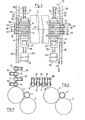
- a winding apparatus 1 (FIG. 1) comprises a first winding roller 2 and a second winding roller 3 for receiving a winding tube 4, respectively the one that is accommodated on the tube 4 Winding (not shown).
- Calender rolls 5 to 8 are arranged in front of the first winding roll 2, the calender roll 5 being referred to as the first, the calender roll 6 as the second, the calender roll 7 as the third and the calender roll 8 as the last calender roll.
- the winder is covered by a hood 9.
- the calender rolls 5 to 8 are each carried by means of two pairs of springs 10, which each consist of two spring struts 11 and 12 designed as leaf springs.
- Each pair of springs 10 is firmly connected on the one hand to a carrier 13 and on the other hand to a bearing body 14 receiving a shaft end of the calender rolls by means of screws 15.
- the carrier 13 is divided into a part 13A for receiving the screws 15 and a part 13B, which is provided with a connection surface 16 and with two threaded holes 17 for receiving screws 18 (FIG. 2).
- the carriers 13 are fastened to side walls 19 and 20 of the winding apparatus 1 in such a way that the connection surfaces 16 (FIG. 10) each abut these walls. Furthermore, the calender rolls are fastened to these walls 19 and 20 by means of these supports 13 such that the axes of rotation 21 of the calender rolls 5 to 8 each lie parallel to the rotation axis 22 of the first winding roll 2. In Figures 1 to 4 only one carrier 13 is shown per calender roll.
- calender rolls 5 to 8 in a rest position (also called a starting position), in which they have a mutual distance D of approximately 3 mm.
- a distance E provided between the last calender roll 8 and the first winding roll 2 in this rest position of the calender roll is also approximately 3 mm.
- the invention is not limited to maintaining this 3 mm for the distances D and E, larger or possibly somewhat smaller distances can also be useful for the loosening of the winding on calender rolls. In this rest position, there is a balance between the sum of the spring forces per calender roll at both ends of the calender roll and the yalander roll weight.
- D is a spring legs 11 and 12 connected by means of screws 15 fixed to the supports 13 respectively with the bearing bodies 14, have a pair of springs that is known from the strength of materials'Rechteckfeder' characteristic, that is, the deflection characteristic corresponds approximately to the deflection characteristic of the 'rectangular springs' .
- the positions of the supports 13 on the side walls 19 and 20 are shifted until the desired distance D has the desired dimension over the entire length of the calender roll.
- the cylinder 23 is supported on both sides of the calender rolls on a support 25 fastened to the corresponding wall 19 or 20 (FIG. 2, only indicated schematically in FIG. 1).
- a piston head 27 belonging to the piston 26 of the cylinder 23 bears against the leaf spring 11 relating to the calender roll 5.
- the piston head 27 is designed to be U-shaped in order to be able to rest on both sides of the screw head of the screw 15 on the leaf spring 11, as shown in FIG.
- the stop means 24 each consist of a support 28 fastened to the side wall 19 or 20 (FIG. 2, only shown schematically in FIG. 1) and an associated screw 29.
- This screw 29 serves, as can be seen from FIGS. 1 and 2, as a stop, by means of which the movement of the last calender roll 8 is stopped in such a way that said distance E does not become small in the working position of the calender rolls becomes less than approx. 0.2 mm, ie at least remains so that there is no contact between the calender roll 8 and the first winding roll 2.
- the head of the screw 15, the corresponding strut abuts the screw 29.
- the distance E can be adjusted by turning the screw 29.
- FIGS. 3 and 4 show that the use of the spring-loaded calender roller guide means shown in FIG. 1 is not restricted to the arrangements shown in FIG. 1, but in a vertical arrangement (FIG. 3) or a horizontal arrangement (FIG. 4 ) can be used.
- the calender rolls in these figures are numbered in the same order as in FIG. 1.
- FIGS. 5 to 7, in which it is shown how a cotton web 30 is brought over the calender rolls 5 to 8 and then over the first winding roll 2 and finally to the winding tube 4.
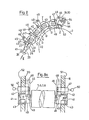
- FIGS. 8 to 11 show variants of the calender roll guide means according to the invention. The same elements therefore have the same reference numerals.
- the bearing bodies 40 are guided in a guide track 41 (FIG. 8A, only indicated schematically in FIG. 8), consisting of an upper guide rail 42 and a lower guide rail 43.
- the peripheral surface 44 of the bearing body 40 is accordingly adapted to the rails and is, for example, circular and has one for sliding between the This surface and the guide rails suitable fineness and width B (Fig. 8A).
- the guide track 41 comprises a stop bar 45 (FIG. 8A).
- the swivel arms 46 are each pivotably mounted in the side walls 19 by a bolt 48 and are pivoted clockwise until the guideway is free in order to enable the introduction of the calender rolls or their bearing bodies 40 into the guideway 41.
- the latches 47 are therefore displaceably guided in the side walls 19 and 20 in such a way that they can be displaced from a starting position in which the stop lugs 49 rest against the side wall 19 and 20 in a working position in which the stop lug 49, as in FIG 8a, lies in front of the swivel arm 46, whereby the swiveling back of the swivel arm 46 in the clockwise direction is prevented.
- the bolts 47 are further provided with a handle 50 (FIG. 8a) and with a stop (not shown). The latter serves for the correct positioning of the bolt and, in the working position of the bolt, rests on the outer surface 51 of the side wall 19, or on the outer surface 52 of the side wall 20.
- the swivel arms 46 provided on both sides of the calender roller 8 require two stops, one of which is the bolt 47, and one spring 53 each, since the calender roller 8 moves downward in the guideway clockwise.
- the spring 53 is a compression spring supported on a base 56 belonging to the side walls 19 and 20 (only indicated in FIG. 8) and urges the calender roller 8 in the guideway 41 counterclockwise into the rest position in which the swivel arm 46 on the nose 49 of the latch 47 abuts.
- the distance E has a size of approximately 3 mm.
- the calender rolls 5, 6 and 7 are in the rest position due to the force of gravity (also called gravitation), which causes them to move in the counterclockwise direction in the guideway 41, by means of the swivel arms 46 on the lugs 49, the distances between the bars 47 being chosen in this way is that in this rest position, the distances D between the calender rolls are approximately 3 mm,
- the working position of the calender rolls 5 to 8 is achieved in the manner described for FIGS. 1 and 2 by means of a cylinder 23 provided on both sides of the calender rolls. Accordingly no repetition of the elements and reference to the description section for FIGS. 1 and 2, ie the same elements are identified by the same reference numerals.
- the swivel arms 46 of the last calender roll each abut against a stop screw 54 in order to ensure that the distance E in this working position of the calender rolls is at least 0.2 mm.
- the swivel arms 46 assigned to the calender roll 8 are no longer in contact with the stop lugs 49, which also applies to the swivel arms which are assigned to the calender rolls 5, 6 and 7.
- the stop screw 54 is each connected to the side wall 19 or 20 by means of a support 55, in which a thread is provided for receiving this screw, i. H.
- a swivel arm 46, a bar 47, a spring 53 and a stop screw 54 etc. are provided on each side of the calender rolls.
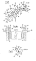
- FIGS. 9 and 9a show a further variant, similar to the variant of FIG. 8 or 8a, in which the calender rolls move in the same way due to gravity and are locked or moved in the same way by stops or springs. Accordingly, elements with the same functions have the same reference numerals as in the descriptions of the previous figures.
- the essential difference from the arrangement shown in FIGS. 8 and 8a is the guidance of the calender rolls 5 to 8 by using them pendulum arms 60 are arranged pivotally.
- the pendulum arms 60 are pivotally attached to the side walls 19 and 20 by means of bolts 48 and accommodate the bearing bodies 61 of the calender rollers 5 to 8.
- the latches 47, the locking screws 54, the compression springs 53 and the cylinders 23 have the same functions with the associated accessories as in the arrangement shown in FIGS. 8 and 8a. Accordingly, the pendulum arms 60 assigned to the calender rollers 8 rest in the rest position as a result of the spring pressure of the spring 53 on the lugs 49 of the latches 47. At the same time, the pendulum arms 60 assigned to the calender rolls 5, 6 and 7 bear against the corresponding lugs 49 of the bars 47 as a result of the gravity of the calender rolls. In this rest position, the distances D and the distance E have the previously mentioned dimension of approx. 3 mm.
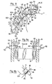
- FIG. 10 shows a further variant of the calender roll guide in which the bearing bodies 61 are received by a resilient arm 70.
- This resilient arm 70 comprises a support beam 71 (not shown) fastened to the side walls 19 and 20, a support arm 72 and a leaf spring 73 connecting the support arm 72 to the support beam 71.
- This traction cable is guided from the piston 84 through eyelets 86 provided on the pendulum arms 601 and through a compression spring 87 provided after each eyelet and each via a roller 88 fitted between the compression springs 87 and the eyelets 86.
- the end of the traction cable 85 opposite the piston 84 becomes with connected to the end of the last compression spring 87 opposite the eyelet 86.
- a driver 89 is firmly connected to the rope.
- the length of the piston stroke must be somewhat (e.g. 5 mm) longer than the sum of all distances D (analogous to Fig. 1,8,9) and the distance E, which for the sake of clarity are not entered in Figure 11.
- the spring forces of the compression springs 87 must be greater than the spring forces of the tension springs 80 so that a displacement of the calender roll from the working position to the rest position is ensured.
- FIG. 11 shows a variant of FIG. 9 and since it is only a different arrangement of the same elements, the elements have the same reference numerals as in FIG. 9.
- the calender rolls 5 to 8 by means of the pendulum arms 60 in the rest position freely suspended.
- the cylinder 23 is activated, as described with FIG. 9, until all the calender rolls abut one another and the pendulum arms 60 assigned to the calender roll 8 bear against the stop screw 54 by the described one, which is no longer shown here Bring distance E to the desired size of 0.2 mm.
- FIG. 13 shows a variant of the arrangement shown in FIG. 8, in which the guideway 41 is shifted downwards until all the calender rollers in the guideway slide downward in the same direction by means of their gravity.
- This makes it possible to dispense with the compression spring 53 shown in FIG. 8.
- Also in this figure are there are the same elements as in Fig. 8, using the same reference numerals.
- FIG. 14 The variant shown in FIG. 14 is a similar arrangement to that in FIG. 12, with the only difference that the calender rolls are not arranged in a horizontal but in a rising straight line.
- the advantage of this arrangement over that of FIG. 12 is that it is more space-saving.
- the elements are the same as in Fig. 12 respect. 9, so that the same reference numerals have also been used here.
- 15 shows a variant of the with
- FIG. 11 shows the arrangement shown, in which, on the one hand, the cable pull 82 pulls the calender rolls from the rest position into the working position and, on the other hand, that the last calender roll 8 is arranged freely suspended.
- This rearrangement has the advantage over that of FIG. 11 that the tension springs 80 can be dispensed with.
- the cable pull 82 in exactly the same way as described for FIG. 11, has a pull cable 85, the tension springs 87, the rollers 88 and the drivers 89.
Landscapes
- Engineering & Computer Science (AREA)
- Textile Engineering (AREA)
- Treatment Of Fiber Materials (AREA)
- Preliminary Treatment Of Fibers (AREA)
Applications Claiming Priority (2)
| Application Number | Priority Date | Filing Date | Title |
|---|---|---|---|
| CH5506/83 | 1983-10-10 | ||
| CH550683 | 1983-10-10 |
Publications (3)
| Publication Number | Publication Date |
|---|---|
| EP0141258A2 true EP0141258A2 (fr) | 1985-05-15 |
| EP0141258A3 EP0141258A3 (en) | 1985-06-12 |
| EP0141258B1 EP0141258B1 (fr) | 1988-01-07 |
Family
ID=4294756
Family Applications (1)
| Application Number | Title | Priority Date | Filing Date |
|---|---|---|---|
| EP84111525A Expired EP0141258B1 (fr) | 1983-10-10 | 1984-09-27 | Dispositif de bobinage pour la formation d'enroulement d'ouate |
Country Status (5)
| Country | Link |
|---|---|
| US (2) | US4637565A (fr) |
| EP (1) | EP0141258B1 (fr) |
| JP (1) | JP2568994B2 (fr) |
| DE (1) | DE3468449D1 (fr) |
| IN (1) | IN161192B (fr) |
Cited By (4)
| Publication number | Priority date | Publication date | Assignee | Title |
|---|---|---|---|---|
| EP0345558A1 (fr) * | 1988-06-06 | 1989-12-13 | Maschinenfabrik Rieter Ag | Procédé pour introduire un ruban de fibres entre les rouleaux de pression d'une machine d'enroulement de nappes de fibres textiles |
| WO1998005808A1 (fr) * | 1996-07-31 | 1998-02-12 | Maschinenfabrik Rieter Ag | Dispositif pour acheminer et comprimer une bande d'ouate |
| WO2010012111A1 (fr) * | 2008-07-31 | 2010-02-04 | Maschinenfabrik Rieter Ag | Dispositif de pression destiné à un cylindre calandreur |
| DE10323130B4 (de) * | 2002-07-25 | 2014-06-26 | Maschinenfabrik Rieter Ag | Antrieb für Kalanderwalzen |
Families Citing this family (1)
| Publication number | Priority date | Publication date | Assignee | Title |
|---|---|---|---|---|
| FI114648B (fi) * | 2003-06-18 | 2004-11-30 | Metso Paper Inc | Menetelmä ja laitteisto paperi- tai kartonkirainan kalanteroimiseksi |
Family Cites Families (24)
| Publication number | Priority date | Publication date | Assignee | Title |
|---|---|---|---|---|
| DE274246C (fr) * | ||||
| US659116A (en) * | 1900-06-21 | 1900-10-02 | Edward D Russell | Baling-press. |
| DE629355C (de) * | 1933-06-29 | 1936-04-29 | Julius Weinbrenner | Vlieswickler fuer Spinnereivorbereitungsmaschinen mit selbsttaetiger Wickelauswechselvorrichtung |
| AT147035B (de) * | 1934-03-12 | 1936-09-25 | C G Haubold Ag | Elektrischer Antrieb für Umwickelvorrichtungen mit Tragwalzen. |
| US2141315A (en) * | 1934-09-27 | 1938-12-27 | Beloit Iron Works | Unwinder and winder mechanism for paper machinery |
| CH182356A (de) * | 1935-07-30 | 1936-02-15 | Rieter Joh Jacob & Cie Ag | Vorrichtung zur Bildung von Wickeln aus Faserstoffen. |
| DE644119C (de) * | 1935-08-02 | 1937-04-24 | Rieter Joh Jacob & Cie Ag | Vorrichtung zum Aufwickeln von Faserstoffbahnen an Spinnereivorbereitungsmaschinen |
| US2138397A (en) * | 1935-10-18 | 1938-11-29 | Hunter James Machine Co | Compression roll |
| GB544009A (en) * | 1940-09-20 | 1942-03-24 | Cons Water Power & Paper Co | Improvements in a process and apparatus for coating paper |
| US2502894A (en) * | 1947-05-24 | 1950-04-04 | Whitin Machine Works | Lap winding machine |
| GB711599A (en) * | 1950-06-05 | 1954-07-07 | Rieter Joh Jacob & Cie Ag | Improvements in or relating to lap-forming apparatus |
| US3016819A (en) * | 1960-02-25 | 1962-01-16 | Mckiernan Terry Corp | Super calender with constant nip alignment |
| US3122089A (en) * | 1961-05-16 | 1964-02-25 | Anderson Clayton & Co | Rotary press and lint sampler |
| US3155029A (en) * | 1962-11-22 | 1964-11-03 | Dominion Eng Works Ltd | Calenders |
| US3154008A (en) * | 1963-02-09 | 1964-10-27 | Dominion Eng Works Ltd | Calender stack |
| US3183826A (en) * | 1963-07-11 | 1965-05-18 | Beloit Corp | Calender stack |
| US3158088A (en) * | 1963-07-11 | 1964-11-24 | Beloit Corp | Calender nip control device |
| US3270664A (en) * | 1964-06-22 | 1966-09-06 | Beloit Corp | Calender stack |
| GB1150651A (en) * | 1965-02-16 | 1969-04-30 | Tmm Research Ltd | Improvements in Textile Lap Forming and Doffing Apparatus |
| US3561359A (en) * | 1968-09-04 | 1971-02-09 | Kenneth W Cohen | Roller adjusting apparatus for a proof press |
| US3525301A (en) * | 1968-11-08 | 1970-08-25 | Beloit Corp | Calender stack |
| CH564644A5 (fr) * | 1973-04-16 | 1975-07-31 | Escher Wyss Ag | |
| JPS53131014U (fr) * | 1977-03-10 | 1978-10-18 | ||
| DE2830733C3 (de) * | 1978-07-13 | 1982-05-06 | Kleinewefers Gmbh, 4150 Krefeld | Vorrichtung zum schnellen Trennen der Walzen eines Kalanders |
-
1984
- 1984-06-15 IN IN437/MAS/84A patent/IN161192B/en unknown
- 1984-09-27 DE DE8484111525T patent/DE3468449D1/de not_active Expired
- 1984-09-27 EP EP84111525A patent/EP0141258B1/fr not_active Expired
- 1984-10-03 US US06/657,352 patent/US4637565A/en not_active Expired - Lifetime
- 1984-10-09 JP JP59210640A patent/JP2568994B2/ja not_active Expired - Fee Related
-
1986
- 1986-09-02 US US06/902,660 patent/US4718616A/en not_active Expired - Lifetime
Cited By (5)
| Publication number | Priority date | Publication date | Assignee | Title |
|---|---|---|---|---|
| EP0345558A1 (fr) * | 1988-06-06 | 1989-12-13 | Maschinenfabrik Rieter Ag | Procédé pour introduire un ruban de fibres entre les rouleaux de pression d'une machine d'enroulement de nappes de fibres textiles |
| US5001976A (en) * | 1988-06-06 | 1991-03-26 | Rieter Machine Works, Ltd. | Apparatus for drawing in a lap sheet into a lap winder |
| WO1998005808A1 (fr) * | 1996-07-31 | 1998-02-12 | Maschinenfabrik Rieter Ag | Dispositif pour acheminer et comprimer une bande d'ouate |
| DE10323130B4 (de) * | 2002-07-25 | 2014-06-26 | Maschinenfabrik Rieter Ag | Antrieb für Kalanderwalzen |
| WO2010012111A1 (fr) * | 2008-07-31 | 2010-02-04 | Maschinenfabrik Rieter Ag | Dispositif de pression destiné à un cylindre calandreur |
Also Published As
| Publication number | Publication date |
|---|---|
| US4637565A (en) | 1987-01-20 |
| JP2568994B2 (ja) | 1997-01-08 |
| EP0141258B1 (fr) | 1988-01-07 |
| IN161192B (fr) | 1987-10-17 |
| JPS6099019A (ja) | 1985-06-01 |
| EP0141258A3 (en) | 1985-06-12 |
| DE3468449D1 (en) | 1988-02-11 |
| US4718616A (en) | 1988-01-12 |
Similar Documents
| Publication | Publication Date | Title |
|---|---|---|
| DE69121069T2 (de) | Biege-Formeinrichtung von Stangen und Verfahren zum Einbringen von Biegungen der hinteren Enden von Stangen | |
| DE3875819T2 (de) | Biegepresse fuer bleche. | |
| DE3828469C2 (fr) | ||
| EP0141258B1 (fr) | Dispositif de bobinage pour la formation d'enroulement d'ouate | |
| DE971846C (de) | Hochschwenkbarer und in der Arbeitsstellung verriegelbarer Oberwalzentrag- und -belastungsarm fuer Zweiriemchenstreckwerke an Spinnmaschinen | |
| DE2810273A1 (de) | Vorrichtung zur regelung der geschwindigkeit des dorns in einem kontinuierlichen mit gehaltenem dorn arbeitenden walzwerk | |
| DE2759085A1 (de) | Fangvorrichtung fuer eine mindestens ein seil aufweisende hubvorrichtung | |
| DE2114820C3 (de) | Rahmenstickmaschine | |
| DE3025008A1 (de) | Abzugsvorrichtung fuer flachstrickmaschinen | |
| DE2557239A1 (de) | Bohrmaschine, insbesondere zum lochen mit mindestens zwei bohrwerkzeugen | |
| DE2927372A1 (de) | Stanzmaschine zum stanzen von loechern in metallbleche | |
| DE1602064B2 (de) | Walzwerk zum auswalzen eines metallrohlings | |
| DE4035000A1 (de) | Vorrichtung zum verspannen und ausbalancieren von presswerkzeugtraeger und kurbelgehaeuse einer stauchpresse | |
| DE1940414B2 (de) | Walzgerüst mit einer Einrichtung zum Walzenwechsel | |
| DE2412477A1 (de) | Streckvorrichtung fuer textilfasern | |
| DE2221842B2 (de) | Gegenzug-Schaftmaschine | |
| DE742707C (de) | Kantenleitvorrichtung fuer die Einfuehrung laufender Gewebebahnen, insbesondere in Appreturmaschinen | |
| EP0732294B1 (fr) | Machine à faire des poches pliées | |
| DE69004510T2 (de) | Streckwerk für textile Faserbänder. | |
| DE1535506B1 (de) | Steuervorrichtung fuer die Schuetzenkastenbewegung an mit einer Mustersteuervorrichtung versehenen Webmaschinen | |
| DE1477223A1 (de) | Gewindeschneidmaschine | |
| EP0036004B1 (fr) | Metier a filer en gros | |
| DE2810272A1 (de) | Vorrichtung zur sperrung und entsperrung des stangentraegerschlittens einer walz- und perforierpresse | |
| DE1291312B (de) | Walzgeruest mit in einer gemeinsamen Ebene angeordneten Horizontalwalzen | |
| DE229587C (fr) |
Legal Events
| Date | Code | Title | Description |
|---|---|---|---|
| PUAI | Public reference made under article 153(3) epc to a published international application that has entered the european phase |
Free format text: ORIGINAL CODE: 0009012 |
|
| PUAL | Search report despatched |
Free format text: ORIGINAL CODE: 0009013 |
|
| AK | Designated contracting states |
Designated state(s): BE CH DE FR GB IT LI |
|
| 17P | Request for examination filed |
Effective date: 19850327 |
|
| AK | Designated contracting states |
Designated state(s): BE CH DE FR GB IT LI |
|
| 17Q | First examination report despatched |
Effective date: 19860428 |
|
| GRAA | (expected) grant |
Free format text: ORIGINAL CODE: 0009210 |
|
| AK | Designated contracting states |
Kind code of ref document: B1 Designated state(s): BE CH DE FR GB IT LI |
|
| ITF | It: translation for a ep patent filed | ||
| REF | Corresponds to: |
Ref document number: 3468449 Country of ref document: DE Date of ref document: 19880211 |
|
| GBT | Gb: translation of ep patent filed (gb section 77(6)(a)/1977) | ||
| ET | Fr: translation filed | ||
| PLBE | No opposition filed within time limit |
Free format text: ORIGINAL CODE: 0009261 |
|
| STAA | Information on the status of an ep patent application or granted ep patent |
Free format text: STATUS: NO OPPOSITION FILED WITHIN TIME LIMIT |
|
| 26N | No opposition filed | ||
| PGFP | Annual fee paid to national office [announced via postgrant information from national office to epo] |
Ref country code: GB Payment date: 19910808 Year of fee payment: 8 |
|
| PGFP | Annual fee paid to national office [announced via postgrant information from national office to epo] |
Ref country code: FR Payment date: 19910814 Year of fee payment: 8 |
|
| PGFP | Annual fee paid to national office [announced via postgrant information from national office to epo] |
Ref country code: BE Payment date: 19910821 Year of fee payment: 8 |
|
| PG25 | Lapsed in a contracting state [announced via postgrant information from national office to epo] |
Ref country code: GB Effective date: 19920927 |
|
| PG25 | Lapsed in a contracting state [announced via postgrant information from national office to epo] |
Ref country code: BE Effective date: 19920930 |
|
| BERE | Be: lapsed |
Owner name: MASCHINENFABRIK RIETER A.G. Effective date: 19920930 |
|
| GBPC | Gb: european patent ceased through non-payment of renewal fee |
Effective date: 19920927 |
|
| PG25 | Lapsed in a contracting state [announced via postgrant information from national office to epo] |
Ref country code: FR Effective date: 19930528 |
|
| REG | Reference to a national code |
Ref country code: FR Ref legal event code: ST |
|
| ITTA | It: last paid annual fee | ||
| PGFP | Annual fee paid to national office [announced via postgrant information from national office to epo] |
Ref country code: CH Payment date: 19980907 Year of fee payment: 15 |
|
| PG25 | Lapsed in a contracting state [announced via postgrant information from national office to epo] |
Ref country code: LI Free format text: LAPSE BECAUSE OF NON-PAYMENT OF DUE FEES Effective date: 19990930 Ref country code: CH Free format text: LAPSE BECAUSE OF NON-PAYMENT OF DUE FEES Effective date: 19990930 |
|
| REG | Reference to a national code |
Ref country code: CH Ref legal event code: PL |
|
| PGFP | Annual fee paid to national office [announced via postgrant information from national office to epo] |
Ref country code: DE Payment date: 20020827 Year of fee payment: 19 |
|
| PG25 | Lapsed in a contracting state [announced via postgrant information from national office to epo] |
Ref country code: DE Free format text: LAPSE BECAUSE OF NON-PAYMENT OF DUE FEES Effective date: 20040401 |