EP0141259A1 - Flüssigkeitschromatographie - Google Patents
Flüssigkeitschromatographie Download PDFInfo
- Publication number
- EP0141259A1 EP0141259A1 EP84111529A EP84111529A EP0141259A1 EP 0141259 A1 EP0141259 A1 EP 0141259A1 EP 84111529 A EP84111529 A EP 84111529A EP 84111529 A EP84111529 A EP 84111529A EP 0141259 A1 EP0141259 A1 EP 0141259A1
- Authority
- EP
- European Patent Office
- Prior art keywords
- mobile phase
- carrier fluid
- electrochemically
- electrodes
- electrode
- Prior art date
- Legal status (The legal status is an assumption and is not a legal conclusion. Google has not performed a legal analysis and makes no representation as to the accuracy of the status listed.)
- Granted
Links
- 238000004811 liquid chromatography Methods 0.000 title claims abstract description 21
- 238000004587 chromatography analysis Methods 0.000 claims abstract description 31
- 239000000523 sample Substances 0.000 claims abstract description 27
- 238000000034 method Methods 0.000 claims abstract description 19
- 239000012530 fluid Substances 0.000 claims abstract description 15
- 239000000463 material Substances 0.000 claims abstract description 15
- 239000011263 electroactive material Substances 0.000 claims abstract description 7
- 230000008859 change Effects 0.000 claims abstract description 5
- 238000012360 testing method Methods 0.000 claims description 16
- 238000012216 screening Methods 0.000 claims description 5
- 230000001590 oxidative effect Effects 0.000 claims 2
- 238000000835 electrochemical detection Methods 0.000 description 13
- 239000012071 phase Substances 0.000 description 13
- 241000894007 species Species 0.000 description 12
- 238000002347 injection Methods 0.000 description 9
- 239000007924 injection Substances 0.000 description 9
- 238000000926 separation method Methods 0.000 description 9
- OKTJSMMVPCPJKN-UHFFFAOYSA-N Carbon Chemical compound [C] OKTJSMMVPCPJKN-UHFFFAOYSA-N 0.000 description 8
- KDLHZDBZIXYQEI-UHFFFAOYSA-N Palladium Chemical compound [Pd] KDLHZDBZIXYQEI-UHFFFAOYSA-N 0.000 description 7
- 238000001514 detection method Methods 0.000 description 7
- 230000008569 process Effects 0.000 description 7
- 239000000243 solution Substances 0.000 description 7
- OKKJLVBELUTLKV-UHFFFAOYSA-N Methanol Chemical compound OC OKKJLVBELUTLKV-UHFFFAOYSA-N 0.000 description 6
- 229910002804 graphite Inorganic materials 0.000 description 5
- 239000010439 graphite Substances 0.000 description 5
- RZVAJINKPMORJF-UHFFFAOYSA-N Acetaminophen Chemical compound CC(=O)NC1=CC=C(O)C=C1 RZVAJINKPMORJF-UHFFFAOYSA-N 0.000 description 4
- 229910052799 carbon Inorganic materials 0.000 description 4
- 239000011262 electrochemically active material Substances 0.000 description 4
- 239000003456 ion exchange resin Substances 0.000 description 4
- 229920003303 ion-exchange polymer Polymers 0.000 description 4
- 230000035945 sensitivity Effects 0.000 description 4
- 238000013375 chromatographic separation Methods 0.000 description 3
- 239000007788 liquid Substances 0.000 description 3
- QSHDDOUJBYECFT-UHFFFAOYSA-N mercury Chemical compound [Hg] QSHDDOUJBYECFT-UHFFFAOYSA-N 0.000 description 3
- 229910052753 mercury Inorganic materials 0.000 description 3
- 229910052751 metal Inorganic materials 0.000 description 3
- 239000002184 metal Substances 0.000 description 3
- 238000012856 packing Methods 0.000 description 3
- 229910052763 palladium Inorganic materials 0.000 description 3
- 239000007787 solid Substances 0.000 description 3
- 239000007790 solid phase Substances 0.000 description 3
- 238000011144 upstream manufacturing Methods 0.000 description 3
- NBIIXXVUZAFLBC-UHFFFAOYSA-N Phosphoric acid Chemical compound OP(O)(O)=O NBIIXXVUZAFLBC-UHFFFAOYSA-N 0.000 description 2
- 239000000356 contaminant Substances 0.000 description 2
- 239000012777 electrically insulating material Substances 0.000 description 2
- 239000003822 epoxy resin Substances 0.000 description 2
- 239000011159 matrix material Substances 0.000 description 2
- 238000005259 measurement Methods 0.000 description 2
- 238000012986 modification Methods 0.000 description 2
- 230000004048 modification Effects 0.000 description 2
- 230000003287 optical effect Effects 0.000 description 2
- 229910003445 palladium oxide Inorganic materials 0.000 description 2
- JQPTYAILLJKUCY-UHFFFAOYSA-N palladium(ii) oxide Chemical compound [O-2].[Pd+2] JQPTYAILLJKUCY-UHFFFAOYSA-N 0.000 description 2
- 229960005489 paracetamol Drugs 0.000 description 2
- 229920000647 polyepoxide Polymers 0.000 description 2
- -1 polypropylene Polymers 0.000 description 2
- 239000000843 powder Substances 0.000 description 2
- 239000012488 sample solution Substances 0.000 description 2
- 238000012546 transfer Methods 0.000 description 2
- XLYOFNOQVPJJNP-UHFFFAOYSA-N water Substances O XLYOFNOQVPJJNP-UHFFFAOYSA-N 0.000 description 2
- 239000004215 Carbon black (E152) Substances 0.000 description 1
- 229920001780 ECTFE Polymers 0.000 description 1
- 239000004593 Epoxy Substances 0.000 description 1
- 229920004459 Kel-F® PCTFE Polymers 0.000 description 1
- 239000004743 Polypropylene Substances 0.000 description 1
- 241000982035 Sparattosyce Species 0.000 description 1
- 229920006362 Teflon® Polymers 0.000 description 1
- 238000010521 absorption reaction Methods 0.000 description 1
- 239000002253 acid Substances 0.000 description 1
- 229910000147 aluminium phosphate Inorganic materials 0.000 description 1
- 238000004458 analytical method Methods 0.000 description 1
- 238000007630 basic procedure Methods 0.000 description 1
- 239000011324 bead Substances 0.000 description 1
- 238000010276 construction Methods 0.000 description 1
- 238000005553 drilling Methods 0.000 description 1
- 230000000694 effects Effects 0.000 description 1
- 238000002848 electrochemical method Methods 0.000 description 1
- 238000005538 encapsulation Methods 0.000 description 1
- 230000007613 environmental effect Effects 0.000 description 1
- 229930195733 hydrocarbon Natural products 0.000 description 1
- 239000011810 insulating material Substances 0.000 description 1
- 238000005342 ion exchange Methods 0.000 description 1
- 230000014759 maintenance of location Effects 0.000 description 1
- 238000012544 monitoring process Methods 0.000 description 1
- 229920001155 polypropylene Polymers 0.000 description 1
- 229920000915 polyvinyl chloride Polymers 0.000 description 1
- 239000004800 polyvinyl chloride Substances 0.000 description 1
- 239000011148 porous material Substances 0.000 description 1
- 238000004382 potting Methods 0.000 description 1
- 239000011347 resin Substances 0.000 description 1
- 229920005989 resin Polymers 0.000 description 1
- 238000004366 reverse phase liquid chromatography Methods 0.000 description 1
- 150000003839 salts Chemical class 0.000 description 1
- 239000002904 solvent Substances 0.000 description 1
- 229910001220 stainless steel Inorganic materials 0.000 description 1
- 239000010935 stainless steel Substances 0.000 description 1
- 239000000126 substance Substances 0.000 description 1
- 230000001629 suppression Effects 0.000 description 1
- 239000002699 waste material Substances 0.000 description 1
Images


Classifications
-
- G—PHYSICS
- G01—MEASURING; TESTING
- G01N—INVESTIGATING OR ANALYSING MATERIALS BY DETERMINING THEIR CHEMICAL OR PHYSICAL PROPERTIES
- G01N27/00—Investigating or analysing materials by the use of electric, electrochemical, or magnetic means
- G01N27/26—Investigating or analysing materials by the use of electric, electrochemical, or magnetic means by investigating electrochemical variables; by using electrolysis or electrophoresis
- G01N27/403—Cells and electrode assemblies
- G01N27/404—Cells with anode, cathode and cell electrolyte on the same side of a permeable membrane which separates them from the sample fluid, e.g. Clark-type oxygen sensors
- G01N27/4045—Cells with anode, cathode and cell electrolyte on the same side of a permeable membrane which separates them from the sample fluid, e.g. Clark-type oxygen sensors for gases other than oxygen
-
- G—PHYSICS
- G01—MEASURING; TESTING
- G01N—INVESTIGATING OR ANALYSING MATERIALS BY DETERMINING THEIR CHEMICAL OR PHYSICAL PROPERTIES
- G01N30/00—Investigating or analysing materials by separation into components using adsorption, absorption or similar phenomena or using ion-exchange, e.g. chromatography or field flow fractionation
- G01N30/02—Column chromatography
- G01N30/04—Preparation or injection of sample to be analysed
- G01N30/06—Preparation
- G01N30/14—Preparation by elimination of some components
-
- G—PHYSICS
- G01—MEASURING; TESTING
- G01N—INVESTIGATING OR ANALYSING MATERIALS BY DETERMINING THEIR CHEMICAL OR PHYSICAL PROPERTIES
- G01N30/00—Investigating or analysing materials by separation into components using adsorption, absorption or similar phenomena or using ion-exchange, e.g. chromatography or field flow fractionation
- G01N30/02—Column chromatography
- G01N30/26—Conditioning of the fluid carrier; Flow patterns
- G01N30/28—Control of physical parameters of the fluid carrier
- G01N30/34—Control of physical parameters of the fluid carrier of fluid composition, e.g. gradient
-
- G—PHYSICS
- G01—MEASURING; TESTING
- G01N—INVESTIGATING OR ANALYSING MATERIALS BY DETERMINING THEIR CHEMICAL OR PHYSICAL PROPERTIES
- G01N30/00—Investigating or analysing materials by separation into components using adsorption, absorption or similar phenomena or using ion-exchange, e.g. chromatography or field flow fractionation
- G01N30/02—Column chromatography
- G01N30/62—Detectors specially adapted therefor
- G01N30/64—Electrical detectors
-
- G—PHYSICS
- G01—MEASURING; TESTING
- G01N—INVESTIGATING OR ANALYSING MATERIALS BY DETERMINING THEIR CHEMICAL OR PHYSICAL PROPERTIES
- G01N30/00—Investigating or analysing materials by separation into components using adsorption, absorption or similar phenomena or using ion-exchange, e.g. chromatography or field flow fractionation
- G01N30/02—Column chromatography
Definitions
- the present invention relates to improvements in liquid chromatography, and in particular to improved methods for analyzing sample materials using chromatographic techniques.
- Liquid chromatography is a well-known analytical technique in which a sample material is separated into its component species by dissolving the sample material in a carrier fluid to form a mobile phase which is then passed continuously through a solid phase.
- the solid phase comprises a bed of ion exchange resins in powder or bead form, arranged in a stack or column.
- the various species contained in the sample material separate as a result of their different values of attraction for the various ion exchange resins in the bed to produce a so-called eluant solution which is then passed through a detection device.
- detection devices for liquid chromatography have been based on measurements of optical phenomena such as differences in indices of refraction or ultraviolet absorption of the various species in the chromatographic eluant.
- chromatographic separation generally can be achieved at a level of selectivity that is substantially more precise than the level of sensitivity of detection achieveable using classical optically based detection devices.
- detection devices based on electrochemical measurements have been proposed for use in connection with liquid chromatography separations.
- One such proposed electrochemical detection device employs a hanging drop mercury electrode suspended in the eluant solution.
- Patent 3706381 detectors employing hanging drop mercury electrodes have not proved to be entirely satisfactory due to the considerable noise associated with the dropping mercury. It has also been proposed to employ solid electrodes for directly measuring species in an eluant solution.
- One such proposed device employs a test electrode in the form of a solid graphite button or a carbon or graphite paste flat plate for contacting the eluant stream from a liquid chromatography column.
- electrochemical detection devices of this type generally are able to achieve sensitivity of 100 picograms at best, and may suffer from decay of sensitivity.
- electrochemical detection devices employing carbon or graphite paste electrodes may function well for many applications of reverse-phase chromatography
- problems can develop when nonaqueous solvents are used due to the combination of a high volume flow rate with the mechanical instability of the carbon paste matrix.
- the relatively high electrical resistance of nonaqueous mobile phases can limit the linear range (on the high end) of thin layer amperometric detectors due to ohmic potential losses along the thin-layer channel.
- Another disadvantage of known electrochemical detection devices is that such devices generally rely on measuring changes in charge transfer phenomena; thus known electrochemical detection devices generally are limited in use to detecting only those materials capable of undergoing charge transfer.
- an electrochemical detection apparatus of extreme sensitivity which essentially comprises a flow cell having at least one active testing electrode at least one reference electrode, and at least one counter electrode.
- Each electrode comprises a liquid impervious solid body having a bore extending therethrough with the electrode active surface located in the bore.
- the electrodes are arranged in a stack, electrically insulated from one another with their respective bores aligned so as to define a flow channel through which liquid to be detected can be passed.
- the flow cell includes a holder assembly defining a flow path and having an inlet for directing a stream of solution into the cell and an outlet for directing solution from the cell.
- the flow cell is encapsulated within an impact resistant, chemically resistant, electrically insulating material.
- Various electrochemical responses are achieved by varying the construction, number and arrangement of electrodes in the stack, and the potentials applied to the electrodes. While the electrochemical detection apparatus of my aforesaid Application EP-A-0033188 overcomes many of the aforesaid problems of the prior art, problems still subsist due to interference signals from electrochemically active materials in the mobile phase, and/or insufficient separation of species in the chromatography column.
- U.S. Patent 3,997,836 discloses a flow cell encapsulated within a high impact resistant, chemically resistant, chemically insulating material, with fittings extending in part beyond the encapsulation.
- the flow cell of said U.S. Patent 3,997,836 is disposed downstream of a chromatography column.
- the flow cell suffers from similar problems due to interference signals from electrochemically active materials in the mobile phase, and/or insufficient separation of species in the chromatography column.
- Yet other forms of electrochemical detection apparatus for use in chromatographic separations are disclosed in U.S. Patent Nos. 3,694,335 and 3,706,381. These systems also suffer from problems due to interference from electrochemically active materials in the mobile phase and/or separation of species in the chromatography column.
- the apparatus includes a pair of diffuser or ion-exchange columns having a flow-through conductivity cell located in-line between the columns.
- a second conductivity cell is located downstream of the second column.
- a method of chromatographically analyzing a sample material wherein a sample is dissolved in a carrier fluid to form a mobile phase which then is passed through a chromatography column, characterized by electrochemically screening the carrier fluid so as to selectively remove electroactive materials therein prior to injecting the sample material into the carrier fluid.
- the invention also provides a method of analyzing a sample material by liquid chromatography wherein said sample is dissolved in a carrier fluid to form a mobile phase which then is passed through a chromatography column, characterized by electrochemically treating the mobile phase prior to passing said mobile phase through the chromatography column thereby to change chromatographic characteristics of selective materials therein.
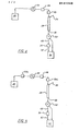
- FIG. 1 there is illustrated a liquid chromatography apparatus for use in accordance with the process of the present invention.
- the illustrated liquid chromatography apparatus which is made in accordance with my copending (parent) application Serial No. EPO 82301069.6 includes a mobile phase reservoir 20 coupled through a constant volume pump means 22, an electrochemical flow cell 23 (as will be described in detail hereinafter), and an injection valve 24 and sample inlet 26 to the top of a liquid chromatography column indicated generally at 28.
- sample materials to be tested are introduced into the chromatography apparatus either by direct injection of microliter amounts of sample material into the chromatography column 28, e.g.
- Chromatography column 28 is packed with selected ion exchange resins in bed or powder form. The selection of the mobile phase, and the selection and packing order of the ion exchange resins will depend on the particular separations desired and can readily be determined by one skilled in the art and thus will not be further described herein.
- the base of chromatography column 28 is coupled via an outlet 30 to a splitter valve 32 which divides the eluant from the chromatography column 28 between a sample collection vessel or waste container 34 and a detection device indicated generally at 36.
- the illustrated chromatography apparatus (less electrochemical flow cell 23) is conventional and may be of the type described by P.H. Freeman and W.L. Zielinski in U.S. Bureau of Standards Technological Note Number 589, Page 1 (July 1980 to June 1979).
- electrochemical flow cell 23 indicated generally at 36, comprises a hollow cylindrical body 38 formed of a rigid, liquid impervious, electrically insulating, chemically inert material such as a synthetic polymeric material, e.g. an unplasticised polyvinyl chloride, polypropylene, a polytetrafluoroethylene fluorocarbon resin such as Teflon ® Kel-F®, Halar®, Fluoron @ or other commercially available polymeric material.
- Cylindrical body 38 defines an elongate cylindrical flow path 40 in which are located the individual electrodes of electrochemical flow cell 23, as will be described in detail hereinafter.
- a plurality of radial drillings or bores 42 are formed through the side wall of body 38 and provides entry for electrical connections to the electrodes located within flow path 40.
- electrochemical flow cell 23 has at least one working electrode, at least one reference electrode and at least one counter electrode.
- a preferred form of cell 23 shown in Figs. 2 and 3 comprises five electrically discrete electrode elements arranged as follows: -- an active testing electrode 44, two counter electrodes 46 and 48, and two reference electrodes 50 and-52.
- Active testing electrode 44 comprises a short cylindrical body or frit formed of an electrically conductive, chemical inert, porous electrode base material such as a porous metal or graphite. By nature of its porosity testing electrode 44 has a relatively high active surface area.
- Counter electrodes 46 and 48 also may comprise frits of similar porous electrode base material, but preferably counter electrodes 46 and 48 comprise inert metal terminals such as one wire or a plurality of palladium or platinium wires.
- Reference electrodes 50 and 52 comprise inert metal terminals such as one wire or a plurality of palladium, palladium oxide or platinium wires.
- reference electrodes 50 and 52 are closely spaced from and equidistant from active testing electrode 44, while counter electrodes 46 and 48 are located further away from testing electrode 44.
- Active testing electrode 44, counter electrodes 46 and 48, and reference electrodes 50 and 52 are connected via palladium or platinium wires 54, 56 and 58 to sources of controlled testing potential, counter potential and reference potential, respectively.
- Completing flow cell 23 are a pair of rigid, high pressure resistent terminations such as stainless steel tubing segments 60 and 62. The latter are jam fitted into the respective ends of body 38 flow path 40, and body 38 in its entirety and tubing segments 60 and 62 in part, are potted or encapsulated within a high impact resistant, chemically resistant, electrically insulating material such as an epoxy resin indicated generally 64. As seen in Fig. 2, tubing segments 60 and 62 extend beyond the epoxy potting in part to permit connection of cell 23 in line in the chromatography system. Alternatively, fittings may be molded integrally with the epoxy resin body 64, for example, as internally threaded fittings in place of tubing segments 60 and 62. Cell 23 may be placed at various points in a chromatography system as will be described in detail hereinbelow.
- Fig. 1 shows the placement of a flow cell 23 upstream of injection valve 24.
- cell 23 With cell 23 located at this position in a chromatography system, it can, through appropriate application of electrical potentials to the cell, act as a screen to remove selected electrochemically active materials in the mobile phase used to elute column 28, thus reducing background level of contaminants reaching the column and eluting from the column. This in turn may reduce background signals and thus enhance operation of the downstream detector device 36 and/or permit the use of certain mobile phase combinations with UV or fluorescent detectors which ordinarily could not be used with such detectors. Removal of certain contaminants also may increase column life.
- Fig. 4 illustrates the placement of flow cell 23 immediately downstream of injection valve 24.
- cell 23 located at this position in a chromatography system, one can, through appropriate application of electrical potentials to the cell, electrochemically modify (i.e. oxidize or reduce) selected materials injected into the column, thereby changing the material's chromatographic characteristics whereby to permit chromatographic separations that might otherwise be impossible.
- Fig. 5 illustrates the placement of two flow cells 23a, 23b respectively, made in accordance with the present invention, in a chromatography system, upstream and downstream of injection valve 24. This embodiment provides both screening and materials modification.
- An electrochemical flow cell 23 made in accordance with Figs. 2 and 3 was used.
- the cell comprised one active testing electrode 44 formed of graphite with 0.8pm pore size 50% porosity, two palladium oxide wire reference electrodes 50 and 52 and two palladium wire counter electrodes 46 and 48.
- the flow cell 23 was located in line upstream of injection valve 24, i.e. as shown in Fig. 1.
- the basic procedure was to dissolve small amounts of Acetaminophen in methyl alcohol/phosphoric acid/water matrix (30% methyl alcohol, 70% water, 0.01% H 3 P0 4 ) to form an eluant solution.
- the sample solution was then introduced into a Model 848 (TM) liquid chromatography system (available from E. I. DuPont de Nemours and Co.).
- TM Model 848
- the chromatography column was packed with a Zorbax- C-8 (TM) column packing from E. I. DuPont de Nemours and Co. (The manufacturer describes the packing as comprising an eight-carbon hydrocarbon on an inert carrier).
- Flow rate through the chromatography column was 1.5 ml/min, with an inlet pressure of 220.6304 x 10 6 dynes/cm 2 .
- the eluant from the chromatography column was run through an electrochemical detection cell (Model No. 5100(TM) available from Environmental Sciences Associates, Inc.).
- the electrical signal outputs from the electrochemical detection cell were recorded on an automatic recorder and shown in Fig. 6a with the flow cell 23 turned on (+0.9V.) and off. As can be seen in Fig. 6a flow cell 23 provides substantial suppression of background signals.
- Example I was repeated with the following change: -Flow cell 23 was located between injection valve 24 and chromatography column 28.
- the electrical signal outputs from the electrochemical detection cell 36 were recorded as before on an automatic recorder and shown in Fig. 6b and Fig. 6c with the flow cell 23 turned on (+0.8V.) and off.
- flow cell 23 provides a substantial shift in retention time for the oxidized form of Acetaminophen.
- Additional cells set at other potentials may be included in line to further suppress background and/or to further modify other selected materials to change their chromatographic characteristics.
- electrochemical flow cell 23 offers a number of advantages in liquid chromatography. Furthermore, electrochemical flow 23 is not limited to use as a flow cell in liquid chromatography separations, but may also be advantageously employed for monitoring or directly measuring a variety of sample solutions, for example, of industrial, enviromental, geophysical and biomedical interest. In this regard it should be noted that cell 23 is ideally suited for high pressure applications. Still other features, modifications, advantages and objects will be obvious to one skilled in the art.
Landscapes
- Chemical & Material Sciences (AREA)
- Life Sciences & Earth Sciences (AREA)
- Health & Medical Sciences (AREA)
- Physics & Mathematics (AREA)
- Analytical Chemistry (AREA)
- Biochemistry (AREA)
- General Health & Medical Sciences (AREA)
- General Physics & Mathematics (AREA)
- Immunology (AREA)
- Pathology (AREA)
- Chemical Kinetics & Catalysis (AREA)
- Electrochemistry (AREA)
- Molecular Biology (AREA)
- Treatment Of Liquids With Adsorbents In General (AREA)
Priority Applications (2)
| Application Number | Priority Date | Filing Date | Title |
|---|---|---|---|
| EP84111529A EP0141259B1 (de) | 1981-03-09 | 1982-03-03 | Flüssigkeitschromatographie |
| AT84111529T ATE43915T1 (de) | 1981-03-09 | 1984-09-27 | Fluessigkeitschromatographie. |
Applications Claiming Priority (3)
| Application Number | Priority Date | Filing Date | Title |
|---|---|---|---|
| US241945 | 1981-03-09 | ||
| US06/241,945 US4413505A (en) | 1981-03-09 | 1981-03-09 | Electrochemical flow cell, particularly use with liquid chromatography |
| EP84111529A EP0141259B1 (de) | 1981-03-09 | 1982-03-03 | Flüssigkeitschromatographie |
Related Parent Applications (1)
| Application Number | Title | Priority Date | Filing Date |
|---|---|---|---|
| EP82301069.9 Division | 1982-03-03 |
Publications (2)
| Publication Number | Publication Date |
|---|---|
| EP0141259A1 true EP0141259A1 (de) | 1985-05-15 |
| EP0141259B1 EP0141259B1 (de) | 1989-06-07 |
Family
ID=26092230
Family Applications (1)
| Application Number | Title | Priority Date | Filing Date |
|---|---|---|---|
| EP84111529A Expired EP0141259B1 (de) | 1981-03-09 | 1982-03-03 | Flüssigkeitschromatographie |
Country Status (2)
| Country | Link |
|---|---|
| EP (1) | EP0141259B1 (de) |
| AT (1) | ATE43915T1 (de) |
Cited By (4)
| Publication number | Priority date | Publication date | Assignee | Title |
|---|---|---|---|---|
| FR2583879A1 (fr) * | 1985-06-20 | 1986-12-26 | Chromatografield | Cellule de mesure d'un appareil de chromatographie en phase liquide |
| FR2583880A1 (fr) * | 1985-06-20 | 1986-12-26 | Chromatografield | Cellule de mesure electrochimique d'un appareil de chromatographie en phase liquide et joints equipant celle-ci |
| WO1992002815A3 (en) * | 1990-08-10 | 1992-04-30 | Perseptive Biosystems Inc | Quantitative analysis and monitoring of protein structure by subtractive chromatography |
| EP1984728A4 (de) * | 2006-01-26 | 2012-04-18 | Eksigent Technologies Llc | Mikroskalige elektrochemische zelle und verfahren mit der zelle |
Citations (4)
| Publication number | Priority date | Publication date | Assignee | Title |
|---|---|---|---|---|
| FR1445835A (fr) * | 1964-08-14 | 1966-07-15 | Technicon Chromatography Corp | Procédé et appareil pour analyse chromatographique |
| US3649498A (en) * | 1965-10-06 | 1972-03-14 | Victor Pretorius | Detection in chromatography |
| US3690835A (en) * | 1969-03-06 | 1972-09-12 | California Inst Of Techn | Method and apparatus for analyzing gaseous chromatographic effluents |
| US3706381A (en) * | 1970-05-19 | 1972-12-19 | Pye Ltd | Chromatographic apparatus |
-
1982
- 1982-03-03 EP EP84111529A patent/EP0141259B1/de not_active Expired
-
1984
- 1984-09-27 AT AT84111529T patent/ATE43915T1/de not_active IP Right Cessation
Patent Citations (4)
| Publication number | Priority date | Publication date | Assignee | Title |
|---|---|---|---|---|
| FR1445835A (fr) * | 1964-08-14 | 1966-07-15 | Technicon Chromatography Corp | Procédé et appareil pour analyse chromatographique |
| US3649498A (en) * | 1965-10-06 | 1972-03-14 | Victor Pretorius | Detection in chromatography |
| US3690835A (en) * | 1969-03-06 | 1972-09-12 | California Inst Of Techn | Method and apparatus for analyzing gaseous chromatographic effluents |
| US3706381A (en) * | 1970-05-19 | 1972-12-19 | Pye Ltd | Chromatographic apparatus |
Cited By (5)
| Publication number | Priority date | Publication date | Assignee | Title |
|---|---|---|---|---|
| FR2583879A1 (fr) * | 1985-06-20 | 1986-12-26 | Chromatografield | Cellule de mesure d'un appareil de chromatographie en phase liquide |
| FR2583880A1 (fr) * | 1985-06-20 | 1986-12-26 | Chromatografield | Cellule de mesure electrochimique d'un appareil de chromatographie en phase liquide et joints equipant celle-ci |
| WO1992002815A3 (en) * | 1990-08-10 | 1992-04-30 | Perseptive Biosystems Inc | Quantitative analysis and monitoring of protein structure by subtractive chromatography |
| AU654503B2 (en) * | 1990-08-10 | 1994-11-10 | Perseptive Biosystems, Inc. | Quantitative analysis and monitoring of protein structure by subtractive chromatography |
| EP1984728A4 (de) * | 2006-01-26 | 2012-04-18 | Eksigent Technologies Llc | Mikroskalige elektrochemische zelle und verfahren mit der zelle |
Also Published As
| Publication number | Publication date |
|---|---|
| ATE43915T1 (de) | 1989-06-15 |
| EP0141259B1 (de) | 1989-06-07 |
Similar Documents
| Publication | Publication Date | Title |
|---|---|---|
| EP0060082B1 (de) | Elektrochemische Durchflusszelle für die Flüssigkeitschromatographie | |
| US4404065A (en) | Electrochemical detection system and method of analysis | |
| Knecht et al. | On-column electrochemical detector with a single graphite fiber electrode for open-tubular liquid chromatography | |
| US5192416A (en) | Method and apparatus for batch injection analysis | |
| EP0122009B1 (de) | Vorrichtung zur elektrochemischen Detektion | |
| US4552013A (en) | Electrochemical system | |
| WO1992018857A1 (en) | Method and apparatus for batch injection analysis and trace metal testing | |
| EP0114102B1 (de) | Vorrichtung zur elektronischen Nachweisung und zum coulometrischen Titrieren | |
| US4861555A (en) | Apparatus for chromatographic analysis of ionic species | |
| US3649498A (en) | Detection in chromatography | |
| Pihlar et al. | Amperometric determination of cyanide by use of a flow-through electrode | |
| Ridlen et al. | Determination of erythromycin in urine and plasma using microbore liquid chromatography with tris (2, 2′-bipyridyl) ruthenium (II) electrogenerated chemiluminescence detection | |
| US4497199A (en) | Liquid chromatography | |
| EP0141259B1 (de) | Flüssigkeitschromatographie | |
| US4576706A (en) | Flowthrough-type electrolytic cell | |
| Parthasarathy et al. | On‐Line Coupling of Flow Through Voltammetric Microcell to Hollow Fiber Permeation Liquid Membrane Device for Subnanomolar Trace Metal Speciation Measurements | |
| US3759816A (en) | Detection in chromatography | |
| US3997836A (en) | Detector for chromatographs | |
| Jandik et al. | Electrochemical detectors for ion chromatographic analysis: A critical review | |
| Hackman et al. | Differential pulse amperometric detection of drugs in plasma using a dropping mercury electrode as a high-performance liquid chromatographic detector | |
| Turner et al. | Automated electrochemical stripping of copper, lead, and cadmium in seawater | |
| US5368706A (en) | Amperometric detection cell | |
| Wang et al. | Ion transfer across water/solidified nitrobenzene interface as amperometric flow detector | |
| Macka et al. | Capillary electrophoresis with end‐capillary potentiometric detection using a copper electrode | |
| Wang et al. | A porous-jet flow-through electrode |
Legal Events
| Date | Code | Title | Description |
|---|---|---|---|
| PUAI | Public reference made under article 153(3) epc to a published international application that has entered the european phase |
Free format text: ORIGINAL CODE: 0009012 |
|
| AC | Divisional application: reference to earlier application |
Ref document number: 60082 Country of ref document: EP |
|
| AK | Designated contracting states |
Designated state(s): AT BE CH DE FR GB IT LI LU NL SE |
|
| 17P | Request for examination filed |
Effective date: 19851104 |
|
| 17Q | First examination report despatched |
Effective date: 19870728 |
|
| GRAA | (expected) grant |
Free format text: ORIGINAL CODE: 0009210 |
|
| AC | Divisional application: reference to earlier application |
Ref document number: 60082 Country of ref document: EP |
|
| AK | Designated contracting states |
Kind code of ref document: B1 Designated state(s): AT BE CH DE FR GB IT LI LU NL SE |
|
| PG25 | Lapsed in a contracting state [announced via postgrant information from national office to epo] |
Ref country code: SE Effective date: 19890607 Ref country code: BE Effective date: 19890607 Ref country code: AT Effective date: 19890607 |
|
| REF | Corresponds to: |
Ref document number: 43915 Country of ref document: AT Date of ref document: 19890615 Kind code of ref document: T |
|
| ITF | It: translation for a ep patent filed | ||
| REF | Corresponds to: |
Ref document number: 3279758 Country of ref document: DE Date of ref document: 19890713 |
|
| ET | Fr: translation filed | ||
| REG | Reference to a national code |
Ref country code: CH Ref legal event code: PFA Free format text: ESA, INC. |
|
| ITTA | It: last paid annual fee | ||
| PG25 | Lapsed in a contracting state [announced via postgrant information from national office to epo] |
Ref country code: LU Free format text: LAPSE BECAUSE OF NON-PAYMENT OF DUE FEES Effective date: 19900331 |
|
| NLT1 | Nl: modifications of names registered in virtue of documents presented to the patent office pursuant to art. 16 a, paragraph 1 |
Owner name: ESA, INC. TE BEDFORD, MASSACHUSETTS, VER. ST. V. A |
|
| PLBE | No opposition filed within time limit |
Free format text: ORIGINAL CODE: 0009261 |
|
| STAA | Information on the status of an ep patent application or granted ep patent |
Free format text: STATUS: NO OPPOSITION FILED WITHIN TIME LIMIT |
|
| 26N | No opposition filed | ||
| PGFP | Annual fee paid to national office [announced via postgrant information from national office to epo] |
Ref country code: CH Payment date: 19920218 Year of fee payment: 11 |
|
| PGFP | Annual fee paid to national office [announced via postgrant information from national office to epo] |
Ref country code: DE Payment date: 19920220 Year of fee payment: 11 |
|
| PGFP | Annual fee paid to national office [announced via postgrant information from national office to epo] |
Ref country code: FR Payment date: 19920221 Year of fee payment: 11 |
|
| PGFP | Annual fee paid to national office [announced via postgrant information from national office to epo] |
Ref country code: GB Payment date: 19920227 Year of fee payment: 11 |
|
| PGFP | Annual fee paid to national office [announced via postgrant information from national office to epo] |
Ref country code: NL Payment date: 19920331 Year of fee payment: 11 |
|
| PG25 | Lapsed in a contracting state [announced via postgrant information from national office to epo] |
Ref country code: GB Effective date: 19930303 |
|
| PG25 | Lapsed in a contracting state [announced via postgrant information from national office to epo] |
Ref country code: LI Effective date: 19930331 Ref country code: CH Effective date: 19930331 |
|
| PG25 | Lapsed in a contracting state [announced via postgrant information from national office to epo] |
Ref country code: NL Effective date: 19931001 |
|
| GBPC | Gb: european patent ceased through non-payment of renewal fee |
Effective date: 19930303 |
|
| NLV4 | Nl: lapsed or anulled due to non-payment of the annual fee | ||
| PG25 | Lapsed in a contracting state [announced via postgrant information from national office to epo] |
Ref country code: FR Effective date: 19931130 |
|
| REG | Reference to a national code |
Ref country code: CH Ref legal event code: PL |
|
| PG25 | Lapsed in a contracting state [announced via postgrant information from national office to epo] |
Ref country code: DE Effective date: 19931201 |
|
| REG | Reference to a national code |
Ref country code: FR Ref legal event code: ST |