EP0141305A2 - Dispositif pour tenir et tâter un connecteur électrique - Google Patents
Dispositif pour tenir et tâter un connecteur électrique Download PDFInfo
- Publication number
- EP0141305A2 EP0141305A2 EP84112075A EP84112075A EP0141305A2 EP 0141305 A2 EP0141305 A2 EP 0141305A2 EP 84112075 A EP84112075 A EP 84112075A EP 84112075 A EP84112075 A EP 84112075A EP 0141305 A2 EP0141305 A2 EP 0141305A2
- Authority
- EP
- European Patent Office
- Prior art keywords
- plug
- holding
- recess
- control valve
- valve
- Prior art date
- Legal status (The legal status is an assumption and is not a legal conclusion. Google has not performed a legal analysis and makes no representation as to the accuracy of the status listed.)
- Ceased
Links
Images

Classifications
-
- H—ELECTRICITY
- H01—ELECTRIC ELEMENTS
- H01R—ELECTRICALLY-CONDUCTIVE CONNECTIONS; STRUCTURAL ASSOCIATIONS OF A PLURALITY OF MUTUALLY-INSULATED ELECTRICAL CONNECTING ELEMENTS; COUPLING DEVICES; CURRENT COLLECTORS
- H01R13/00—Details of coupling devices of the kinds covered by groups H01R12/70 or H01R24/00 - H01R33/00
- H01R13/62—Means for facilitating engagement or disengagement of coupling parts or for holding them in engagement
- H01R13/629—Additional means for facilitating engagement or disengagement of coupling parts, e.g. aligning or guiding means, levers, gas pressure electrical locking indicators, manufacturing tolerances
-
- G—PHYSICS
- G01—MEASURING; TESTING
- G01R—MEASURING ELECTRIC VARIABLES; MEASURING MAGNETIC VARIABLES
- G01R31/00—Arrangements for testing electric properties; Arrangements for locating electric faults; Arrangements for electrical testing characterised by what is being tested not provided for elsewhere
- G01R31/50—Testing of electric apparatus, lines, cables or components for short-circuits, continuity, leakage current or incorrect line connections
- G01R31/66—Testing of connections, e.g. of plugs or non-disconnectable joints
-
- G—PHYSICS
- G01—MEASURING; TESTING
- G01R—MEASURING ELECTRIC VARIABLES; MEASURING MAGNETIC VARIABLES
- G01R31/00—Arrangements for testing electric properties; Arrangements for locating electric faults; Arrangements for electrical testing characterised by what is being tested not provided for elsewhere
- G01R31/50—Testing of electric apparatus, lines, cables or components for short-circuits, continuity, leakage current or incorrect line connections
- G01R31/66—Testing of connections, e.g. of plugs or non-disconnectable joints
- G01R31/68—Testing of releasable connections, e.g. of terminals mounted on a printed circuit board
- G01R31/69—Testing of releasable connections, e.g. of terminals mounted on a printed circuit board of terminals at the end of a cable or a wire harness; of plugs; of sockets, e.g. wall sockets or power sockets in appliances
-
- H—ELECTRICITY
- H01—ELECTRIC ELEMENTS
- H01R—ELECTRICALLY-CONDUCTIVE CONNECTIONS; STRUCTURAL ASSOCIATIONS OF A PLURALITY OF MUTUALLY-INSULATED ELECTRICAL CONNECTING ELEMENTS; COUPLING DEVICES; CURRENT COLLECTORS
- H01R2201/00—Connectors or connections adapted for particular applications
- H01R2201/20—Connectors or connections adapted for particular applications for testing or measuring purposes
Definitions
- the invention relates to a holding and scanning device for an electrical connector, in particular for testing cable harnesses, according to the preamble of claim 1.
- Wiring harnesses for motor vehicles are manufactured in such a way that electrical lines of the desired length are cut off and wound into strands and trees and bound. Then the ends are stripped and provided with plugs.
- the cable harnesses thus produced are installed in motor vehicles in series production and are covered by a series of further components and cover elements in the fully assembled vehicle and are largely inaccessible. Subsequent work or repair on a defective wiring harness in a fully assembled vehicle is therefore extremely complex. To largely avoid errors in the wiring harnesses lock, they are therefore subjected to a thorough check for electrical continuity, conductivity, possible loose contacts, etc. after their completion. For this it is necessary to connect electrical measuring devices or measuring computers via electrical contacts to the individual plugs of a cable harness.
- connection should be able to be carried out as quickly as possible because of the large number of cable harnesses to be tested and the large number of plugs, and nevertheless lead to reliable contact with the measuring device, so that a reliable measurement and control result is available.
- Another requirement is that the device into which the plugs of a cable harness are to be inserted for testing is relatively small in area, since the free cable ends are not as long as desired in the case of a finished and tied cable harness, ie the individual plugs are not as wide as desired can be inserted from each other.
- a test device for cable harnesses is known (design used in practice according to DE-OS 32 38 949), in which individual holding and scanning devices for each connector of a cable harness are attached in a desk-like grid.
- a holding and scanning device consists of a base plate matching the grid dimension with a recess contained therein corresponding to the plug shape and with at least one resilient scanning pin in the recess, which when inserted. of the connector with the metallic receptacle. If several receptacles are contained in a multiple plug, several spring pins are provided accordingly.
- the one or more spring pins are electrically connected to the measuring instruments or the measuring computer, which, for example, indicates a lack of electrical continuity of a defective cable or a defective plug connection.
- the connector sleeves are thus not put on flat connectors as in the final assembly in the motor vehicle, since this would be too complex and time-consuming, but single Lich electrically sensed by styli. Therefore, the connector is loose and unsafe during testing.
- the connector housings made of plastic are only made with large dimensional tolerances, so that they often sit very loosely in the connector recesses. Furthermore, the weight of the usually heavy cable harnesses pulls on the plugs and tries to pull them off, this force being reinforced by the pushing force of the resilient contact pins acting in the pulling direction of the plugs.
- the plug is held in the inserted state by a device.
- the device is constructed in such a way that an electrical coil is provided with a coil core designed as a retaining pin.
- a connector When a connector is inserted into a holding and scanning device, it switches a microswitch located in the connector recess.
- the magnetic coil is controlled and energized via this microswitch.
- the retaining pin is moved towards the side of the plug, approximately at right angles to the direction of insertion.
- the retaining pin is then supported on a connector side wall and presses it against the opposite side wall of the recess. After the measurement, the current to the magnetic coil is switched off again by hand and the plug can be pulled out.
- the microswitch requires a certain triggering or switching path to scan the plug position, it must be fitted in such a way that it triggers before the plug is pushed in as far as it will go. This means that the retaining pin normally extends before the plug is pushed in as far as it will go, so that the plug is held partially canted. Because of the above-mentioned manufacturing tolerances of the connector housings, it is possible anyway that the connector is partially inserted at an angle and thus inserted by the operator and thus the microswitch a contact switches and the insertion movement is interrupted by the holding pin.
- the object of the invention is to provide a holding and scanning device which holds a plug with greater certainty in the desired position for good contact.
- a spring clip is provided with two resilient legs, which are attached to the central stylus and whose legs contain a conical area which is supported on fixed guides. These legs are preferably bent in the region of the recess for the plug and formed into tips (claim 2), so that there are two claws on both sides of a plug to be inserted.
- the conical leg area runs along the fixed guide, whereby the leg tips are moved towards one another and grip the plug. If the spring clip is moved further, the plug is pulled up to the stop. Since the legs are not rigid but resilient in the area of the conical guide, the gripping device is not closed with excessive force or the movement of the spring clip is blocked as a whole.
- the fixed guides for the conical area of the spring legs should therefore also be attached at a certain distance from the connector recess.
- the spring clip is moved by a drive which is controlled by a sensing device in the connector recess.
- This sensing device can be installed relatively far forward at the beginning of the insertion path for the plug, since with the device according to the invention an automatic plug retraction is initiated by the sensing device and does not, as in the prior art, stop the manual insertion of a plug by the holding device when it is activated becomes.
- a plug is thus securely gripped on both sides after manual partial insertion into the recess in the base plate, and is automatically drawn in as far as possible in the middle of the recess without tilting.
- the desired firm hold of a plug with a secure contact support of the spring pin or pins is achieved.
- a pneumatic, double-acting piston-cylinder unit is provided as the drive.
- an electrical microswitch for activation, which activates a solenoid valve, whereby only very small control currents would have to flow via the microswitch.
- Another advantage of a pneumatic drive is that the tensile force can be easily adjusted by the pre-pressure of the compressed air supply.
- control valve in the manner of a pneumatic limit switch is claimed, which is very small and simple and can be manufactured inexpensively. This control valve can be used for a large number of applications regardless of the holding and scanning device.
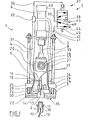
- a holding and scanning device 1 for an electrical connector 2 which consists essentially of a base plate 3 and a spaced therefrom by spacer bars 4 support plate 5, with a double-acting pneumatic piston 6 with a on the support plate corresponding pneumatic control device 7 is attached, the piston rod 8 of the pneumatic piston 6 points in the direction of the base plate 3 and is connected to a spring clip 9.
- the connector 2 shown consists of a plastic housing 10 with a circumferential collar 11, in which a metal plug contained h ggse 12 having an ailing cable. 13
- a recess 14 is made in the base plate 3, the shape of which corresponds to the front part of the connector housing 10 and into which the connector 2 is inserted for the cable test.
- a spring pin 16 is held in a block 15 screwed to the base plate 3, the lower tip 17 of which protrudes into the recess 14 and can be pushed back into an upper, thin tube 18 against the force of a spring (not shown).
- An electrical cable 19 is soldered to the spring pin 16 and is connected to a measuring computer for the electrical test or for testing many cables in a cable harness for a motor vehicle with a measuring computer.
- the spring clip 9 is essentially U-shaped, with two legs 20, 21 pointing in the direction of the base plate 3, which are bent conically outwards towards their free end and bend inwards in the end region and with their ends beveled towards the tips 22 end immediately at the recess 14.
- the conical areas 23 lie against guide blocks 24, 25 with a corresponding conical bevel.
- the spacer rods 4 are screwed into the base plate 3 with threads 26. These threads 26 are extended upwards and also carry the guide blocks 24, 25, d. H. by turning the guide blocks 24, 25, their height can be adjusted and adjusted along the threads 26. It can be seen that.
- the tips 22 of the spring legs 20, 21 are closer or further apart.
- the hose line 39 ends in a T-piece 32, of which a second hose line 33 is also guided to the base plate 3.
- a second, manually operated control valve 34 is attached there.
- This control valve 34 normally blocks the hose line 33, but opens it when the push button 35 is actuated, so that the control compressed air can escape.
- the detailed design of the second control valve 34 can be seen in FIG. 3.
- a further hose line 36 leads from the T-piece 32 to a third control valve 37 (the lines from and to this control valve 37 are shown in lines for the sake of clarity and the control valve 37 itself is only shown schematically; however, the control valve 37 is also attached to the support plate 5 directly next to the pneumatic piston-cylinder unit 6). If no pressure is built up in line 36, ie one of control valves 29 or 34 is open, control valve 37 has the switching state shown. Compressed air passes from the compressed air connection P via the switching path 38 and a line 39 to the upper connection 40 of the pneumatic cylinder 6, as a result of which the piston contained therein is pushed downward.
- a line 42 leads from a lower connection 41 of the cylinder 6 to the control valve 37 and via the switching path 43 contained therein to the ventilation opening 44.
- the push button 35 is actuated, as a result of which the control valve 34 opens and the pressure from the line 36 is reduced.
- the control valve 37 reverses, so that the piston rod is moved back down to the drawn starting position.
- the plug 2 which is held in its retracted state by the tips 22, is automatically ejected with an impact to the outside.
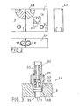
- FIG. 2 shows a front view of two adjacent base plates 3 in a desk (not shown).
- the drawing corresponds to the original size with a side length of the square base plate 3 of 5 cm.
- the front base plate area is kept as small as possible, since when testing wiring harnesses these are already tied together and the free ends have only a limited length, so that the connectors attached to them cannot be guided as far apart from one another as individual base plates 3 .
- the entire holding and scanning device 1 can thus be seen under the requirement of miniaturization.
- a spring clip 9 was also used, which encompasses the central scanning spring pin, so that no larger arrangements to the side of the scanning pin are required.
- a series of scanning spring pins 16 are then attached to the base plate 3, which have contact with a respectively assigned plug-in shoe when the plug is inserted.
- the spring clip 9 is also the same for larger plugs, only the spring legs 20, 21 are further apart.
- the spring clip 9 could not be formed from a continuous spring wire, but instead could have individual resilient legs, for example. It is only essential that conical articulation surfaces are present which, when the spring clip 9 moves upward, exert a gripping and pulling movement on an inserted plug. This gripping and pulling movement is to be carried out by a limit switch, in the exemplary embodiment shown by the scanning plate 30, are triggered so that the final position of the connector is independent of a reliable connector insertion by an operator.
- the control and movement of the spring clip 9 is carried out pneumatically in the exemplary embodiment shown.
- a pneumatic control has proven itself in practice due to its susceptibility to faults. It was also possible to build it very compactly.
- An additional advantage is that the gripping and pulling force can be adjusted by the pre-pressure in the pressure supply line.
- the holding and scanning device according to the invention can also be constructed using equivalent electrical means.
- the actuating rod 8 would then be connected, for example, to the moving coil of an electromagnet, which could be controlled by an electrical micro-limit switch in the recess 14.
- the plug could also be ejected after the measurement using a switch or button on the front of the base plate 3.
- connecting elements 48 are provided which are pressed into corresponding recesses provided on the narrow sides. These connecting elements 48 are made of plastic material and are curved approximately circularly on both sides. This results in an undercut that holds the base plates 3 together.
- the size of the connecting elements is selected so that they have to be pressed firmly into the corresponding recesses, are stuck there and do not protrude beyond the base plates 3.
- a threaded bore 49 is provided in the middle of the connecting elements. To solve is here only screwed in a screw, whereby the connecting element 48 is pressed out of the recesses.
- commercially available devices such as spring clips, etc. are also possible for fastening the individual holding and scanning devices.
- Fig. 3 the control valve 34 is shown in section and enlarged.
- the base plate 3 In the base plate 3 there is a hole which is narrower towards the front. The transition from the further opening to the narrower opening is the valve seat for a rubber circular cord ring 50. This is seated on a rotating part 51 which projects outwards and forms the push button 35 there.
- the rubber o-ring 50 is supported on a collar 52, which is loaded from the other side by a spring 53, and thus presses the rubber o-ring 50 onto the valve seat.
- the spring 53 is supported on a further rotating part 54 which is screwed into the base plate 3.
- the rotating part 54 contains a central bore and a socket 55, on which the hose 33 is inserted.
- a commercially available quick coupling could also be used as a connection to the hose 33.
- the control valve 29 is in its shown in two switch positions.
- a cuboid valve body is screwed to the base plate 3 with the aid of a screw 57 and secured against rotation by a centering pin 58.
- the lower side is set back in the area of the scanning plate 30, so that there is a gap 59 into which the scanning plate 30 can move freely.
- the valve body 56 contains a bore with a thread 60, at least in the upper part, into which the hose line 31 is screwed.
- the hose line 31 is made of conventional plastic material and is firmly connected to the valve body 56 by the screwing-in process. Depending on how far the hose line 31 is screwed in, the height of the lower edge 61 of the hose line 31 can be adjusted in height.
- this edge 61 serves as a valve seat.
- the scanning plate 30 is carried by a pin 62 which projects into a tubular valve insert 63.
- a spring 64 is arranged in the valve insert 63 and urges the pin 62 into its lower end position against a stop.
- the valve insert 63 is loosely inserted in the hose 31 from below, so that compressed air (arrows 65) can escape through a gap.
- the valve insert 63 has on its underside a thickening 66 with an upper, conical shoulder 67. The thickening is so large that it sits loosely with the formation of a gap in the bore in the valve body 56 and can be moved back and forth, but in diameter is larger than the inner diameter of the hose line 31.
- valve insert 63 and thus the pin 62 with the scanning plate 30 are only inserted from below into the valve body 56 before it is screwed to the base plate 3 and by falling out upwards due to the smaller hose diameter of the hose 31 and downwards through the attachment 68 secured in the base plate 3.
- FIG. 4 The position is shown in FIG. 4 when the valve 29 is open.
- the hose line 31 is screwed so far into the thread 60 that a sufficiently large gap remains between the thickening 66 and the edge 61 through which compressed air can flow.
- the scanning plate 30 and thus the valve insert 63 are either pulled down by the gravitational force or pushed by the compressed air in the direction of the open position.
- the control valve 37 is then moved downward in the position shown in FIG. 1 and the spring clip 9.
- the plug 2 is already inserted and the scanning plate 30 is thereby raised.
- the spring 64 initially remains in its extended position, as a result of which the thickening 66 or the conical shoulder 67 is guided upward to the lower edge 61 of the hose line 31 and abuts there.
- the hose line 31 is sealed. No rubber ring or the like is required here, since the elastic properties of the plastic hose line 31 are used for the tight connection.
- the seal is improved by the conical shape of the shoulder 67.
- the thickening 66 comes to rest on the edge 61 after a very short distance.
- the valve shown in FIGS. 4 and 5 is of extremely simple construction, since the hose line which is already present is also used as the sealing element. In addition, such The valve, as is also required in the present application, is extremely small and space-saving.
- a commercially available hose screw connection or quick coupling could be used, into which the valve insert 63 is inserted.
- This is a kind of pneumatic limit switch, which on the one hand does not need to be precisely adjusted due to the possibility of overpressing and on the other hand, as in the present case, can be installed directly in the travel range of a pneumatic control. A large number of applications in pneumatic controls are thus conceivable, separate from the present application example, in which miniaturization is important, so that the control valve is of independent importance.
- the object of the application shows a holding and scanning device that meets all practical requirements when testing cables and wire harnesses.
Landscapes
- Physics & Mathematics (AREA)
- General Physics & Mathematics (AREA)
- Details Of Connecting Devices For Male And Female Coupling (AREA)
- Measuring Leads Or Probes (AREA)
Applications Claiming Priority (2)
| Application Number | Priority Date | Filing Date | Title |
|---|---|---|---|
| DE3338770A DE3338770C1 (de) | 1983-10-26 | 1983-10-26 | Halte- und Abtastvorrichtung fuer einen elektrischen Stecker |
| DE3338770 | 1983-10-26 |
Publications (2)
| Publication Number | Publication Date |
|---|---|
| EP0141305A2 true EP0141305A2 (fr) | 1985-05-15 |
| EP0141305A3 EP0141305A3 (fr) | 1987-10-28 |
Family
ID=6212715
Family Applications (1)
| Application Number | Title | Priority Date | Filing Date |
|---|---|---|---|
| EP84112075A Ceased EP0141305A3 (fr) | 1983-10-26 | 1984-10-09 | Dispositif pour tenir et tâter un connecteur électrique |
Country Status (2)
| Country | Link |
|---|---|
| EP (1) | EP0141305A3 (fr) |
| DE (1) | DE3338770C1 (fr) |
Cited By (11)
| Publication number | Priority date | Publication date | Assignee | Title |
|---|---|---|---|---|
| FR2690250A1 (fr) * | 1992-04-15 | 1993-10-22 | Hernandez Jose | Dispositif de contrôle d'un boîtier de connexion installé à l'extrémité d'un faisceau de câbles électriques. |
| DE4241863C1 (de) * | 1992-12-11 | 1993-11-18 | Wee Electrotest Engineering Gm | Stecker-Kontaktiermodul für Geräte zum Prüfen von mit Steckern versehenen Kabelbäumen, z. B. für die Kraftfahrzeugelektrik |
| EP0565080A3 (en) * | 1992-04-07 | 1994-09-21 | Yazaki Corp | Inspection device for inspecting continuity of terminal in a connector |
| FR2717584A1 (fr) * | 1994-03-18 | 1995-09-22 | Sm Contact | Dispositif permettant de tester un ou plusieurs câbles électriques munis de connecteurs. |
| FR2736724A1 (fr) * | 1995-07-12 | 1997-01-17 | Etude Et Realisation De Comple | Procede et dispositif de controle de connecteurs electriques |
| WO1998016840A1 (fr) * | 1996-10-11 | 1998-04-23 | Jackmark Engineering Limited | Sonde de verification |
| ES2117540A1 (es) * | 1995-05-16 | 1998-08-01 | Mecanismos Aux Ind | Elemento contrapieza perfeccionado. |
| WO1998043317A1 (fr) * | 1997-03-26 | 1998-10-01 | Kirk Acoustics A/S | Dispositif de contact et outil servant a le manipuler |
| FR2803389A1 (fr) * | 2000-01-04 | 2001-07-06 | Serge Besnard | Prise de test electrique, appareillage et systeme mettant en oeuvre une telle prise |
| CN107994357A (zh) * | 2017-12-19 | 2018-05-04 | 上海晗普新材料科技有限公司 | 一种热缩焊锡终端连接器 |
| EP2768084B1 (fr) * | 2013-02-15 | 2019-09-04 | Gerd Thiede | Fermeture à cliquet pour fiche de test |
Families Citing this family (2)
| Publication number | Priority date | Publication date | Assignee | Title |
|---|---|---|---|---|
| DE3701621A1 (de) * | 1987-01-21 | 1988-08-04 | Helmuth Dipl Ing Kahl | Einrichtung zum pruefen eines oder mehrerer mit einem stecker versehener kabel |
| DE102005017241B3 (de) * | 2005-04-14 | 2006-07-13 | adaptronic Prüftechnik GmbH | Prüfvorrichtung für elektrische Verbindungselemente |
Family Cites Families (3)
| Publication number | Priority date | Publication date | Assignee | Title |
|---|---|---|---|---|
| FR1274626A (fr) * | 1960-09-15 | 1961-10-27 | Sncf | Prise de courant pour appareils d'éclairage situés à grande hauteur |
| DE3004428C2 (de) * | 1980-02-07 | 1983-01-05 | Klaus 7000 Stuttgart Rapp | Kontaktvorrichtung zur selbsttätigen vorübergehenden Verbindung von Litzen oder Drähten mit einer Prüfeinrichtung |
| DE3238949C2 (de) * | 1982-10-21 | 1985-03-14 | Hans-Jürgen 6477 Limeshain Wagner | Einrichtung zum Prüfen von mit Steckern versehenen Leitungen |
-
1983
- 1983-10-26 DE DE3338770A patent/DE3338770C1/de not_active Expired
-
1984
- 1984-10-09 EP EP84112075A patent/EP0141305A3/fr not_active Ceased
Cited By (13)
| Publication number | Priority date | Publication date | Assignee | Title |
|---|---|---|---|---|
| EP0565080A3 (en) * | 1992-04-07 | 1994-09-21 | Yazaki Corp | Inspection device for inspecting continuity of terminal in a connector |
| FR2690250A1 (fr) * | 1992-04-15 | 1993-10-22 | Hernandez Jose | Dispositif de contrôle d'un boîtier de connexion installé à l'extrémité d'un faisceau de câbles électriques. |
| DE4241863C1 (de) * | 1992-12-11 | 1993-11-18 | Wee Electrotest Engineering Gm | Stecker-Kontaktiermodul für Geräte zum Prüfen von mit Steckern versehenen Kabelbäumen, z. B. für die Kraftfahrzeugelektrik |
| FR2717584A1 (fr) * | 1994-03-18 | 1995-09-22 | Sm Contact | Dispositif permettant de tester un ou plusieurs câbles électriques munis de connecteurs. |
| ES2117540A1 (es) * | 1995-05-16 | 1998-08-01 | Mecanismos Aux Ind | Elemento contrapieza perfeccionado. |
| FR2736724A1 (fr) * | 1995-07-12 | 1997-01-17 | Etude Et Realisation De Comple | Procede et dispositif de controle de connecteurs electriques |
| WO1998016840A1 (fr) * | 1996-10-11 | 1998-04-23 | Jackmark Engineering Limited | Sonde de verification |
| WO1998043317A1 (fr) * | 1997-03-26 | 1998-10-01 | Kirk Acoustics A/S | Dispositif de contact et outil servant a le manipuler |
| US6239393B1 (en) | 1997-03-26 | 2001-05-29 | Kirk Acoustics A/S | Contact device and a tool for handling it |
| FR2803389A1 (fr) * | 2000-01-04 | 2001-07-06 | Serge Besnard | Prise de test electrique, appareillage et systeme mettant en oeuvre une telle prise |
| EP2768084B1 (fr) * | 2013-02-15 | 2019-09-04 | Gerd Thiede | Fermeture à cliquet pour fiche de test |
| CN107994357A (zh) * | 2017-12-19 | 2018-05-04 | 上海晗普新材料科技有限公司 | 一种热缩焊锡终端连接器 |
| CN107994357B (zh) * | 2017-12-19 | 2023-05-09 | 苏州晗普新材料科技有限公司 | 一种热缩焊锡终端连接器 |
Also Published As
| Publication number | Publication date |
|---|---|
| DE3338770C1 (de) | 1985-05-15 |
| EP0141305A3 (fr) | 1987-10-28 |
Similar Documents
| Publication | Publication Date | Title |
|---|---|---|
| DE3239708C2 (fr) | ||
| DE60209094T2 (de) | Vorrichtung und Verfahren zum Anschliessen von Kabeln | |
| DE3338770C1 (de) | Halte- und Abtastvorrichtung fuer einen elektrischen Stecker | |
| DE69323227T2 (de) | Inspektionseinrichtung zum Kontrollieren der Kontinuität der Klemmen eines Verbinders | |
| DE69619467T2 (de) | Elektrischer Verbinder mit Kontaktlagesicherungsvorrichtung welche das vollständige Einsetzen der Kontakte erleichtert | |
| DE3308178C1 (de) | Leitungsklemmvorrichtung | |
| DE602004008457T2 (de) | Kontakthaltereinheit für eine elektrische verbindungssteckbuchse oder einen elektrischen steckverbinder | |
| EP3073577B1 (fr) | Fiche male, connecteur a fiches et procede de fabrication d'une fiche male | |
| DE102021120916A1 (de) | Elektrische Verbinderstruktur und elektrische Verbinderbaugruppe | |
| DE2046430C3 (de) | Prüfanordnung zum Anschalten von zu prüfenden Ausrüstungen, wie Relaisschutz- und Automatikausrüstungen, an Prüfapparate | |
| DE69400472T2 (de) | Vorrichtung und Maschine zum Einfügen von Verbindungselementen in Verbindern | |
| DE60313511T2 (de) | Koaxialkontakt | |
| EP0335093A2 (fr) | Borne de contact électrique sans vis | |
| DE3238949C2 (de) | Einrichtung zum Prüfen von mit Steckern versehenen Leitungen | |
| DE102019106352B4 (de) | Leiteranschlussklemme mit einem Betätigungselement umfassend ein Mitnehmerelement | |
| EP1463160B1 (fr) | Connecteur à fiche ayant un élément coulissant pour la connexion à une prise | |
| EP2779328A1 (fr) | Procédé et dispositif de fabrication d'un connecteur | |
| DE8713233U1 (de) | Vorrichtung zum Zusammenstellen und Prüfen von Kabelbäumen aus Einzelkabeln | |
| DE3815587A1 (de) | Vorrichtung zum aufsetzen und aufquetschen von anschlussstuecken auf elektrischen leitern | |
| DE19949386A1 (de) | Geräte-Anschlusskasten mit Schneidtechnik | |
| DE3300136A1 (de) | Einrichtung zur herstellung elektrischer kontaktverbindungen mit den kontakten einer steckvorrichtung, insbesondere pruefadapter zum anschluss von mit einer steckvorrichtung versehenen elektrischen bauteilen an eine pruefeinrichtung | |
| EP0512088B1 (fr) | Levier de commutateur de colonne de direction pour vehicules a moteur | |
| EP0141086B1 (fr) | Borne de raccordement pour installation basse tension, en particulier pour interrupteurs | |
| DE4121764A1 (de) | Vorrichtung zum verbinden einer kabelmess- und pruefeinrichtung mit an eine gekapselte schaltanlage angeschlossenen kabeln | |
| EP0617482A2 (fr) | Fiche de raccordement au secteur |
Legal Events
| Date | Code | Title | Description |
|---|---|---|---|
| PUAI | Public reference made under article 153(3) epc to a published international application that has entered the european phase |
Free format text: ORIGINAL CODE: 0009012 |
|
| AK | Designated contracting states |
Designated state(s): AT CH DE FR GB IT LI SE |
|
| PUAL | Search report despatched |
Free format text: ORIGINAL CODE: 0009013 |
|
| AK | Designated contracting states |
Kind code of ref document: A3 Designated state(s): AT CH DE FR GB IT LI SE |
|
| 17P | Request for examination filed |
Effective date: 19871126 |
|
| 17Q | First examination report despatched |
Effective date: 19891128 |
|
| STAA | Information on the status of an ep patent application or granted ep patent |
Free format text: STATUS: THE APPLICATION HAS BEEN REFUSED |
|
| 18R | Application refused |
Effective date: 19900526 |